Abstract
In the vascular niche, the extracellular matrix (ECM) provides a structural scaffold with a rich ligand landscape of essential matrix proteins that supports the organization and stabilization of endothelial cells (ECs) into functional blood vessels. Many of the physical interactions between ECs and macromolecular components of the ECM occur at both the micron and sub-micron scale. In addition, the elasticity of the ECM has been shown to be a critical factor in the progress of the angiogenic cascade. Here we sought to determine the effect of substrate topography and elasticity (stiffness) on EC behavior. Utilizing a unique SiO2 substrate with an array of micropillars, we first demonstrate that micropillars with heights >3 μm significantly decrease EC adhesion and spreading. Fibronectin (Fn) patterning onf 1 μm high micropillars enabled EC adhesion onto the micropillars and promoted alignment in a single-cell chain manner. We then developed a robust method to generate a soft micropillar substrate array made of polydimethylsiloxane (PDMS), similar to the SiO2 substrate. Finally, we examined the kinetics of EC adhesion and spreading on the soft PDMS substrates compared to the stiff SiO2 substrates. Cell culturing on the PDMS substrates demonstrated an enhanced EC elongation and alignment when compared to stiff SiO2 with similar topographical features. We conclude that the elongation and alignment of ECs is co-regulated by substrate topography and stiffness and can be harnessed to guide vascular organization.
Introduction
The extracellular matrix (ECM) is a complex and heterogenic structure, presenting a myriad of instructive biochemical cues throughout a rich topographical architecture to influence cell behavior, and play an integral role in the regulation of vascular morphogenesis.1 Although ECM is prevalent throughout the body, specific composition, function, and matrix elasticity2 of ECM components is entirely tissue dependent. A critical function of the vascular ECM is to provide a structural scaffold with a ligand landscape of essential matrix proteins that supports the organization and stabilization of endothelial cells (ECs) into functional blood vessels.3 Cellular interactions with the ECM, through both physical and biochemical signaling events, influence fundamental EC functions and regulate the process of angiogenesis.
Many of the physical interactions between ECs and macromolecular components of the ECM, including collagens and fibronectin, occur at the micron and sub-micron scale. As the most abundant ECM component, collagen monomers are within the nanoscale regime, approximately 300 nm in width and 1.5 nm in diameter.4,5 When forming self-assembled fibrillar structures, collagen molecules extend several micrometers in length and hundreds of nanometers in diameter.6 Soluble fibronectin (Fn) is secreted by cells with a diameter of 2 nm and lengths of 100 nm7 and assembles into a fibrillar network.8 The ECM provides these topographical guidance cues, which play important roles in regulating cell behavior.9-15 Cells interact with nanometer-sized ECM molecules,10,16 and adhesion to the ECM initiates the first step of angiogenesis, regulating EC migration and proliferation.17-19
Elasticity of the ECM is a critical factor in the angiogenic cascade. Substrate stiffness has been reported to be influential in regulating cell-cell adhesion20 and inducing morphological changes.2,21 Alterations in matrix mechanics and biochemical signaling affect the binding affinity of EC mechanotransducing integrins and ECM ligands,22 moderating cell adhesion kinetics to the matrix through the formation of focal adhesion complexes23 and rearrangement of the cytoskeleton.24 Extracellular matrix stiffness influences EC interactions with the matrix, modulating necessary aspects of vessel formation, including cell migration and matrix remodeling.25 Recently, matrices with a compliant elasticity have been reported to stimulate the self-assembly of ECs into network structures in vitro,26,27 while substrates with a higher elastic modulus, or a more stiff matrix, had decreased network formation.28,29
With advancements in micro- and nanotechnology, recent studies have fabricated micro- and nanoscale substrates, with topographical and elasticity components to analyze adhesion, proliferation, and migration properties of cells.30-32 Specifically, polydimethylsiloxane (PDMS) micropillars, channels, and ridges can be fabricated to more closely mimic physiologically-relevant mechanical properties, and be used to validate the critical involvement of environmental elasticity on cell functions,31-32 found to occur through micromechanical cell forces.31,33 These substrates have shown both enhanced EC alignment,14 elongation,34 and structure formation,32 and also weak EC alignment and migration.35 Sub-micron (<1 μm, but greater than 100 nm) scale substrates have been shown to increase EC adhesion,34,36-38 migration,14 and orientation.39 For example, Bettinger et al. demonstrated the response of endothelial progenitor cells (EPCs) on soft PDMS nanotopographical substrates.32 Their results demonstrate alignment, elongation, and enhanced migration on periodic nano grooves, and organized capillary-like structure formation. Contrasting studies have shown that nanometer-scaled surfaces result in weak alignment and adhesion of human artery ECs,35 but increased adhesion and proliferation of mouse ECs.40 A study of nano-structured substrates have elicited increased proliferation41 and motile phenotype expression in bovine ECs,42 and induced differentiation of mesenchymal stem cells to endothelial lineage.40 Furthermore, EC spreading and alignment is enhanced on topographies with 1 μm dimensions.30 However, in all cases there is inconclusive data demonstrating the exact dimensional and stiffness influence on endothelial cellular behavior. Therefore, the development of combinatorial arrays to determine the influence of topographical features on specific cellular functions has become an emergent field of research.43-45
Our previous work demonstrated that patterning Fn in specific dimensions and spacing on flat surfaces led to the ordered adhesion of human endothelial progenitor cells (EPCs) and unidirectional tube formation in 3D.46 Here, we determine the combinatorial effects of topography and elasticity (stiffness) cues on EC behavior. Utilizing a SiO2 substrate with arrays of micropillars, we first determined the topographical features that support adhesion of ECs. Utilizing Fn patterning, we further directed the EC attachment onto such topographical features. We then developed a robust method to generate soft micropillar substrates made of PDMS, with arrays of micropillars similar to the SiO2 substrate. Finally, we examined the kinetics of EC adhesion and spreading on the soft PDMS substrates compared to the stiff SiO2 substrates.
Experimental
Micropillar substrate fabrication
SiO2 micropillars
A 6-μm layer of low-temperature oxide was deposited on 200 mm standard Si wafers. After a sintering step at 455°C, standard I-line lithography was used to define the micropillar arrays. Micropillar arrays ranged from 1-5.6 μm in diameter, with the spacing between micropillars ranging from 0.6-15 μm. Next, a timed reactive ion etch was performed in order to create the micropillar height. Final micropillar heights were 1, 3, 6, or 8 μm. Wafers were then diced, and the remaining resist was removed by submerging substrates in a 3:1 (v/v) H2SO4:H2O2 solution for 15 min.
PDMS micropillars
Polydimethylsiloxane micropillar substrates were fabricated using an established replicamolding technique.33 First, a negative of the original SiO2 micropillar substrate was made. Polydimethylsiloxane prepolymer solution and curing agent was prepared in a 10:2 (w/w) ratio (Sylgard, Dow Corning) and poured over a Si master of the original micropillar structures composed of photoresist, and cured for 24 h at 25°C. Negative PDMS substrates were submerged in acetone, and subsequently peeled apart. To make the positive PDMS micropillar substrates, a 10:1 (w/w) ratio of PDMS prepolymer solution and curing agent was poured over the negative PDMS substrates, cured for 24 h at 25°C, and peeled in the presence of ethanol. Samples were stored in 100% ethanol until use.
Fn patterning on SiO2 and PDMS micropillar substrates
First, SiO2 substrates were cleaned using a solution of sulfuric acid (OM Group) and hydrogen peroxide (Honeywell) (3:1 v/v) for 15 minutes, rinsed in 100% ethanol and de-ionized water, and then dried with N2. Then, both SiO2 and PDMS substrates were subjected to oxygen ozone treatment (15 min for SiO2 substrates, 30 min for PDMS substrates) (Jelight, Irvine, CA). Following this surface treatment, substrates were immediately immersed in a 2% (v/v) solution of 11-(triethoxysilyl)undecanal (TESU, MW 332.56, ABCR, Karlsruhe, Germany) in 95% (v/v) ethanol with 200 μL acetic acid, and allowed to react for 5 min. Substrates were then rinsed with 100% ethanol, dried with N2, and heated in an oven for at least 15 min at 110°C. Thereafter, TESU-coated substrates were sterilized in 100% ethanol and introduced to a tissue culture hood. All subsequent steps were performed under sterile conditions. Polydimethylsiloxane microcontact printing stamps, with striped features of 40 μm widths, were rinsed with ethanol and dried with N2. A 50 μg/ml solution of Fn in PBS was pipetted on top of the stamp for 1 min. Excess Fn solution was removed, and the PDMS stamp was dried with N2 and immediately held in contact with the substrate for 1 min. After stamping, patterned substrates were submerged in cyanoborohydride (CNBH, Sigma) for 10 min, followed by ethanolamine (Sigma, 1 M in H2O, pH 8.5) for 10 min, and three rinses in PBS.
Cell culture
Expansion
Human endothelial colony forming cells (ECFCs, passages 1-10, Lonza, Walkersville, MD) were cultured in endothelial growth medium (EGM-2, Lonza) according to manufacturer’s instructions. Human umbilical vein endothelial cells (HUVECs, passages 1-6, Lonza) were maintained in endothelial growth medium (EGM, Lonza). Both cell types were cultured in a humidified incubator at 37°C in an atmosphere containing 5% CO2, with media renewal every other day. Cells were passaged every 3-4 days with 0.05% trypsin/0.1% ethylenediaminetetraacetic acid (EDTA, Invitrogen, Carlsbad, CA).
Culture on Fn patterned SiO2 and PDMS micropillar substrates
Human ECFCs and HUVECs were grown to confluence, washed with PBS, and digested using 0.05% trypsin/0.1% EDTA. Densities of 2.5-3 x 10⁴ cells were seeded onto each micropillar substrate, which was either entirely coated with Fn or patterned with Fn. Substrates were cultured in 24 well plates (Nunc), with 1 substrate occupying 1 well. Cells were imaged at the indicated time points using an inverted microscope (Bausch & Lomb). Experiments were stopped at either 24 or 48 h.
Viability and immunofluorescent staining
We performed live/dead staining using calcein and ethidium bromide (Invitrogen). Briefly, human ECFCs and HUVECs cultured on substrates were washed once with PBS, replaced with EGM growth media containing calcein and ethidium bromide dye solution (both at 2 μM), and incubated for 30 min at 37°C. Substrates were then washed twice with PBS and immediately imaged using fluorescent microscopy (Olympus BX60).
For immunofluorescence, human ECFCs and HUVECs cultured on micropillar substrates for 1-2 days were fixed with 3.7% formaldehyde (Fisher Chemical, Fairlawn, NJ) in PBS for 20 min and washed with PBS. Substrates were submerged for 1 h in 1% BSA to prevent non-specific binding, then incubated with mouse anti-vascular endothelial cadherin (VE-CAD, 1:200, BD Biosciences) or mouse anti-fibronectin (1:200, Sigma), and rinsed twice with PBS. Substrates were then incubated with goat anti-mouse 488 (1:100, Invitrogen) and/or FITC-conjugated phalloidin (1:40, Invitrogen). To visualize the nucleus, substrates were incubated for 5 min in propidium iodide (Invitrogen). Substrates were then mounted and imaged using fluorescence microscopy (Olympus BX60) or confocal microscopy (LSM 5 PASCAL, Carl Zeiss Inc).
SEM
Micropillar substrates were characterized using scanning electron microscopy (SEM, SU8000, Hitachi). After 24 h culture, HUVECs on Fn-patterned substrates were visualized using SEM to analyze cell extensions. Samples were fixed with formalin-free fixative for 20 min and washed with PBS. Samples were postfixed with 1 % osmium tetroxide for 20 min (Sigma, Allentown, PA), followed by dehydration in ethanol and a final submersion in hexamethyldisilazane (HMDS, Sigma) for 10 min. Samples were coated with gold using a sputter coater (Anatech Hummer 6.2 Sputter Coater) and visualized using a FEI Quanta 200 ESEM.
Graphs and statistics
Cell areas and perimeters were analyzed using ImageJ software (NIH) and were used to calculate circularity, as a measure of cell elongation, as in our previous publications,46 using the following formula: C=4πA/P2 where A is the projected area of the cell and P is the perimeter. Cell area was determined using Image J software. Graphs for viability, cell area, and circularity were plotted with ± standard deviation (SD). Unpaired two tailed T-tests and parametric two-way ANOVA tests were performed where appropriate (GraphPad Prism 4.02, GraphPad Software, San Diego, CA). Significance levels were determined between sample examined (as described in figure legends), and were set at: *p<0.05, **p<0.01, and ***p<0.001. All graphical data were reported.
Results and Discussion
SiO2 oxide substrates
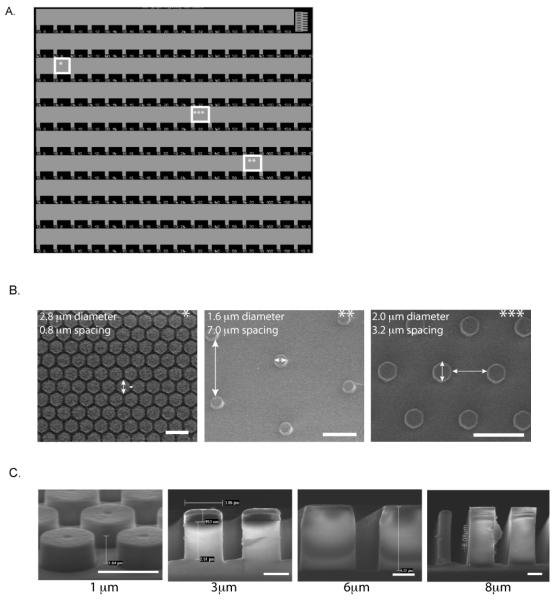
To examine the topographical and stiffness effect of sub-micron pillars on EC behavior, we patterned Fn, known to enhance EC growth and morphogenesis,47 on SiO2 substrates. These unique SiO2 substrates presented 150 distinct micropillar arrays ranging from 1-5.6 μm in diameter, with heights of 1, 3, 6, or 8 μm and spacing between the pillars ranging from 0.6-15 μm. This particular design, detailed in Fig. 1, allows the unique presentation of a vast number of topographical microenvironments on one substrate, enabling us to determine cellular responses to a wide range of feature dimensions. Each row of the SiO2 substrate presents a micropillar of a specific diameter. Subsequent arrays in that particular row have increasing lateral spacing between micropillars, providing many topographically distinct environments. Scanning electron micrographs of representative arrays (indicated by asterisks in Fig. 1A-C) demonstrate the extensive number of topographies available on the fabricated SiO2 substrates at distinct locations. Similar substrates with combinatorial arrays of varying surface topographies have been developed in order to optimize the design parameters of biomaterials45 for differentiation,44,48 and fibroblast responses.43
Figure 1. SiO2 micropillar substrates.
(A) Light microscope image of representative SiO2 micropillar substrate. SiO2 micropillar substrates were fabricated using I-line lithography followed by a timed reactive ion etch to create a unique substrate design presenting micropillar diameters ranging from 1-5.6 μm, with spacing between pillars ranging from 0.6-15 μm. (B) SEM images of various locations of the SiO2 micropillar substrate (indicated by stars), demonstrating wide array of design. (C) SEM images of SiO2 substrate of 1 μm, 3 μm, 6 μm, and 8 μm micropillar heights. Scale bar is 1 mm in (A), 5 μm in (B), and 2 μm in (C).
EC adhesion onto Fn-coated micropillar SiO2 substrates
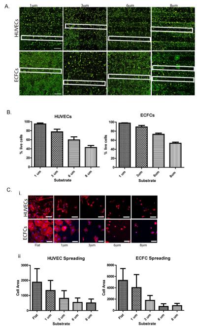
We determined initial viability, adhesion, and spreading of ECs on SiO2 micropillar substrates coated with Fn. Both human ECFCs and HUVECs were seeded onto these substrates and cultured in EGM. First, we investigated the influence of the overall micropillar height on cell viability after 24 h culture. We examined the adhesion of both ECFCs and HUVECs onto the Fn-coated micropillar substrates with different pillar heights of 1 μm, 3 μm, 6 μm, and 8 μm. A live/dead assay revealed that both HUVECs and ECFCs cultured on the Fn-coated micropillar substrates showed preferential adhesion to the flat regions of the substrate rather than to the 6 μm or 8 μm high micropillar arrays of the substrate (Fig. 2a). Endothelial colony forming cells showed a decreased percentage of live cells, 73% ± 6% and 53% ± 6% on 6 μm and 8 μm high micropillar arrays, respectively; whereas the percentage of live cells on 1 μm and 3 μm micropillar arrays after 24 h was much greater at 98% ± 2% and 89% ± 8%, respectively (Fig. 2b). Similar results were found with the HUVEC cell culture on Fn-coated SiO2 micropillar substrates. Although the entire substrate is coated with Fn, there is a clear effect of the topographical features, indicating that both ECs prefer adhesion to micropillars with heights <6 μm. This corresponds with previous studies that have highlighted the influence of topographical feature height on certain cellular functions, including proliferation, adhesion and differentiation.19,43-44,48 More specifically, topographical dimensions between 1 and 3 μm have demonstrated the highest biocompatibility with tissue attachment when implanted in vivo,49 which parallels our initial findings.
Figure 2. EC adhesion onto Fn-coated micropillared SiO2 substrates.
(A) HUVEC (upper panel) and ECFC (lower panel) adhesion onto Fn-coated micropillar SiO2 substrates with topographical feature heights ranging from 1-8 μm, cells stained with calcein (green-live staining). For clarification, some micropillar regions are outlined with a white box. (B) Quantification of percent of HUVEC (left) and ECFC (right) live cells on micropillar regions for each of the feature heights shows marked decreased percentage of live cells on substrates with topographical features with >3 μm heights. (C) HUVEC (upper panel) and ECFC (lower panel) expressing endothelial surface marker CD31 (red) have decreased cell spreading on substrates with topographical feature heights >1 μm as demonstrated by fluorescence microscope imaging (i) and cell spreading quantification (ii). Values shown are means ± SD. Scale bar is 1 mm in (A) and 100 μm in (C). Image analyses were performed on triplicate samples (n = 3).
Cell spreading of both cell types was also analyzed on Fn-coated micropillar substrates, and confirmed that both ECFCs and HUVECs prefer to adhere and spread on micropillar substrates with heights <6 μm (Fig. 2c). Furthermore, both HUVECs and ECFCs showed visibly decreased cell areas after 24 h culture on Fn-coated micropillar regions >1 μm. At topographical heights of 6 and 8 μm, the cells had distinctly altered cell morphologies, as previously shown.50 Therefore, we chose to continue our study focusing on SiO2 micropillar substrates of 1 μm height.
EC adhesion and alignment on Fn-patterned SiO2 subtrates
As shown in Fig. 2, the cell adhesion of both ECFCs and HUVECs was not exclusive to topographical regions and was observed outside the micropillar arrays (outlined by white boxes) on the flat regions of the substrate. To better control EC adhesion to specific regions, the 1 μm high micropillar substrates were patterned with Fn. Substrates were submerged in a TESU solution, forming a self-assembled monolayer with an aldehyde functionality. The PDMS stamp with striped features of 40 μm widths was then used to transfer Fn to the TESU-coated substrates, forming a double bond between the TESU aldehyde and amine groups of the Fn. The double bond was reduced with CNBH, and backfilled with ethanolamine to provide a cell resistive region (Supp. Fig. 1A).
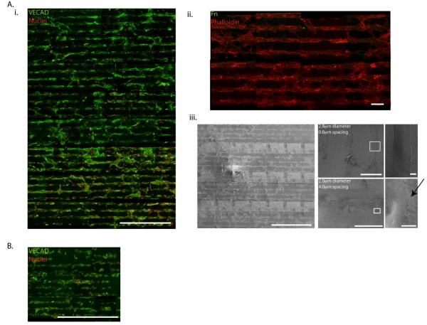
Both human ECFCs and HUVECs were cultured on the Fn-patterned 1 μm high micropillars with dimensions ranging from 1-5.6 μm in diameter, and spacing between pillars ranging from 0.6-15 μm. Human umbilical vein endothelial cells aligned on Fn patterns after 2 days in culture. Despite the large variance in topographical feature diameter and spacing, HUVECs aligned on Fn patterns on all micropillar arrays throughout the entire substrate, as shown by fluorescent microscopy images of VE-CAD and SEM images (Fig. 3). However, the density of adhesive protrusions differed based on topographical diameter and spacing. Images of large diameter micropillars with small spacing, such as micropillars with diameter of 2.8 μm and spacing of 0.8 μm, show few HUVEC extensions, as the small spacing between micropillars make the substrate appear more “flat.” Whereas on smaller diameter micropillars with larger spacing, such as 2 μm diameter micropillars with 4 μm spacing, more pronounced adhesive protrusions are observed, as indicated by arrows. Thus, while most micropillar arrays support cell attachment and alignment when patterned with Fn, there is a window of optimal micropillar array dimensions that facilitates cell extension.
Figure 3. EC adhesion and alignment on Fn-patterned SiO2 subtrates.
(A) ECs align on Fn patterns substrates after 2 days in culture. Despite large variances in topographical feature diameter and spacing, HUVECs align on Fn patterns throughout entire SiO2 substrate as shown by fluorescence microscope imaging of VECAD (green), propidium iodide (red) (i), and remain restricted to Fn patterns (Fn = green, phalloidin = red) (ii). SEM images show the density of HUVEC adhesive protrusions (indicated by an arrow) differs based on topographical diameter and spacing (iii). (B) ECFCs also align on Fn patterns, however adhesion and alignment is limited to topographical features with diameters ≤ 2.0 μm as shown by fluorescent micropscope imaging of VECAD (green), propidium iodide (red). Scale bar is 1 mm in (Ai), 100 μm in (Aii), and 1 mm, 100 μm, and 10 μm in (Aiii). Scale bar is 1 mm in (B).
Although we previously demonstrated the ability to guide the ordered adhesion of human EPCs on Fn-patterned flat substrates,46 the human ECFCs cultured on the Fn-patterned 1 μm high micropillars did not exhibit the same robust adhesive behavior as the HUVECs. Instead the ECFCs only aligned on patterned Fn micropillar arrays presenting topographical parameters of 1-2μm micropillar diameters, despite our ability to effectively pattern Fn on all arrays presented on the substrate (Supp. Fig. 1B). This may indicate that there is an optimal topographical cue size responsible for the organization and alignment of ECFCs, demonstrating a difference between the mature (HUVEC) and less mature (ECFC) endothelial phenotype.
Development of PDMS micropillar substrates
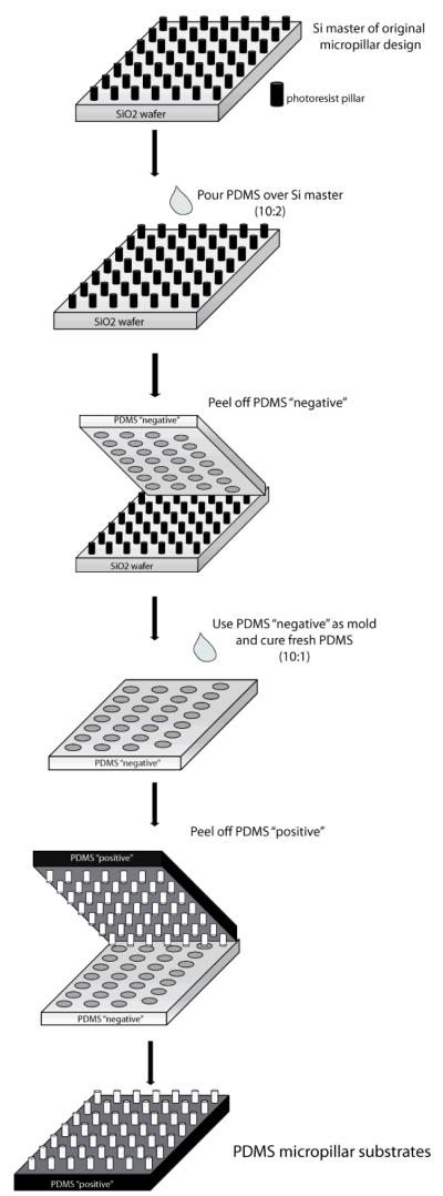
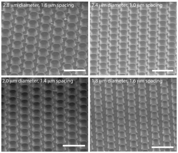
In order to analyze stiffness effects and mimic a more physiological, softer microenvironment, we created PDMS micropillar substrates similar to the SiO2 micropillar substrates. Using the SiO2 substrate as a master, we applied replica molding33 to first generate a PDMS “negative” of the SiO2 micropillar substrates. Then, we were able to create a “positive” PDMS substrate from our “negative” mold to create a PDMS substrate with a similar micropillar design (Fig. 4). In this way, we were able to generate substrates presenting “softer” topographical cues. Scanning electron microscopy confirmed that our process created PDMS topographical micropillars with heights of ~1-2 μm (Fig. 5). However, our technique was unsuccessful in replicating PDMS micropillars of every array on the substrate. Micropillar arrays that had an extremely small distance in between pillars were difficult to distinguish, and pillars with a relative high spacing distance compared to pillar diameter were not able to withstand the separation process of the “positive” PDMS substrate from the “negative”(Supp Fig 2).
Figure 4. Development of PDMS micropillar substrates.
Schematic describing the fabrication of PDMS “soft” micropillar substrates.
Figure 5. Characterization of PDMS micropillar substrates.
SEM images of fabricated PDMS micropillar substrates. Scale bar = 5 μm.
EC elongation of PDMS micropillar substrates
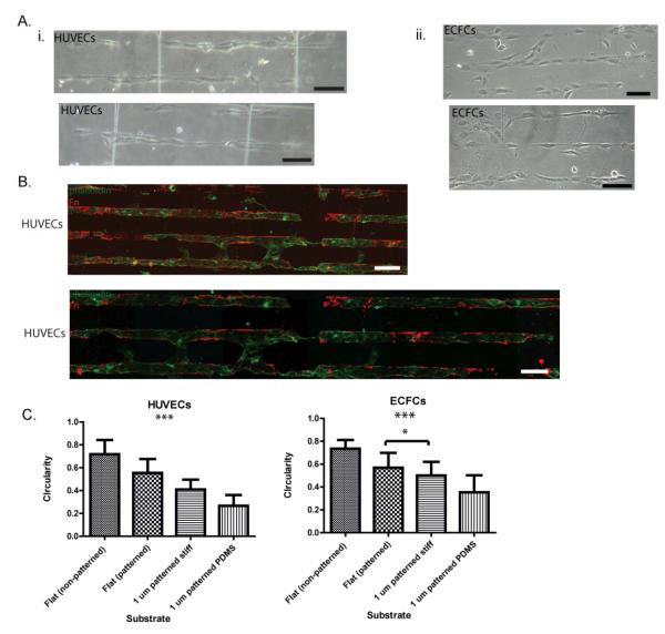
To achieve Fn-patterns on our soft PDMS micropillar substrates, we used the same protocol developed for the “stiff” SiO2 micropillar substrates, as PDMS is a crosslinked silicone and thus the same surface chemistry is applicable. Both HUVECs and ECFCs were seeded onto Fn-patterned PDMS micropillar substrates. Light microscope images demonstrate preferential adhesion of the HUVECs to the patterned PDMS micropillars, specifically in the micropillar array with dimensions: diameter 1.6-2.4 μm and spacing >5 μm. (Fig. 6). Human umbilical vein endothelial cells remain restricted to Fn patterns and demonstrate an elongated morphology after only 24 hours of culture on the soft PDMS substrates. Indeed, HUVEC and ECFC culture on Fn patterned PDMS micropillar substrates achieved much more elongated morphologies than when cultured on either Fn-patterned flat substrates or Fn-patterned stiff micropillared substrates. This suggests that soft substrates, when compared to stiff substrates with the same topographical features, direct aligned adhesion and enhanced elongation of ECs.
Figure 6. EC elongation of PDMS micropillar substrates.
(A) Light microscope images of HUVECs (i) and ECFCs(ii) demonstrate aligned and elongated morphologies after 24 h. (B) Flourescence microscope imaging of HUVECs stained with phalloidin (green) demonstrate successful patterning of PDMS micropillar substrates (Fn=red) and the preferential adhesion of HUVECs to Fn patterned regions. (C) Quantification of cell shape indicates significant HUVEC and ECFC elongation (a measure of circularity) on Fn-patterned SiO2 and PDMS micropillars compared to cells cultured on flat substrates. Significance levels were set at: *p < 0.05, **p < 0.01, and ***p < 0.001. Values shown are means ± SD.
Conclusions
Here we demonstrate the use of novel micropillar substrate arrays presenting a wide range of dimensions (1-5.6 μm in diameter and heights of 1, 3, 6, or 8 μm) and spacing (0.6-15 μm) to investigate the effects of substrate topography and stiffness on EC behavior. Results demonstrated that stiff SiO2 micropillar substrates with heights >3 μm significantly decreased EC adhesion and spreading. Fibronectin patterning of 1 μm high micropillar substrates enabled the restricted EC adhesion onto the micropillar arrays and promoted alignment in a single-cell chain manner. Micropillar substrates fabricated of PDMS were achieved using replica-molding to create soft substrates with a similar design to SiO2 substrates. Cell culture on PDMS substrates demonstrated an enhanced EC elongation and alignment when compared to stiff SiO2with similar topographical features. We conclude that the elongation and alignment of ECs is co-regulated by substrate topography and stiffness and can be harnessed to guide vascular organization.
Supplementary Material
Acknowledgements
We kindly thank Josine Loo and Nadine Collaert from imec for their help with SEM processing and imaging. L.E.D. is an IGERT trainee and a NSF Graduate Fellow. The research was partially supported through an International Research Experiences for Students grant from the NSF, NSF Grant 1054415 (for S.G), and by NIH grant U54CA143868.
References
- 1.van Obberghen-Schilling E, Tucker RP, Saupe F, Gasser I, Cseh B, Orend G. Fibronectin and tenascin-C: Accomplices in vascular morphogenesis during development and tumor growth. Int. J. of Dev. Biol. 2011;55(4-5):511–525. doi: 10.1387/ijdb.103243eo. [DOI] [PubMed] [Google Scholar]
- 2.Engler AJ, Sen S, Sweeney HL, Discher DE. Matrix Elasticity Directs Stem Cell Lineage Specification. Cell. 2006;126(4):677–689. doi: 10.1016/j.cell.2006.06.044. [DOI] [PubMed] [Google Scholar]
- 3.Wagenseil JE, Mecham RP. Vascular extracellular matrix and arterial mechanics. Physiol. Rev. 2009;89(3):957–989. doi: 10.1152/physrev.00041.2008. [DOI] [PMC free article] [PubMed] [Google Scholar]
- 4.Sun YL, Luo ZP, Fertala A, An KN. Direct quantification of the flexibility of type I collagen monomer. Biochem. Bioph. Res. Co. 2002;295(2):382–386. doi: 10.1016/s0006-291x(02)00685-x. [DOI] [PubMed] [Google Scholar]
- 5.Yadavalli VK, Svintradze DV, Pidaparti RM. Nanoscale measurements of the assembly of collagen to fibrils. Int. J. Biol. Macromol. 2010;46(4):458–464. doi: 10.1016/j.ijbiomac.2010.02.012. [DOI] [PubMed] [Google Scholar]
- 6.Bozec L, Van Der Heijden G, Horton M. Collagen fibrils: Nanoscale ropes. Biophys. J. 2007;92(1):70–75. doi: 10.1529/biophysj.106.085704. [DOI] [PMC free article] [PubMed] [Google Scholar]
- 7.Erickson HP, Carrell N, McDonagh J. Fibronectin molecule visualized in electron microscopy: a long, thin, flexible strand. J. Cell Biol. 1981;91(3):673–678. doi: 10.1083/jcb.91.3.673. [DOI] [PMC free article] [PubMed] [Google Scholar]
- 8.Schwarzbauer JE, Sechler JL. Fibronectin fibrillogenesis: a paradigm for extracellular matrix assembly. Curr. Opin. Cell Biol. 1999;11(5):622–627. doi: 10.1016/s0955-0674(99)00017-4. [DOI] [PubMed] [Google Scholar]
- 9.Flemming RG, Murphy CJ, Abrams GA, Goodman SL, Nealey PF. Effects of synthetic micro- and nano-structured surfaces on cell behavior. Biomaterials. 1999;20(6):573–588. doi: 10.1016/s0142-9612(98)00209-9. [DOI] [PubMed] [Google Scholar]
- 10.Curtis A, Wilkinson C. Topographical control of cells. Biomaterials. 1997;18(24):1573–1583. doi: 10.1016/s0142-9612(97)00144-0. [DOI] [PubMed] [Google Scholar]
- 11.Andrews K, Hunt J. Upregulation of matrix and adhesion molecules induced by controlled topography. J. Mater. Sci.- Mater. M. 2008;19(4):1601–1608. doi: 10.1007/s10856-008-3377-6. [DOI] [PubMed] [Google Scholar]
- 12.Gasiorowski JZ, Liliensiek SJ, Russell P, Stephan DA, Nealey PF, Murphy CJ. Alterations in gene expression of human vascular endothelial cells associated with nanotopographic cues. Biomaterials. 2010;31(34):8882–8888. doi: 10.1016/j.biomaterials.2010.08.026. [DOI] [PMC free article] [PubMed] [Google Scholar]
- 13.Kulangara K, Leong KW. Substrate topography shapes cell function. Soft Matter. 2009;5(21):4072–4076. [Google Scholar]
- 14.Liliensiek S, Wood J, Yong J, Auerbach R, Nealey P, Murphy C. Modulation of human vascular endothelial cell behaviors by nanotopographic cues. Biomaterials. 2010;31(20):5418–26. doi: 10.1016/j.biomaterials.2010.03.045. [DOI] [PMC free article] [PubMed] [Google Scholar]
- 15.Weiss P. Experiments on cell and axon orientation in vitro: the role of colloidal exudates in tissue organization. J. Exp. Zool. 1945;100:353–386. doi: 10.1002/jez.1401000305. [DOI] [PubMed] [Google Scholar]
- 16.Clark P, Connolly P, Curtis AS, Dow JA, Wilkinson CD. Cell guidance by ultrafine topography in vitro. J. Cell Sci. 1991;99(1):73–77. doi: 10.1242/jcs.99.1.73. [DOI] [PubMed] [Google Scholar]
- 17.Hynes RO. Cell–matrix adhesion in vascular development. JThromb Haemost. 2007;5:32–40. doi: 10.1111/j.1538-7836.2007.02569.x. [DOI] [PubMed] [Google Scholar]
- 18.Davis GE, Senger DR. Endothelial Extracellular Matrix. Circ Res. 2005;97(11):1093–1107. doi: 10.1161/01.RES.0000191547.64391.e3. [DOI] [PubMed] [Google Scholar]
- 19.Le Saux G, Magenau A, Bocking T, Gaus K, Gooding J. The relative importance of topography and RGD ligand density for endothelial cell adhesion. Plos One. 2011;6(7):e21869. doi: 10.1371/journal.pone.0021869. [DOI] [PMC free article] [PubMed] [Google Scholar]
- 20.Guo W, Frey M, Burnham N, Wang Y. Substrate rigidity regulates the formation and maintenance of tissues. Biophys J. 2006;90(6):2213–2220. doi: 10.1529/biophysj.105.070144. [DOI] [PMC free article] [PubMed] [Google Scholar]
- 21.McBeath R, Pirone DM, Nelson CM, Bhadriraju K, Chen CS. Cell shape, cytoskeletal tension, and RhoA regulate stem cell lineage commitment. Dev Cell. 2004;6(4):483–495. doi: 10.1016/s1534-5807(04)00075-9. [DOI] [PubMed] [Google Scholar]
- 22.Ingber D, Folkman J. Mechanochemical switching between growth and differentiation during fibroblast growth factor-stimulated angiogenesis in vitro: role of extracellular matrix. J Cell Biol. 1989;109:317–330. doi: 10.1083/jcb.109.1.317. [DOI] [PMC free article] [PubMed] [Google Scholar]
- 23.Discher DE, Janmey P, Wang Y. Tissue cells feel and respond to the stiffness of their substrate. Science. 2005;310:1139–1143. doi: 10.1126/science.1116995. [DOI] [PubMed] [Google Scholar]
- 24.Yeung T, Georges P, Flanagan L, Marg B, Ortiz M, Funaki M, Zahir N, Ming W, Weaver V, Janmey P. Effects of substrate stiffness on cell morphology, cytoskeletal structure and adhesion. Cell Motil Cytoskelet. 2005;60(1):24–34. doi: 10.1002/cm.20041. [DOI] [PubMed] [Google Scholar]
- 25.Salazar R, Bell S, Davis GE. Coordinate induction of the actin cytoskeletal regulatory proteins gelsolin, vasodilator-stimulated phosphoprotein, and profilin during capillary morphogenesis in vitro. Exp Cell Res. 1999;249(1):22–32. doi: 10.1006/excr.1999.4460. [DOI] [PubMed] [Google Scholar]
- 26.Califano JP, Reinhart-King CA. Exogenous and endogenous force regulation of endothelial cell behavior. J Biomech. 2010;43(1):79–86. doi: 10.1016/j.jbiomech.2009.09.012. [DOI] [PubMed] [Google Scholar]
- 27.Hanjaya-Putra D, Yee J, Ceci D, Truitt R, Yee D, Gerecht S. Vascular endothelial growth factor and substrate mechanics regulate in vitro tubulogenesis of endothelial progenitor cells. J Cell Mol Med. 2010;14(10):2436–2447. doi: 10.1111/j.1582-4934.2009.00981.x. [DOI] [PMC free article] [PubMed] [Google Scholar]
- 28.Sieminski A, Hebbel R, Gooch K. The relative magnitudes of endothelial force generation and matrix stiffness modulate capillary morphogensis in vitro. Exp Cell Res. 2004;297:574–584. doi: 10.1016/j.yexcr.2004.03.035. [DOI] [PubMed] [Google Scholar]
- 29.Critser PJ, Kreger ST, Voytik-Harbin SL, Yoder MC. Collagen matrix physical properties modulate endothelial colony forming cell-derived vessels in vivo. Microvasc Res. 2010;80(1):23–30. doi: 10.1016/j.mvr.2010.03.001. [DOI] [PMC free article] [PubMed] [Google Scholar]
- 30.Franco D, Klingauf M, Bednarzik M, Cecchini M, Kurtcuoglu V, Gobrecht J, Poulikakos D, Ferrari A. Control of initial endothelial spreading by topographic activation of focal adhesion kinase. Soft Matter. 2011;7(16):7313–7324. [Google Scholar]
- 31.Ghibaudo M, Di Meglio J-M, Hersen P, Ladoux B. Mechanics of cell spreading within 3D-micropatterned environments. Lab Chip. 2011;11(5):805–812. doi: 10.1039/c0lc00221f. [DOI] [PubMed] [Google Scholar]
- 32.Bettinger CJ, Zhang Z, Gerecht S, Borenstein JT, Langer R. Enhancement of In Vitro Capillary Tube Formation by Substrate Nanotopography. Adv Mater. 2008;20(1):99–103. doi: 10.1002/adma.200702487. [DOI] [PMC free article] [PubMed] [Google Scholar]
- 33.Tan JL, Tien J, Pirone DM, Gray DS, Bhadriraju K, Chen CS. Cells lying on a bed of microneedles: An approach to isolate mechanical force. P Natl Acad Sci USA. 2003;100(4):1484–1489. doi: 10.1073/pnas.0235407100. [DOI] [PMC free article] [PubMed] [Google Scholar]
- 34.Ranjan A, Webster T. Increased endothelial cell adhesion and elongation on micron-patterned nano-rough poly(dimethylsiloxane) films. Nanotechnology. 2009;20(30):305102. doi: 10.1088/0957-4484/20/30/305102. [DOI] [PubMed] [Google Scholar]
- 35.Biela SA, Su Y, Spatz JP, Kemkemer R. Different sensitivity of human endothelial cells, smooth muscle cells and fibroblasts to topography in the nano-micro range. Acta Biomater. 2009;5(7):2460–2466. doi: 10.1016/j.actbio.2009.04.003. [DOI] [PubMed] [Google Scholar]
- 36.Khang D, Lu J, Yao C, Haberstroh KM, Webster TJ. The role of nanometer and sub-micron surface features on vascular and bone cell adhesion on titanium. Biomaterials. 2008;29(8):970–983. doi: 10.1016/j.biomaterials.2007.11.009. [DOI] [PubMed] [Google Scholar]
- 37.Zorlutuna P, Rong Z, Vadgama P, Hasirci V. Influence of nanopatterns on endothelial cell adhesion: Enhanced cell retention under shear stress. Acta Biomater. 2009;5(7):2451–2459. doi: 10.1016/j.actbio.2009.03.027. [DOI] [PubMed] [Google Scholar]
- 38.Hwang SY, Kwon KW, Jang KJ, Park MC, Lee JS, Suh KY. Adhesion assays of endothelial cells on nanopatterned surfaces within a microfluidic channel. Anal Chem. 2010;82(7):3016–3022. doi: 10.1021/ac100107z. [DOI] [PubMed] [Google Scholar]
- 39.Lu J, Rao MP, MacDonald NC, Khang D, Webster TJ. Improved endothelial cell adhesion and proliferation on patterned titanium surfaces with rationally designed, micrometer to nanometer features. Acta Biomater. 2008;4(1):192–201. doi: 10.1016/j.actbio.2007.07.008. [DOI] [PubMed] [Google Scholar]
- 40.Park J, Bauer S, Schmuki P, Von Der Mark K. Narrow window in nanoscale dependent activation of endothelial cell growth and differentiation on TiO2 nanotube surfaces. Nano Lett. 2009;9(9):3157–3164. doi: 10.1021/nl9013502. [DOI] [PubMed] [Google Scholar]
- 41.Peng L, Eltgroth ML, LaTempa TJ, Grimes CA, Desai TA. The effect of TiO2 nanotubes on endothelial function and smooth muscle proliferation. Biomaterials. 2009;30(7):1268–1272. doi: 10.1016/j.biomaterials.2008.11.012. [DOI] [PubMed] [Google Scholar]
- 42.Brammer KS, Oh S, Gallagher JO, Jin S. Enhanced cellular mobility guided by TiO2 nanotube surfaces. Nano Lett. 2008;8(3):786–793. doi: 10.1021/nl072572o. [DOI] [PubMed] [Google Scholar]
- 43.Kolind K, Dolatshahi-Pirouz A, Lovmand J, Pedersen FS, Foss M, Besenbacher F. A combinatorial screening of human fibroblast responses on micro-structured surfaces. Biomaterials. 2010;31(35):9182–9191. doi: 10.1016/j.biomaterials.2010.08.048. [DOI] [PubMed] [Google Scholar]
- 44.Lovmand J, Justesen J, Foss M, Lauridsen RH, Lovmand M, Modin C, Besenbacher F, Pedersen FS, Duch M. The use of combinatorial topographical libraries for the screening of enhanced osteogenic expression and mineralization. Biomaterials. 2009;30(11):2015–2022. doi: 10.1016/j.biomaterials.2008.12.081. [DOI] [PubMed] [Google Scholar]
- 45.Simon CG, Jr, Sheng LG. Combinatorial and high-throughput screening of biomaterials. Adv Mater. 2011;23(3):369–387. doi: 10.1002/adma.201001763. [DOI] [PubMed] [Google Scholar]
- 46.Dickinson LE, Moura ME, Gerecht S. Guiding endothelial progenitor cell tube formation using patterned fibronectin surfaces. Soft Matter. 2010;6(20):5109–5119. [Google Scholar]
- 47.George EL, Baldwin HS, Hynes RO. Fibronectins are essential for heart and blood vessel morphogenesis but are dispensable for initial specification of precursor cells. Blood. 1997;90(8):3073–3081. [PubMed] [Google Scholar]
- 48.Markert LD, Lovmand J, Foss M, Lauridsen RH, Lovmand M, Füchtbauer EM, Füchtbauer A, Wertz K, Besenbacher F, Pedersen FS. Identification of distinct topographical surface microstructures favoring either undifferentiated expansion or differentiation of murine embryonic stem cells. Stem Cells Dev. 2009;18(9):1331–1342. doi: 10.1089/scd.2009.0114. others. [DOI] [PubMed] [Google Scholar]
- 49.von Recum AF, van Kooten TG. The influence of micro-topography on cellular response and the implications for silicone implants. J Biomater Sci-Polym Ed. 1995;7(2):181–198. doi: 10.1163/156856295x00698. [DOI] [PubMed] [Google Scholar]
- 50.Su WT, Liao YF, Lin CY, Li LT. Micropillar substrate influences the cellular attachment and laminin expression. J Biomed Mater Res A. 2010;93(4):1463–1469. doi: 10.1002/jbm.a.32643. [DOI] [PubMed] [Google Scholar]
Associated Data
This section collects any data citations, data availability statements, or supplementary materials included in this article.


