Abstract
Purpose: Gantry sag is one of the well-known sources of mechanical imperfections that compromise the spatial accuracy of radiation dose delivery. The objectives of this study were to quantify the gantry sag on multiple linear accelerators (linacs), to investigate a multileaf collimator (MLC)-based strategy to compensate for gantry sag, and to verify the gantry sag and its compensation with film measurements.
Methods: The authors used the Winston–Lutz method to measure gantry sag on three Varian linacs. A ball bearing phantom was imaged with megavolt radiation fields at 10° gantry angle intervals. The images recorded with an electronic portal imaging device were analyzed to derive the radiation isocenter and the gantry sag, that is, the superior–inferior wobble of the radiation field center, as a function of the gantry angle. The authors then attempted to compensate for the gantry sag by applying a gantry angle-specific correction to the MLC leaf positions. The gantry sag and its compensation were independently verified using film measurements.
Results: Gantry sag was reproducible over a six-month measurement period. The maximum gantry sag was found to vary from 0.7 to 1.0 mm, depending on the linac and the collimator angle. The radiation field center moved inferiorly (i.e., away from the gantry) when the gantry was rotated from 0° to 180°. After the MLC leaf position compensation was applied at 90° collimator angle, the maximum gantry sag was reduced to <0.2 mm. The film measurements at gantry angles of 0° and 180° verified the inferior shift of the radiation fields and the effectiveness of MLC compensation.
Conclusions: The results indicate that gantry sag on a linac can be quantitatively measured using a simple phantom and an electronic portal imaging device. Reduction of gantry sag is feasible by applying a gantry angle-specific correction to MLC leaf positions at 90° collimator angle.
Keywords: isocenter, wobble, gantry sag, Winston–Lutz
INTRODUCTION
Gantry sag is a well-known issue in radiation therapy that involves the use of linear accelerator (linac) gantry rotation to deliver radiation to the patient.1, 2, 3, 4, 5 The gravity of several tons of radiation-generating and shielding materials inside the gantry causes the gantry rotation to deviate from the ideal trajectory, which is a perfect circle about the rotation axis. This nonideal gantry rotation, combined with other linac imperfections such as collimator misalignment, leads to the “wobble” of the radiation field centers (RFCs) around the radiation isocenter and thus compromises the spatial accuracy of radiation treatments. The RFC wobble is especially detrimental in linac-based stereotactic radiosurgery, where high level of spatial accuracy is required. In addition, nonideal gantry rotation has a similar adverse effect on gantry-mounted accessories, including the electronic portal imaging device (EPID), the kilovolt on-board imager, and the cone-beam computed tomography (CBCT) system.6, 7, 8, 9, 10 Geometric misalignment of these imaging systems, which can degrade the image quality11 and decrease the patient positioning accuracy,12 represents a challenge for image-based applications such as EPID-based dosimetry and quality assurance.13, 14
Many geometric calibration methods have been proposed to quantify and account for nonideal gantry rotation. Most of these methods have been designed for the CBCT systems on various platforms, such as C-arm,15 micro-CT,16, 17, 18 or linac gantry.19 Fahrig and Holdsworth15 used a metallic sphere to measure the nonideal gantry motion on a C-arm CBCT system. Jaffray et al.19 pioneered image-guided radiation therapy (IGRT) by developing a flat-panel CBCT system mounted on a linac gantry. They used a similar method to obtain a “flex map” that characterized the 2D shifts of the imaging system as a function of gantry angle.19 The flex map was then incorporated into CBCT image reconstruction to improve the image accuracy. As IGRT became widely implemented in radiation therapy clinics, numerous studies addressed the CBCT geometric calibration using x-ray projections of a ball bearing9 or more sophisticated phantoms.18, 20 These studies have the potential to improve the accuracy of CBCT; however, they were not designed to address the other adverse effect caused by nonideal gantry rotation: the wobble of the centers of megavolt radiation fields.
A commonly used method to measure the RFC wobble during gantry rotation is the star-shot, or spoke-shot, technique.1 In this technique, a radiographic film is placed perpendicular to the gantry rotation axis. Then, a slit radiation field is used to expose the film at several gantry angles to form a star pattern. This gantry star-shot method can be used to assess the wobble of RFCs in the plane of the film.1, 3 However, this approach does not measure the radial component (i.e., parallel to the gantry rotation axis) of the wobble, which is often referred to as gantry sag.21, 22 To overcome this problem, one can place the film parallel to the gantry rotation axis and perform two collimator star-shots, one at 0° gantry angle and the other at 180° gantry angle. The radial distance between the centers of the two collimator star patterns is determined as a measure of gantry sag.1, 23 Another method of measuring gantry sag with films is to irradiate a custom-designed block at gantry angles of 0° and 180°.22 These film-based approaches are limited in the number of gantry angles measured. Recently, Winkler et al.24 introduced an EPID-based method that uses the Winston–Lutz (W–L) test.25 They measured gantry sag at 40° gantry angle intervals, using a ball bearing fixed near the isocenter as a reference point.24 The advantage of the W–L method is its capability of measuring 3D RFC wobble during gantry rotation. In addition, the EPID enables easier and faster digital image processing than with film. Using the W–L method, Du and Gao measured the 3D RFC wobble at 10° gantry angle intervals.5 They demonstrated that the transverse component of the wobble can be reduced by eliminating a constant lateral misalignment of the mulitleaf collimator (MLC). The residual wobble is dominated by the radial component.
The objectives of the current work were (i) to quantify and compare the gantry sag, or the radial wobble of RFCs, on multiple linacs using the W–L method, (ii) to investigate an MLC-based strategy to compensate for the gantry sag, and (iii) to verify the gantry sag and its compensation with film measurements.
MATERIALS AND METHODS
Measurement of gantry sag
In this study, we used the definition of gantry sag as the radial (couch longitudinal) component of the RFC wobble during gantry rotation. We measured gantry sag on three Varian linacs (Varian Medical Systems, Palo Alto, CA), of types Clinac 21 EX (linac A), Clinac iX (linac B), and Trilogy (linac C). Each linac was equipped with a Varian Millennium-120 MLC and an EPID. The linacs had been in clinical use for 6.0 years (linac A), 3.5 years (linac B), and 6.0 years (linac C) years.
For each linac, a ball bearing phantom was placed near the isocenter using room lasers. The center of the ball bearing served as a reference point in this measurement. An MLC-shaped 10 (x) × 10 (y) cm2 square field was used to image the ball bearing at 37 gantry angles (180°, 170°, …, 0°, 350°, ..., 190°, 180.1°; Varian IEC 601-2-1 scale). We used the MLC, instead of the secondary jaws, to define the radiation fields because the MLC is more frequently used in the clinic as the radiation shaping device. The 37 EPID images were analyzed with an in-house MATLAB (MathWorks, Natick, MA) program to detect the radiation field edges and the circular edge of the ball bearing. On the basis of the radiation field edges, we localized the RFC (i.e., the central ray of the beam) at each gantry angle. The radiation isocenter was determined at the intersection of all central rays.12 Then, the RFC wobble was computed as the vector distance from the radiation isocenter to each central ray. The gantry sag was the radial component of the RFC wobble, which was a 1D function of gantry angle. The maximum gantry sag was calculated as the magnitude (peak-to-valley difference) of this function.
To study the effect of collimator angle on gantry sag, we performed the measurements described above at two collimator angles, 0° and 90°. At 0° collimator angle, the superior (toward gantry) and inferior (away from gantry) edges of the radiation fields were determined by the straight blade sides of MLC leaves. Therefore, the gantry sag measured at 0° collimator angle was independent of the accuracy of the leaf end positions. At 90° collimator angle, the gantry sag was affected by the leaf end position accuracy. At both collimator angles, the gantry sag was affected by nonideal gantry rotation.
To evaluate the reproducibility of gantry sag measurements, we performed three measurements on linac A within a six-month period.
MLC compensation for gantry sag
The RFC wobble is essentially small, undesired shifts of the RFC as the gantry or the collimator is rotated. These shifts, if systematic, may be remedied by offsetting the RFC by the opposite of the wobble.5 In the present study, we compensated for gantry sag by rotating the MLC to 90° and offsetting the MLC leaves. To do this, we fitted the measured gantry sag empirically using two sinusoidal functions:
| (2) |
where θ was the gantry angle, ranging from 0° to 360°, sag(θ) was the measured gantry sag at angle θ, and ai, bi, ci, di (i = 1, 2) were the fitting parameters. The purpose of fitting was to reduce random errors in the measured data. Then, we edited the leaf positions in the MLC file manually by subtracting the fitted gantry sag from the original leaf positions. Because the gantry sag varied with gantry angle, the adjustment of leaf positions was also gantry angle-specific. The precision with which we could edit the leaf positions was 0.1 mm. This precision was limited by our treatment record-and-verify software, MOSAIQ (Elekta-IMPAC Medical Systems, Sunnyvale, CA).
To test the feasibility of this strategy, we repeated the gantry sag measurements at 90° collimator angle with the MLC compensation. The corrected gantry sag was compared with the results without MLC compensation.
Verification with film measurements
The method described above was based on the concept of the W–L test. It involved the use of a ball bearing phantom, the EPID, and dedicated image analysis software. We used a more straightforward, film-based method to independently verify the gantry sag and its compensation. In this method, a 20 (x) × 10 (y) cm2 rectangular MLC field was created at 0° collimator angle. The X2 jaw was set to 0 cm so that only the left half of the MLC field was open for radiation. The other jaws (X1, Y1, and Y2) were set to 2 cm beyond the MLC field edges. This half-blocked beam was used to irradiate a radiographic film or a computed radiography (CR) imaging plate, which was placed on the treatment table at a source-to-film distance of 100 cm. We chose to use CR image plate (Agfa HealthCare, Greenville, SC) because of its availability and convenience in our clinic. In this study, we used the CR imaging plate like a film, i.e., without the cassette, for accurate measurement of the source-to-film distance. Hereinafter we refer to the CR image plate as “CR film”. The CR film was sandwiched between two 1-cm-thick buildup blocks. We delivered 5 MU of a 6 MV beam at 0° gantry angle. A square radiation field was produced on the left side of the CR film. Then, we delivered the same beam to this film at 180° gantry angle, producing a square radiation field on the right side of the CR film. The exposed CR film was digitized into a DICOM file. By visually examining the alignment of the superior or inferior borders between the left and right fields, we were able to determine qualitatively the direction of gantry sag as the gantry was moved from 0° to 180°. To further quantify the gantry sag on the CR film, we used the Hough transform method26 to detect the superior and inferior edges of the left and right fields. Then, the displacements between the detected edges were readily computed. A displacement was defined as positive if the superior or inferior border of the left field was superior to the same border of the right field.
This technique was also used at 90° collimator angle, with slight modifications. The MLC field was changed to 10 (x) × 20 (y) cm2, and the Y1 jaw was set to 0 cm. For each linac, three CR films were irradiated: (i) at 0° collimator angle, without MLC compensation; (ii) at 90° collimator angle, without MLC compensation; and (iii) at 90° collimator angle, with MLC compensation.
RESULTS
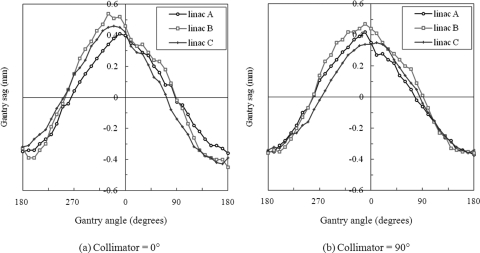
Figure 1 shows the gantry sag measured on the three Varian linacs. The sag was approximately sinusoidal in shape and had similar magnitudes for different linacs, indicating the consistency of the mechanical characteristics of machines from the same manufacturer. The RFC moved in the inferior direction as the gantry angle was changed from 0° to 180°. At 0° collimator angle, the maximum gantry sag was 0.77 mm (linac A), 0.99 mm (linac B), and 0.89 mm (linac C). At 90° collimator angle, the maximum gantry sag was 0.79 mm (linac A), 0.83 mm (linac B), and 0.71 mm (linac C). The uncertainty of MLC leaf positions at 90° collimator angle did not increase the gantry sag compared with that at 0° collimator angle; instead, the magnitudes and shapes of the gantry sag changed slightly, probably because of the altered weight distributions inside the gantry heads.
Figure 1.
Gantry sag at different gantry angles, measured on three linacs (A, B, and C). The collimator angle was fixed at either (a) 0° or (b) 90° during gantry rotation.
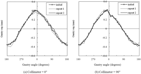
The reproducibility of gantry sag measurements is illustrated in Fig. 2. Variations among these measurements on the same linac (linac A) were clearly smaller than those among measurements on different linacs. At 0° collimator angle, the maximum gantry sag was 0.77 mm (initial), 0.77 mm (repeat 1), and 0.80 mm (repeat 2). At 90° collimator angle, the maximum gantry sag was 0.79 mm (initial), 0.78 mm (repeat 1), and 0.80 mm (repeat 2).
Figure 2.
Gantry sag at different gantry angles, measured three times on linac A: the first time (initial), 1 month later (repeat 1), and 6 months after the initial measurement (repeat 2). The collimator angle was fixed at either (a) 0° or (b) 90° during gantry rotation.
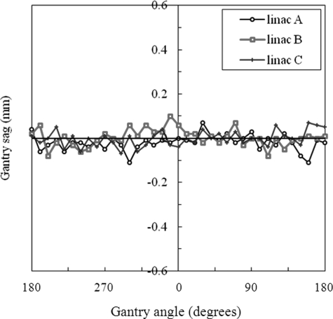
Figure 3 shows the measured gantry sag after the MLC-based compensation was applied. The collimator angle was 90° in these measurements. The maximum gantry sag was 0.18 mm (linac A), 0.18 mm (linac B), and 0.14 mm (linac C). Compared with Fig. 1b, the gantry sag reduced significantly at all gantry angles. The residual gantry sag was on the same order of magnitude as the precision (0.1 mm) with which we could edit the leaf positions (see Sec. 2B).
Figure 3.
Gantry sag at different gantry angles, measured on three linacs (A, B, and C) after a gantry angle-specific MLC leaf position compensation was applied. The collimator angle was 90°.
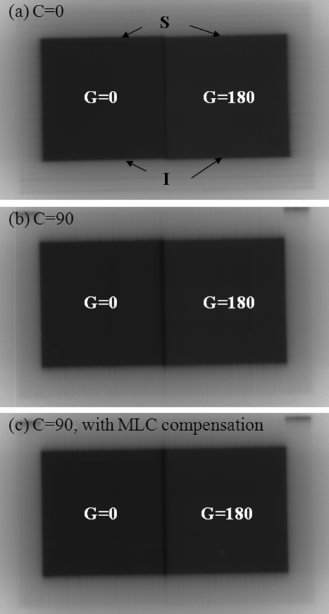
Figure 4 shows the three CR film measurements made on linac C. The gantry sag was verified on the films [Figs. 4a, 4b] regardless of whether the collimator was at 0° or 90°. By visual examination, the superior and inferior borders of the test radiation field shifted in the inferior direction when the gantry was moved from 0° to 180°. The misalignment of the superior or inferior field borders was indiscernible after the MLC leaf position compensation was applied [Fig. 4c]. Similar results were obtained on linacs A and B.
Figure 4.
Gantry sag caused small misalignments between the superior (S) or inferior (I) borders of a test radiation field when the gantry was moved from 0° (G = 0) to 180° (G = 180) on linac C. (a) Collimator angle 0°; (b) collimator angle 90°; (c) collimator angle 90° with MLC leaf position compensation.
Quantitative analysis of the field-border displacements on the CR films is given in Table TABLE I.. The displacements in Table TABLE I. agreed with the gantry sag measured using the W–L approach (Fig. 1). When MLC compensation was applied, the displacements were reduced to ≤0.16 mm. It is worth noting that the quality of the CR images was poorer than that of the EPID images because of physical imperfections from scratches and dust on the CR films. The uncertainty of localizing the superior or inferior field borders in the CR films was estimated to be ±0.2 mm.
TABLE I.
Displacement of the superior or inferior border of the test radiation field on CR films when the gantry was moved from 0° to 180°.
| Displacement (mm) | ||||||||
|---|---|---|---|---|---|---|---|---|
| Linac A | Linac B | Linac C | ||||||
| Film no. | Collimator angle (deg) | With MLC compensation | Superior | Inferior | Superior | Inferior | Superior | Inferior |
| 1 | 0 | No | 0.72 | 0.72 | 0.84 | 0.67 | 0.74 | 0.84 |
| 2 | 90 | No | 0.77 | 0.78 | 0.92 | 0.67 | 0.72 | 0.69 |
| 3 | 90 | Yes | 0.01 | 0.07 | 0.03 | 0.16 | 0.01 | 0.06 |
DISCUSSION
The gantry sag measured in this study is consistent with values reported in the literature. For example, Rosca et al.23 measured a 0.8 mm maximum gantry sag on a stereotactic Novalis linac. That measurement was done at four cardinal gantry angles. Winkler et al.24 measured gantry sag on a Varian linac at 40° gantry angle intervals and reported a 0.76 mm maximum gantry sag. In both those studies, the RFC was found to shift inferiorly as the gantry was moved from 0° to 180°. In this study, we quantified the gantry sag at 10° intervals on multiple Varian linacs. Each linac was found to have distinct gantry sag as a function of gantry angle (Fig. 1). With high resolution in gantry angle, Fig. 1a revealed that the gantry sag was not necessarily symmetric about 0° gantry angle. In addition, we studied the effect of collimator rotation on gantry sag and presented an MLC-based technique that fully compensated for the gantry sag.
The wobble of RFCs during gantry rotation is 3D in nature. In this study, we focused on one dimension: the longitudinal, or radial, dimension. The wobble in the transverse dimension is better known and is more frequently measured because of the widespread use of the gantry star-shot technique. The transverse wobble is affected by nonideal gantry rotation as well as collimator misalignment. Collimator misalignment has different effects on the transverse wobble and the radial wobble: transverse collimator misalignment increases the transverse wobble of RFCs but does not move the radiation isocenter,5 whereas longitudinal collimator misalignment shifts the RFCs at all gantry angles and the resulting radiation isocenter, thus leaving the radial wobble, or gantry sag, unchanged.
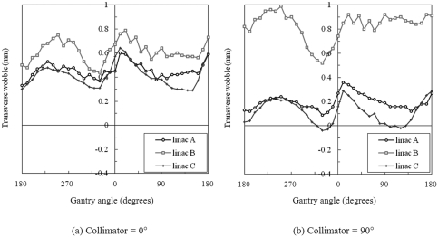
The collimator angle also affects the wobble of RFCs measured during gantry rotation. The gantry sag measurements are similar (Fig. 1) at collimator angles of 0° and 90°, indicating that gantry sag is dominated by gravity-induced nonideal gantry rotation, and not by leaf end position inaccuracy, which is present when the collimator is at 90°. The transverse wobble, however, is sensitive to the collimator angle. Figure 5 shows that the transverse wobble can increase (linac B) or decrease (linacs A and C) when the collimator is rotated from 0° to 90°. The change is probably caused by varied MLC misalignment at different collimator angles. As demonstrated in our previous work,5 the RFC may move along an approximately elliptical trace as the collimator is rotated. The collimator rotation-caused wobble would in effect change the amount of MLC transverse misalignment as seen in gantry rotation measurements, thus changing the transverse wobble (Fig. 5).
Figure 5.
Transverse RFC wobble at different gantry angles, measured on three linacs (A, B, and C). The collimator angle was fixed at either (a) 0° or (b) 90° during gantry rotation.
A limitation of the present study is that gantry sag is compensated only when the collimator is fixed at 90°. This strategy works best when there is no need for a specific collimator angle, for example, in treating a spherical target. Our previous study5 demonstrated that MLC compensation, if applied when the collimator is at 0°, can reduce the transverse wobble but not the gantry sag. Because the MLC leaves travel in one dimension, the idea of using MLC leaf position to compensate for RFC wobble is destined to work in that dimension only. To further reduce the wobble, this MLC-based strategy may be combined with a mechanical adjustment of the MLC position, that is, shifting the entire MLC system in the direction perpendicular to the leaf travel direction. For example, if the constant component of the transverse wobble in Fig. 5b were removed by mechanically shifting the MLC, the residual transverse wobble would be approximately 0.3 mm (linac A), 0.5 mm (linac B), and 0.4 mm (linac C) in range. With the radial wobble minimized by MLC leaf offsets, the 3D wobble during gantry rotation would be bounded by a sphere of diameter ≤0.5 mm. In comparison, without any compensation and at 0° collimator angle, the 3D wobble is bounded by a sphere of diameter 1.4 mm (linac A), 1.7 mm (linac B), and 1.4 mm (linac C).
In this study, the gantry sag and field misalignment were measured at the isocenter. The field misalignment may be different when measured at a distance away from the isocenter. Assuming a small target size (e.g., maximum distance of 5 cm from the isocenter) relative to the 100 cm source-to-axis distance, we expect that the field misalignment throughout the target would be similar to that at the isocenter.
It should also be noted that gantry sag is a relatively small uncertainty compared to other factors such as uncertainty in target delineation, patient setup error, and target movement. However, in stereotactic type of treatments where the other uncertainties are minimized, gantry sag may become significant and should be taken in account. For example, the margin expansion of the target should be designed to include the gantry sag of the linac.
CONCLUSIONS
We used the W–L method to measure gantry sag on three Varian linacs. The gantry sag varied from 0.7 to 1.0 mm, depending on the linac and the collimator angle. The RFC shifted inferiorly, or away from the gantry, as the gantry angle was changed from 0° to 180°. The gantry sag was systematic and thus could be accounted for. We demonstrated a strategy to compensate for the gantry sag by offsetting the MLC leaf positions at 90° collimator angle. In future work, simultaneous minimization of both the transverse and the radial components of RFC wobble may be possible by adjusting the MLC position in two dimensions.
ACKNOWLEDGMENTS
The authors thank Karen Muller of the Department of Scientific Publications for reviewing and scientific editing of this manuscript. This research is supported in part by the National Institutes of Health through MD Anderson’s Cancer Center Support Grant No. CA016672.
References
- Gonzalez A., Castro I., and Martinez J. A., “A procedure to determine the radiation isocenter size in a linear accelerator,” Med. Phys. 31, 1489–1493 (2004). 10.1118/1.1755491 [DOI] [PubMed]
- Skworcow P., Mills J. A., Haas O. C., and Burnham K. J., “A new approach to quantify the mechanical and radiation isocentres of radiotherapy treatment machine gantries,” Phys. Med. Biol. 52, 7109–7124 (2007). 10.1088/0031-9155/52/23/022 [DOI] [PubMed]
- Treuer H., Hoevels M., Luyken K., Gierich A., Kocher M., Muller R. P., and Sturm V., “On isocentre adjustment and quality control in linear accelerator based radiosurgery with circular collimators and room lasers,” Phys. Med. Biol. 45, 2331–2342 (2000). 10.1088/0031-9155/45/8/318 [DOI] [PubMed]
- Tsai J. S., “Analyses of multi-irradiation film for system alignments in stereotactic radiotherapy (SRT) and radiosurgery (SRS),” Phys. Med. Biol. 41, 1597–1620 (1996). 10.1088/0031-9155/41/9/003 [DOI] [PubMed]
- Du W. and Gao S., “Measuring the wobble of radiation field centers during gantry rotation and collimator movement on a linear accelerator,” Med. Phys. 38, 4575–4578 (2011). 10.1118/1.3609098 [DOI] [PubMed]
- Ali I. and Ahmad S., “Evaluation of the effects of sagging shifts on isocenter accuracy and image quality of cone-beam CT from kV on-board imagers,” J. Appl. Clin. Med. Phys. 10, 180–194 (2009). 10.1120/jacmp.v10i3.2930 [DOI] [PMC free article] [PubMed]
- Lehmann J., Perks J., Semon S., Harse R., and Purdy J. A., “Commissioning experience with cone-beam computed tomography for image-guided radiation therapy,” J. Appl. Clin. Med. Phys. 8, 21–36 (2007). 10.1120/jacmp.v8i3.2354 [DOI] [PMC free article] [PubMed]
- Rowshanfarzad P., Sabet M., O’Connor D. J., and Greer P. B., “Verification of the linac isocenter for stereotactic radiosurgery using cine-EPID imaging and arc delivery,” Med Phys 38, 3963–3970 (2011). 10.1118/1.3597836 [DOI] [PubMed]
- Sharpe M. B., Moseley D. J., Purdie T. G., Islam M., Siewerdsen J. H., and Jaffray D. A., “The stability of mechanical calibration for a kV cone beam computed tomography system integrated with linear accelerator,” Med. Phys. 33, 136–144 (2006). 10.1118/1.2143141 [DOI] [PubMed]
- von Smekal L., Kachelriess M., Stepina E., and Kalender W. A., “Geometric misalignment and calibration in cone-beam tomography,” Med. Phys. 31, 3242–3266 (2004). 10.1118/1.1803792 [DOI] [PubMed]
- Zhu S., Tian J., Yan G., Qin C., and Feng J., “Cone Beam Micro-CT System for Small Animal Imaging and Performance Evaluation,” Int. J. Biomed. Imaging 2009, 960573 (2009). 10.1155/2009/960573 [DOI] [PMC free article] [PubMed]
- Du W., Yang J., Luo D., and Martel M., “A simple method to quantify the coincidence between portal image graticules and radiation field centers or radiation isocenter,” Med. Phys. 37, 2256–2263 (2010). 10.1118/1.3397452 [DOI] [PubMed]
- Jorgensen M. K., Hoffmann L., Petersen J. B., Praestegaard L. H., Hansen R., and Muren L. P., “Tolerance levels of EPID-based quality control for volumetric modulated arc therapy,” Med. Phys. 38, 1425–1434 (2011). 10.1118/1.3552922 [DOI] [PubMed]
- Clarke M. F. and Budgell G. J., “Use of an amorphous silicon EPID for measuring MLC calibration at varying gantry angle,” Phys. Med. Biol. 53, 473–485 (2008). 10.1088/0031-9155/53/2/013 [DOI] [PubMed]
- Fahrig R. and Holdsworth D. W., “Three-dimensional computed tomographic reconstruction using a C-arm mounted XRII: Image-based correction of gantry motion nonidealities,” Med. Phys. 27, 30–38 (2000). 10.1118/1.598854 [DOI] [PubMed]
- Karolczak M., Schaller S., Engelke K., Lutz A., Taubenreuther U., Wiesent K., and Kalender W., “Implementation of a cone-beam reconstruction algorithm for the single-circle source orbit with embedded misalignment correction using homogeneous coordinates,” Med. Phys. 28, 2050–2069 (2001). 10.1118/1.1406514 [DOI] [PubMed]
- Yang K., Kwan A. L., Miller D. F., and Boone J. M., “A geometric calibration method for cone beam CT systems,” Med. Phys. 33, 1695–1706 (2006). 10.1118/1.2198187 [DOI] [PMC free article] [PubMed]
- Cho Y., Moseley D. J., Siewerdsen J. H., and Jaffray D. A., “Accurate technique for complete geometric calibration of cone-beam computed tomography systems,” Med. Phys. 32, 968–983 (2005). 10.1118/1.1869652 [DOI] [PubMed]
- Jaffray D. A., Siewerdsen J. H., Wong J. W., and Martinez A. A., “Flat-panel cone-beam computed tomography for image-guided radiation therapy,” Int. J. Radiat. Oncol., Biol., Phys. 53, 1337–1349 (2002). 10.1016/S0360-3016(02)02884-5 [DOI] [PubMed]
- Mennessier C., Clackdoyle R., and Noo F., “Direct determination of geometric alignment parameters for cone-beam scanners,” Phys. Med. Biol. 54, 1633–1660 (2009). 10.1088/0031-9155/54/6/016 [DOI] [PMC free article] [PubMed]
- LoSasso T., “IMRT delivery system QA,” in Intensity Modulated Radiation Therapy: The State of the Art. Medial Physics Monograph, Vol. 29, edited by Palta J. and Mackie T. R. (Medical Physics Publishing, Colorado Springs, 2003), pp. 561–591.
- Ford E. C. and Lutz W. R., “A block design for split-field tests of accelerator alignment,” Med. Phys. 31, 2331–2334 (2004). 10.1118/1.1773621 [DOI] [PubMed]
- Rosca F., Lorenz F., Hacker F. L., Chin L. M., Ramakrishna N., and Zygmanski P., “An MLC-based linac QA procedure for the characterization of radiation isocenter and room lasers’ position,” Med. Phys. 33, 1780–1787 (2006). 10.1118/1.2198171 [DOI] [PubMed]
- Winkler P., Bergmann H., Stuecklschweiger G., and Guss H., “Introducing a system for automated control of rotation axes, collimator and laser adjustment for a medical linear accelerator,” Phys. Med. Biol. 48, 1123–1132 (2003). 10.1088/0031-9155/48/9/303 [DOI] [PubMed]
- Lutz W., Winston K. R., and Maleki N., “A system for stereotactic radiosurgery with a linear accelerator,” Int. J. Radiat. Oncol., Biol., Phys. 14, 373–381 (1988) 10.1016/0360-3016(88)90446-4. [DOI] [PubMed]
- Du W. and Yang J., “A robust Hough transform algorithm for determining the radiation centers of circular and rectangular fields with subpixel accuracy,” Phys. Med. Biol. 54, 555–567 (2009). 10.1088/0031-9155/54/3/006 [DOI] [PubMed]


