Abstract
Aortic valve reconstruction using leaflet grafts made from autologous pericardium is an effective surgical treatment for some forms of aortic regurgitation. Despite favorable outcomes in the hands of skilled surgeons, the procedure is underutilized because of the difficulty of sizing grafts to effectively seal with the native leaflets. Difficulty is largely due to the complex geometry and function of the valve and the lower distensibility of the graft material relative to native leaflet tissue. We used a structural finite element model to explore how a pericardial leaflet graft of various sizes interacts with two native leaflets when the valve is closed and loaded. Native leaflets and pericardium are described by anisotropic, hyperelastic constitutive laws, and we model all three leaflets explicitly and resolve leaflet contact in order to simulate repair strategies that are asymmetrical with respect to valve geometry and leaflet properties. We ran simulations with pericardial leaflet grafts of various widths (increase of 0%, 7%, 14%, 21% and 27%) and heights (increase of 0%, 13%, 27% and 40%) relative to the native leaflets. Effectiveness of valve closure was quantified based on the overlap between coapting leaflets. Results showed that graft width and height must both be increased to achieve proper valve closure, and that a graft 21% wider and 27% higher than the native leaflet creates a seal similar to a valve with three normal leaflets. Experimental validation in excised porcine aortas (n=9) corroborates the results of simulations.
Keywords: finite element, aortic valve repair, membrane, surgical planning, leaflet graft, pericardium
1 Introduction
Aortic regurgitation (AR) is inadequate closure of the aortic valve resulting in reversal of blood flow into the left ventricle during diastole. Moderate to severe AR can overwork the heart, eventually requiring surgery. A common surgical treatment is to replace the valve with a mechanical valve, a bioprosthetic valve or the patient’s own pulmonary valve. However, each of these options has drawbacks, including lifelong anticoagulant therapy (mechanical valves), limited durability (bioprostheses), and dilatation of the aortic root (pulmonary autograft). Valve repair avoids these disadvantages of valve replacement (Bacha et al., 2008; Jonas, 2010). Valve repair for AR involves reconstruction of the native leaflets in order to create an effective seal during diastole. Furthermore, there should be overlap between adjacent closed leaflets during normal heart beats if the valve is to close completely during periods of high diastolic pressure (e.g., exercise). This overlap is termed “coaptation”.
A common repair strategy is to graft a leaflet created from the patient’s pericardium into the valve (Duran et al., 1995). However, valve leaflet tissue and treated pericardium exhibit different mechanical properties, and in our clinical experience it is difficult to determine the size of the graft that will form an effective seal with the remaining native leaflets when the valve is closed and loaded.
Computational models of the aortic valve have been used to study both normal (De Hart et al., 2003; Gnyaneshwar et al., 2002; Grande et al., 1998; Labrosse et al., 2010; Nicosia et al., 2003; Ranga et al., 2007) and diseased valves (Grande et al., 2000) and to evaluate bioprosthetic valves (Kim et al., 2007; Kim et al., 2008; Sun et al., 2005; Xiong et al., 2010). They have also been used to study valve repairs, including aortic root replacement with synthetic grafts (Grande-Allen et al., 2001) and replacement of all three valve leaflets with pericardium (Lim et al., 2004).
In this study, we use a structural finite element (FE) model of the aortic valve to explore the effect of pericardial leaflet graft size on the closed, loaded state of the repaired valve. Leaflets are described by nonlinear anisotropic constitutive laws, and we model all three leaflets and resolve intra- and inter-leaflet contact to simulate repairs that are asymmetrical with respect to valve geometry and leaflet properties. We explore surgical repair strategies by simulating the closed valve under end-diastolic pressure for different pericardial graft sizes.
2 Methods
2.1 Computational mesh of aortic valve
We create a computational mesh of the aortic valve by creating a mesh of a single leaflet, unstressed and lying in a plane, then assembling three single leaflet meshes into a full valve. Leaflet shape is taken from published studies (Labrosse et al., 2006; Swanson and Clark, 1974; Thubrikar, 1990). The curve describing the lower edge of an excised leaflet lying flat (i.e., the edge that attaches to the aortic root not including the commissures) takes the form y=sin2(x)/tan(γ) where γ is 34° (Swanson and Clark, 1974). Variables x and y are in normalized units relative to the diameter of the base of the aortic root, and leaflet width is 1.047 in normalized units. In absolute dimensions, we chose the diameter of the base of the aortic root to be 20 mm and commissure height to be 5 mm based on clinical observations (Fig. 1). An unstructured mesh of triangles is then created within the leaflet boundary (Persson & Strang, SIAM 2004) (Fig 1B).
Figure 1.
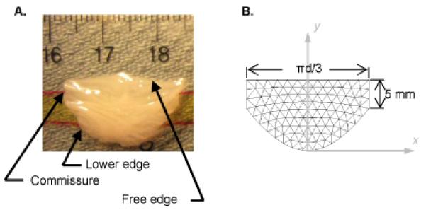
(A) Photograph of a fresh excised porcine aortic valve leaflet floating on a thin layer of phosphate-buffered saline. (B) Mesh of unstructured triangles in the shape of a single aortic valve leaflet. Leaflet width is expressed in terms of d, the diameter of the cylinder formed by joining three such leaflets at the commissures and “wrapping” them onto a cylinder.
The lower edges of the valve leaflets, along with the edges at the commissures, are attached to the aortic root, and the locus of points defining this attachment has been shown to lie on a cylinder (Labrosse et al., 2006; Swanson and Clark, 1974). Accordingly, we create a three-leaflet valve model by joining three planar leaflets at the commissures and wrapping them into a cylinder (Fig. 2A). We refer to the diameter of this cylinder as the diameter of the aortic root, ignoring the sinuses that bulge from the aortic root behind each leaflet. In this cylindrical mesh, we define the leaflets to be in their unstressed state, but the cylinder diameter does not necessarily correspond to the unstressed state of the aortic root, i.e., when trans-aortic pressure is zero. In fact, the sum of the lengths of the leaflet free edges is typically greater than the circumference of the unstressed aortic root (Fig. 3). Published data (Labrosse et al., 2010), corroborated by our images of pressurized porcine aortas, show the sum of the leaflet free edges to be approximately 15% greater than this circumference. Thus, we compute the diameter of the root at zero pressure as 20 mm divided by 1.15.
Figure 2.
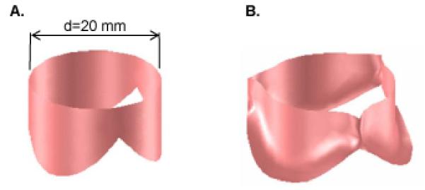
Geometry of the aortic valve model. (A) Three leaflets joined at the commissures and wrapped into a cylinder. (B) Three-leaflet mesh deformed by dilating the cylinder to which the constrained edges (lower edges and commissures) of the leaflets are attached.
Figure 3.
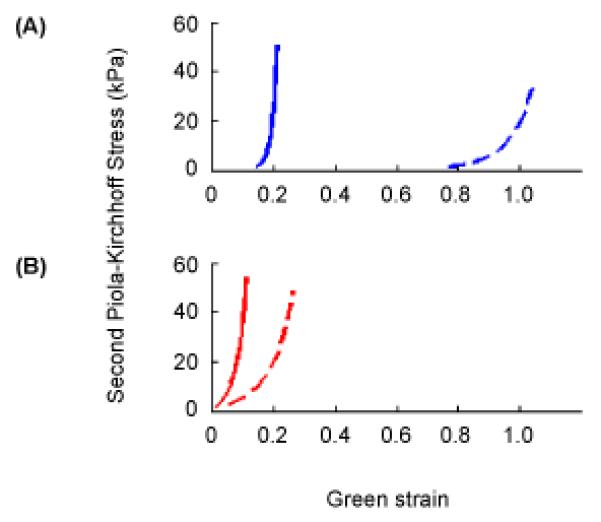
Stress versus strain curves described by Eqns. 1-3 corresponding to equibiaxial loading at 60 kPa Lagrangian stress in (A) normal human aortic valve leaflet tissue and (B) glutaraldehyde–treated bovine pericardium. On both sets of axes, the solid curve corresponds to the principal fiber direction in the tissue and the dashed curve to the perpendicular direction. Values of the seven model parameters, c and A1 – A6, are 9.7, 49.56, 5.29, −3.12, 16.03, −0.004, −0.02 for normal human aortic valve tissue and 3056, 25.46, 12.10, 5.07, 25.99, 0, 0 for glutaraldehyde-treated bovine pericardium, respectively.
In this study, we consider a surgical repair to be effective if the valve coapts normally under typical diastolic pressure of 80 mmHg. Since we are interested only in the state of the valve at peak pressure load, we neglect fluid flow and aortic root dynamics. We simulate aortic valve loading in two steps. First we treat the aortic root as an elastic tube, using published values of wall thickness and Young’s modulus (Grande et al., 1998), and we distend the root to its diameter at 80 mmHg. The final positions of the nodes where the leaflets attach to the root are determined by the force balance between transaortic pressure, aortic wall stress, and any forces due to constraints imposed by the leaflets. Then the nodes on the aortic root are held fixed, and 80 mmHg of pressure is applied to the aortic surface of the leaflets.
2.2 Biomechanics of valve leaflet tissue
Heart valve leaflets exhibit nonlinear, anisotropic in-plane response and minimal bending stiffness. We use the following constitutive law to approximate the in-plane response
| (1) |
where W is strain energy density, c is a constant and Q reprtesens the following combination of components of Green’s strain tensor
| (2) |
where Eij is Green’s strain tensor, i and j are indices representing the two principal directions, and the values A are experimentally determined constants. We use published values to describe native aortic valve leaflets (Billiar and Sacks, 2000) (Fig. 3a) and glutaraldehyde-treated pericardium (Sacks, 1999) (Fig 3b). The in-plane stress tensor is computed from the strain tensor as
| (3) |
where S is the second Piola-Kirchhoff stress.
2.3 Finite element simulation
We simulate the dynamics of the valve in order to predict its final deformed state under uniform pressure. We use a dynamic rather than static approach because it is computationally more straightforward and robust. We equate nodal forces due to pressure with the sum of internal (elastic), damping, and inertia forces, solving the resulting system of differential equations to update nodal positions. To calculate internal forces, we implemented a large deformation FE model based on three-node membrane elements. The method follows prior work modeling inflatable membranes (Taylor et al., 2005) that we have previously extended to heart valve leaflets (Hammer et al., 2011). Briefly, the local Green’s strain tensor is computed for each triangular element based on nodal positions in the present (deformed) and reference (undeformed) configurations. The strain tensor is rotated to the principal axes of the tissue as determined from published descriptions of the aortic valve leaflet fiber pattern (Sacks and Yoganathan, 2007). The stress tensor is computed from the strain tensor according to the constitutive law (1-3), and then the stress tensor is rotated back to the local (triangle) coordinate system. Internal forces are computed as
| (4) |
where A and H are area and thickness of the triangle in its original configuration, S is the 2nd Piola-Kirchhoff stress tensor, and B is the strain displacement matrix computed from nodal positions in both present and reference configurations.
Pressure loading is simulated by applying constant pressure of 80 mmHg to the aortic surface of all mesh triangles. Simulations are terminated when the incremental displacement of the middle of a leaflet free edge becomes small (< 10−5 mm).
2.4 Contact handling
Intra- and inter-leaflet contact arises during valve closure, so mesh-wide collision detection must be employed continually during simulation, requiring substantial computation. We use an efficient strategy that reduces the number of possible triangle pair collisions by maintaining sorted lists of axis-aligned bounding boxes of all triangles (Baraff, 1992). Then only those triangle pairs with overlapping bounding boxes are checked for triangle-to-triangle intersection. For an intersecting pair, contact force is applied to the vertices of one triangle that are found to intersect with the other triangle. The contact force acts perpendicular to the intersected triangle, and the magnitude is
| (5) |
where fext is the net external force acting on the node, d is the perpendicular distance between the node and the face of the intersected triangle (with positive values lying on the side toward which the normal vector points), k is contact stiffness, and h is distance beyond which contact force vanishes. This makes the reaction force on the node due to contact with the triangle balance the component of the force due to pressure driving the node toward the triangle. This prevents interpenetration and produces frictionless contact. Contact force vanishes quickly with increasing positive values of d then transitions smoothly to a linear penalty force for interpenetration, avoiding the high numerical stiffness that would result if the relationship were exponential for all d. We chose k = 10 N/m and h = 0.1 mm to achieve effective contact handling.
2.5 Solution Method
The equations of motion are discretized using a second-order backward difference method and solved using semi-implicit numerical integration (Hammer et al., 2008). We use adaptive time-step control based on step doubling (Press, 1986), using a target truncation error of 0.01 mm. The stabilized biconjugate gradient method (Barrett, 1994) is used to solve the sparse linear system. Computation is implemented in Matlab (Mathworks, Natick, MA), with computational bottlenecks like contact handling written in C.
2.6 Analysis of valve closure
A normal aortic valve of the size simulated in this study exhibits coaptation height of 3 to 4 mm at the valve center during diastole (Swanson and Clark, 1974). To quantify leaflet coaptation, we find the region on one of the native leaflets that lies within 0.5 mm (the approximate leaflet thickness) of an adjacent leaflet. Leaflet closure is then quantified by finding the minimum height of this contact region measured perpendicular to the free edge.
2.7 Experimental validation
Adult porcine hearts were obtained from an abattoir, and fresh porcine pericardium was harvested from sacrificed pigs. An aortotomy was made 1.5 – 2 cm distal to the coronary arteries. The noncoronary leaflet was excised and placed in phosphate buffered saline (PBS), and the free edge length and leaflet height were measured in the unstressed state (Fig. 4A). Pericardium was fixed in 0.625% glutaraldehyde solution for 3-5 minutes and rinsed in PBS. A leaflet graft was cut from pericardium in one of three sizes: graft height and width equal to those of the excised native leaflet (case W0H0) (n=3), free edge width 25% greater than excised native leaflet (case W25H0) (n=3), and both free edge width and leaflet height 25% greater than excised native leaflet (case W25H25) (n=3). A 1 mm suturing edge was added to all graft boundaries except the free edge. The graft was sutured along the noncoronary annulus (Fig. 4B), and the aortotomy was closed and coronary arteries ligated. To assess the repaired valve, we attempted to load the specimen with pressurized air at 80 mmHg (Fig. 4C) via tubing around which the distal aorta was cinched. If the repaired valve was competent under 80 mmHg of air pressure, the loaded valve was CT scanned (MicroCAT, Siemens, Munich, Germany). The image was segmented and meshed, and central coaptation height was measured on the 3d mesh of the closed valve using custom software (Fig. 4D). In cases where the repaired valve was not competent during application of pressurized air, it was generally not possible to achieve a stable state of valve closure for CT scanning. In these cases, pressurized water at 80 mmHg was connected to the distal aorta, and regurgitant flow was collected and measured.
Figure 4.
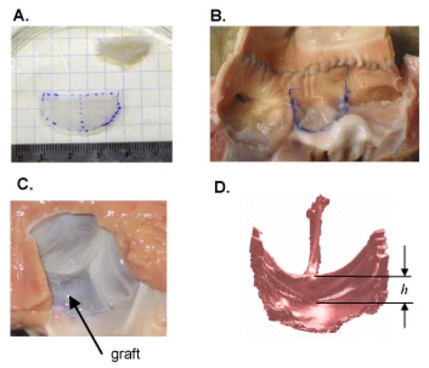
(A) Height and free edge width of leaflet graft were based on dimensions of excised non-coronary leaflet, with the unstressed state determined by floating leaflet on a thin layer of PBS. (B) Graft (middle leaflet) sewn to the noncoronary root. Note that this photo was taken after CT imaging, as axial incision of the aorta was necessary to acquire this view. (C) Left ventricular surface of the pressure-loaded aortic valve after the noncoronary leaflet was replace with a graft. (D) Surface rendering of a CT scan of repaired valve loaded with pressurized air at 80 mmHg. The minimum central coaptation height of repaired valve was determined by manually delineating the central coaptation height, h, on each of the three leaflets then choosing the minimum. All four panels correspond to one of the surgical repairs in which both graft height and free edge width were 25% greater than the native leaflet that was excised (case W25H25).
3 Results
3.1 Simulation
Simulations of a normal valve (three identical leaflets with constitutive laws for native leaflet tissue) predicted leaflets meeting in the axial center of the root (Fig. 5A, columns 1 and 2). The coaptation region on a leaflet is bounded by the free edge, the two commissures, and curves from the bottom of the commissures to a point along the leaflet midline that lies approximately 3 mm below the free edge (Fig. 5A, column 3). Simulations were then run with one leaflet replaced by a pericardial graft. The width and height of the graft were varied across all combinations of five widths (0, 7, 14, 21 and 27% greater than native leaflet width) and four heights (0, 13, 27 and 40% greater than native leaflet height). For each combination, the coaptation region for one of the native leaflets was computed, and minimum coaptation height was calculated (Fig. 6).
Figure 5.
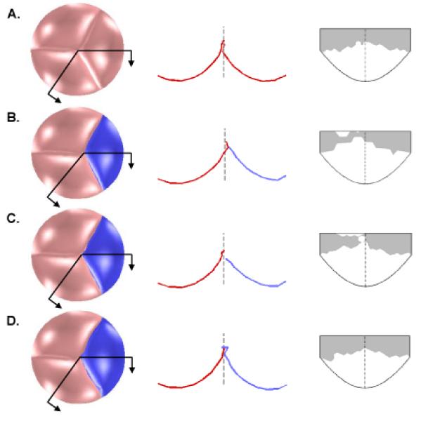
Results of finite element simulations showing the effect of pericardium graft size on aortic valve closure. First column shows the bottom view of the closed valve loaded with 80 mmHg of pressure. Second column shows the intersection of the leaflets with the two cut planes indicated in the first column, with the dashed line showing the axial center of the valve. In the third column, the coaptation region of a native leaflet is shown in gray, mapped onto an outline of the leaflet in the undeformed configuration. Row A depicts a normal valve (three native leaflets). Row B depicts a valve with one normal leaflet replaced with a pericardial graft (shown darker and in blue) of equal size to the native leaflet. Row C depicts a valve with a graft equal in height but 7% wider than the native leaflet. Row D depicts a valve with a graft 27% higher and 21% wider than the native leaflet.
Figure 6.
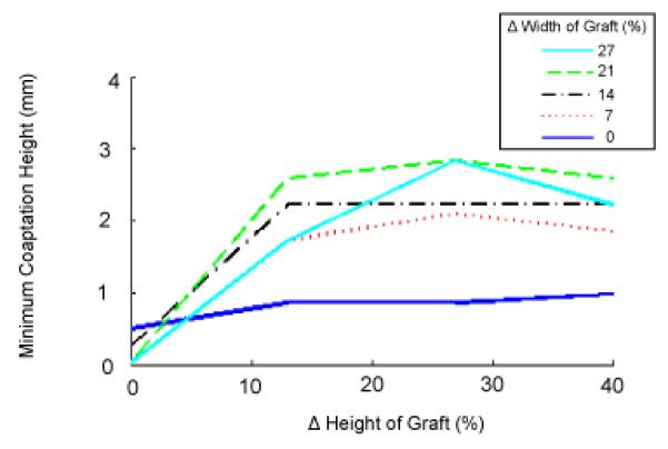
Effect of pericardial leaflet graft width and height on leaflet coaptation. Graft dimensions are expressed in percent increase relative to the width and height of the native leaflet.
For a pericardial leaflet graft of the same size as the native leaflet, simulation shows an asymmetrical valve in the loaded state, with the leaflet graft unable to distend to the axial center of the aortic root (Fig. 5B, columns 1 and 2). The minimum coaptation height is less than 1 mm (Fig. 5, column 3 and Fig. 6). As graft width is increased holding graft height constant, coaptation gets worse, as the pressure-loaded graft slides along the two native leaflets toward the left ventricle rather than extending toward the axial center of the aortic root (Fig. 5C and Fig. 6, intersection of all curves with vertical axis). This failure of the leaflets to completely coapt results in a central gap in the simulated closed valve which would correspond to AR in an actual valve. As graft height is increased holding width constant, the graft is overly constrained due to inadequate free edge length and low distensibility parallel to the free edge. Consequently, coaptation is incomplete or marginal (minimum coaptation height < 1 mm) for all graft heights (Fig. 6, dark blue solid line). As graft width and height are simultaneously increased relative to native leaflet dimensions, coaptation improves, reaching a maximum of 3 mm for a graft 27 % higher and 21-27 % wider than the native leaflets (Fig. 5D and Fig. 6). As graft width is further increased, coaptation worsens as the excess graft material slides downward past the native leaflets.
3.2 Experimental validation
Of the nine aortic valve preparations, only the three from case W25H25 were competent under 80 mmHg of air pressure. From the resulting CT images, the minimum central coaptation heights in the three preparations were 4.9, 2.7 and 4.3 mm. For cases W0H0 (n=3) and W25H0 (n=3), the valves were incompetent under 80 mmHg of air pressure (Fig. 7), so we measured retrograde flow of water at 80 mmHg through the incompetent valve. Mean flow for case W0H0 was 5.0 +/− 3.0 ml/sec and for case W25H0 was 16.8 +/− 15.9 ml/sec (Table 1).
Figure 7.
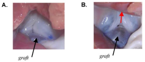
(A) Photograph looking up the left ventricular outflow tract at the isolated porcine aortic valve in which the noncoronary leaflet was replaced with a pericardium graft equal in size to the excised native leaflet (case W0H0). Photo was taken during application of 80 mmHg of air pressure. The valve was incompetent with a small central gap and regurgitant air flow. (B) Photograph looking up the left ventricular outflow tract at the incompetent isolated porcine aortic valve in which the noncoronary leaflet was replaced with a pericardium graft 25% wider than the excised native leaflet (case W25H0). Photo was taken during application of 80 mmHg of air pressure. Valve was incompetent, with a large (visible) central gap and substantial regurgitant air flow (direction indicated by red arrow).
Table 1.
Regurgitant flow through isolated porcine aortic valves following single leaflet replacement with pericardium. Flow was determined by using a reservoir of water at height corresponding to 80 mmHg of pressure to load the distal end of the excised aorta. Efflux through the valve was collected over 60 seconds. The first row (W0H0) corresponds to the case where both the free edge width and height of the graft were equal to corresponding dimensions of the native (noncoronary) leaflet that was excised (n=3). The second row (W25H0) corresponds to the case where the height of the graft was 25% greater than that of the native (noncoronary) leaflet that was excised (n=3).
| Dimensions of leaflet graft | Regurgitant flow (ml/sec) | Mean +/− SD (ml/sec) |
|---|---|---|
| W0H0 | 1.6, 7.3, 6.1 | 5.0 +/− 3.0 |
| W25H0 | 13.8, 34.0, 2.7 | 16.8 +/− 15.9 |
4 Discussion
The primary goal of this study was to use a FE model of aortic valve leaflets to inform the repair of the aortic valve using autologous pericardium. Simulating leaflet grafts in a range of widths and heights showed that the decreased distensibility of treated pericardium relative to native leaflet tissue necessitates oversizing the width and height of the graft relative to native leaflet dimensions in order to achieve proper closure. Furthermore, simulations reveal a complex relationship between graft size and repair effectiveness which may help explain the difficulty developing robust guidelines for the sizing of leaflet grafts. Sizing the graft equal to that of the native leaflet results in complete, although marginal, coaptation, and increases in free edge width alone worsen coaptation. The graft must be significantly larger in both height and width to achieve normal coaptation and robust repair.
The graft sizing guidelines suggested by simulations agree with our clinical observations and are corroborated by our experiments. Both experimental cases W0H0 and W25H0 result in retrograde flow under 80 mmHg of pressure (Table 1). Furthermore, there was a trend toward greater retrograde flow in case W25H0, and a photo of the partially pressurized valve (Fig. 7B) shows that the graft slid below the native leaflets as predicted by simulation (Fig. 5C, column 2). Case W25H25 results in an effective seal and normal degree of central leaflet coaptation (Section 3.2). Work by others has shown that coaptation height increases to a maximum then decreases in response to increasing sinotubular junction diameter (Maselli et al., 2007). Although they varied valve diameter and not leaflet width, their results corroborate our findings that for proper coaptation, leaflets must be wide enough relative to the vessel diameter to meet the opposing leaflets but not so wide that they slide toward the left ventricle under load.
Lim et al used the FE method to predict the effect of pericardial graft shape on aortic valve function (Lim et al., 2004). However, they neglected the nonlinear anisotropic behavior of valve tissue and only simulated replacement of all three leaflets with identical grafts, limiting the applicability of their results to axially symmetrical valve repairs. Our method allows extension of predictive modeling to the clinically important case of single leaflet replacement.
We model the native leaflets and pericardium as membranes, assuming negligible flexural stiffness. This is supported by data showing bending stresses at least an order of magnitude smaller than in-plane stresses (Merryman et al., 2006; Vesely and Boughner, 1989). We have not assessed the validity of the membrane assumption for diseased leaflets, which can be thickened and calcified. Our study is limited to valve function at peak diastole, but altering graft size could affect flow through the valve during systole. Finally, in order to study general design principles involved in constructing pericardial grafts, we have simulated a generic aortic valve design. By building meshes of the leaflets and root directly from pre-operative ultrasound, we could adapt our method to produce patient-specific simulations for surgical planning.
Acknowledgements
This work was supported by grant R01 HL073647 from the NIH.
Footnotes
Publisher's Disclaimer: This is a PDF file of an unedited manuscript that has been accepted for publication. As a service to our customers we are providing this early version of the manuscript. The manuscript will undergo copyediting, typesetting, and review of the resulting proof before it is published in its final citable form. Please note that during the production process errors may be discovered which could affect the content, and all legal disclaimers that apply to the journal pertain.
Conflict of Interest Statement
We have no financial or personal conflicts of interest to disclose.
REFERENCES
- Bacha EA, McElhinney DB, Guleserian KJ, Colan SD, Jonas RA, del Nido PJ, Marx GR. Surgical aortic valvuloplasty in children and adolescents with aortic regurgitation: acute and intermediate effects on aortic valve function and left ventricular dimensions. J Thorac Cardiovasc Surg. 2008;135(3):552–9. doi: 10.1016/j.jtcvs.2007.09.057. 559.e1-3. [DOI] [PubMed] [Google Scholar]
- Baraff D. Dynamic simulation of nonpenetrating rigid bodies; Doctoral dissertation; Cornell University, Ithaca, NY. 1992. [Google Scholar]
- Barrett R. Templates for the solution of linear systems: building blocks for iterative methods. Siam; Philadelphia: 1994. p. 112. [Google Scholar]
- Billiar KL, Sacks MS. Biaxial mechanical properties of the natural and glutaraldehyde treated aortic valve cusp--Part I: Experimental results. J Biomech Eng. 2000;122(1):23–30. doi: 10.1115/1.429624. [DOI] [PubMed] [Google Scholar]
- De Hart J, Peters GW, Schreurs PJ, Baaijens FP. A three-dimensional computational analysis of fluid-structure interaction in the aortic valve. J Biomech. 2003;36(1):103–112. doi: 10.1016/s0021-9290(02)00244-0. [DOI] [PubMed] [Google Scholar]
- Duran CM, Gometza B, Kumar N, Gallo R, Martin-Duran R. Aortic valve replacement with freehand autologous pericardium. J Thorac Cardiovasc Surg. 1995;110(2):511–516. doi: 10.1016/S0022-5223(95)70248-2. [DOI] [PubMed] [Google Scholar]
- Gnyaneshwar R, Kumar RK, Balakrishnan KR. Dynamic analysis of the aortic valve using a finite element model. Ann Thorac Surg. 2002;73:1122–1129. doi: 10.1016/s0003-4975(01)03588-3. [DOI] [PubMed] [Google Scholar]
- Grande KJ, Cochran RP, Reinhall PG, Kunzelman KS. Mechanisms of aortic valve incompetence: finite element modeling of aortic root dilatation. Ann Thorac Surg. 2000;69(6):1851–1857. doi: 10.1016/s0003-4975(00)01307-2. [DOI] [PubMed] [Google Scholar]
- Grande KJ, Cochran RP, Reinhall PG, Kunzelman KS. Stress variations in the human aortic root and valve: the role of anatomic asymmetry. Ann Biomed Eng. 1998;26(4):534–545. doi: 10.1114/1.122. [DOI] [PubMed] [Google Scholar]
- Grande-Allen KJ, Cochran RP, Reinhall PG, Kunzelman KS. Finite-element analysis of aortic valve-sparing: influence of graft shape and stiffness. IEEE Trans Biomed Eng. 2001;48(6):647–659. doi: 10.1109/10.923783. [DOI] [PubMed] [Google Scholar]
- Hammer PE, Vasilyev NV, Perrin DP, del Nido PJ, Howe RD. Fast image-based model of mitral valve closure for surgical planning; MIDAS Journal, Computational Biomechanics for Medicine (MICCAI 2008 Workshop); 2008.pp. 15–26. [Google Scholar]
- Hammer PE, Sacks MS, del Nido PJ, Howe RD. Mass-spring model for simulation of heart valve tissue mechanical response. Ann Biomed Eng. 2011;39(6):1668–1679. doi: 10.1007/s10439-011-0278-5. [DOI] [PMC free article] [PubMed] [Google Scholar]
- Jonas RA. Aortic valve repair for congenital and balloon-induced aortic regurgitation. Seminars in Thoracic and Cardiovascular Surgery. Pediatric Cardiac Surgery Annual. 2010;13(1):60–65. doi: 10.1053/j.pcsu.2010.01.001. [DOI] [PubMed] [Google Scholar]
- Kim H, Chandran KB, Sacks MS, Lu J. An experimentally derived stress resultant shell model for heart valve dynamic simulations. Ann Biomed Eng. 2007;35(1):30–44. doi: 10.1007/s10439-006-9203-8. [DOI] [PubMed] [Google Scholar]
- Kim H, Lu J, Sacks MS, Chandran KB. Dynamic simulation of bioprosthetic heart valves using a stress resultant shell model. Ann Biomed Eng. 2008;36(2):262–275. doi: 10.1007/s10439-007-9409-4. [DOI] [PubMed] [Google Scholar]
- Labrosse MR, Beller CJ, Robicsek F, Thubrikar MJ. Geometric modeling of functional trileaflet aortic valves: development and clinical applications. J Biomech. 2006;39(14):2665–2672. doi: 10.1016/j.jbiomech.2005.08.012. [DOI] [PubMed] [Google Scholar]
- Labrosse MR, Lobo K, Beller CJ. Structural analysis of the natural aortic valve in dynamics: from unpressurized to physiologically loaded. J Biomech. 2010;43(10):1916–1922. doi: 10.1016/j.jbiomech.2010.03.020. [DOI] [PubMed] [Google Scholar]
- Lim KH, Candra J, Yeo JH, Duran CM. Flat or curved pericardial aortic valve cusps: a finite element study. J Heart Valve Dis. 2004;13(5):792–797. [PubMed] [Google Scholar]
- Maselli D, De Paulis R, Scaffa R, Weltert L, Bellisario A, Salica A, Ricci A. Sinotubular junction size affects aortic root geometry and aortic valve function in the aortic valve reimplantation procedure: an in vitro study using the Valsalva graft. Ann Thorac Surg. 2007;84(4):1214–8. doi: 10.1016/j.athoracsur.2007.05.035. [DOI] [PubMed] [Google Scholar]
- Merryman WD, Huang HY, Schoen FJ, Sacks MS. The effects of cellular contraction on aortic valve leaflet flexural stiffness. J Biomech. 2006;39(1):88–96. doi: 10.1016/j.jbiomech.2004.11.008. [DOI] [PubMed] [Google Scholar]
- Nicosia MA, Cochran RP, Einstein DR, Rutland CJ, Kunzelman KS. A coupled fluid-structure finite element model of the aortic valve and root. J Heart Valve Dis. 2003;12(6):781–789. [PubMed] [Google Scholar]
- Press WH. Numerical Recipes: the art of scientific computing. Cambridge University Press; Cambridge Cambridgeshire; New York: 1986. p. 818. [Google Scholar]
- Ranga A, Mongrain R, Biadilah Y, Cartier R. A compliant dynamic FEA model of the aortic valve; 12thIFToMM World Congress; Bensancon, France. 2007. [Google Scholar]
- Sacks MS. A method for planar biaxial mechanical testing that includes in-plane shear. Journal of Biomechanical Engineering. 1999;121(5):551–555. doi: 10.1115/1.2835086. [DOI] [PubMed] [Google Scholar]
- Sacks MS, Yoganathan AP. Heart valve function: a biomechanical perspective. Philos Trans R Soc Lond B Biol Sci. 2007;362(1484):1369–1391. doi: 10.1098/rstb.2007.2122. [DOI] [PMC free article] [PubMed] [Google Scholar]
- Sun W, Abad A, Sacks MS. Simulated bioprosthetic heart valve deformation under quasi-static loading. J Biomech Eng. 2005;127(6):905–914. doi: 10.1115/1.2049337. [DOI] [PubMed] [Google Scholar]
- Swanson M, Clark RE. Dimensions and geometric relationships of the human aortic valve as a function of pressure. Circ Res. 1974;35(6):871–882. doi: 10.1161/01.res.35.6.871. [DOI] [PubMed] [Google Scholar]
- Taylor RL, Oñate E, Ubach P. Finite Element Analysis of Membrane Structures. In: Onate E, Kroplin B, editors. Textile Composites and Inflatable Structures. Springer; The Netherlands: 2005. [Google Scholar]
- Thubrikar M. The aortic valve. CRC Press; Boca Raton: 1990. p. 221. [Google Scholar]
- Vesely I, Boughner D. Analysis of the bending behaviour of porcine xenograft leaflets and of natural aortic valve material: bending stiffness, neutral axis and shear measurements. J Biomech. 1989;22(6-7):655–671. doi: 10.1016/0021-9290(89)90016-x. [DOI] [PubMed] [Google Scholar]
- Xiong FL, Goetz WA, Chong CK, Chua YL, Pfeifer S, Wintermantel E, Yeo JH. Finite element investigation of stentless pericardial aortic valves: relevance of leaflet geometry. Ann Biomed Eng. 2010;38(5):1908–1918. doi: 10.1007/s10439-010-9940-6. [DOI] [PubMed] [Google Scholar]


