Abstract
In recent years post-processing of fast multi-slice MR imaging to correct fetal motion has provided the first true 3D MR images of the developing human brain in utero. Early approaches have used reconstruction based algorithms, employing a two step iterative process, where slices from the acquired data are re-aligned to an approximate 3D reconstruction of the fetal brain, which is then refined further using the improved slice alignment. This two step slice-to-volume process, although powerful, is computationally expensive in needing a 3D reconstruction, and is limited in its ability to recover sub-voxel alignment. Here, we describe an alternative approach which we term slice intersection motion correction (SIMC), that seeks to directly co-align multiple slice stacks by considering the matching structure along all intersecting slice pairs in all orthogonally planned slices that are acquired in clinical imaging studies. A collective update scheme for all slices is then derived, to simultaneously drive slices into a consistent match along their lines of intersection. We then describe a 3D reconstruction algorithm that, using the final motion corrected slice locations, suppresses through-plane partial volume effects to provide a single high isotropic resolution 3D image. The method is tested on simulated data with known motions and is applied to retrospectively reconstruct 3D images from a range of clinically acquired imaging studies. The quantitative evaluation of the registration accuracy for the simulated data sets demonstrated a significant improvement over previous approaches. An initial application of the technique to studying clinical pathology is included, where the proposed method recovered up to 15 mm of translation and 30 degrees of rotation for individual slices, and produced full 3D reconstructions containing clinically useful additional information not visible in the original 2D slices.
I. Introduction
One of the greatest challenges of fetal MRI has been unconstrained fetal motion. Before fast MR sequences were developed, pharmaceutical approaches were taken to sedate the subject, for example, by administering benzodiazepines to the mother [1], [2] or pancuronium bromide directly to the fetus [3], [4]. The introduction of fast MR techniques has dramatically changed the use of fetal MRI. Fast MR sequences applicable to fetuses include echo-planar imaging (EPI) [5], single-shot methods such as half-Fourier acquisition single-shot turbo spin-echo (HASTE) and single shot fast spin echo (SSFSE) [6].
Since these sequences are typically rapid snapshot 2D acquisitions with enhanced contrast, they are acquired as a stack of 2D slices to cover a 3D space [7]. Although fast 2D MR images of the fetus provide insights into fetal brain anatomy, their application is limited to clinical diagnosis or qualitative studies [8], because unconstrained fetal motion can occur between the acquisition of different slices, which distorts the 3D interpretation of the anatomy. While there are several studies on human brain development using volumetric approaches, the scope of the studies covered mainly neonates [9]–[11], or post-mortem fetal subjects [12]. Recent studies on human brain development of fetuses using 2D MR slices can be found in [13]–[15]. The first automated tissue segmentation of developing tissues from motion corrected un-sedated fetal brain anatomy was recently described in utero [16] following the development of 3D reconstruction techniques [17]–[19].
It has been shown that stacks of multiple 2D slices can be used to build a 3D volume of the fetal brain [17], [18]. In the work, three orthogonally planned stacks of 3 mm thick slices were registered by slice-to-volume registration, where the volume was iteratively constructed by the putative estimation of the motion parameters in each iteration. Normalized mutual information (NMI) was employed for the similarity measure of registration, and Gaussian weighted averaging was used for reconstruction. In [20], a similar approach was taken, but using a multiple stacks in a single orientation for both registration and reconstruction. The method was generalized to a wider spectrum of applications including neonates and adults, where the motion correction problem is simplified by the lack of confounding maternal tissue structures. However, unlike earlier techniques where standard clinically acquired orthogonal acquisitions are used to form a 3D volume, the single slice orientation approach is limited in its ability to recover accurate through-plane geometry for cases of through-plane movements. A single slice orientation approach is also not compatible with standard radiological practice, where orthogonal slices need to be acquired for interpretation.
All the approaches above, where the evaluation of the similarity measure is indirectly related to the motion parameters through the reconstruction step, have specific limitations: First, the registration involves the reconstruction of the volume in each iteration, which is computationally intensive. Second, the reconstruction step in the evaluation of the similarity measure slows down the convergence of the optimization. Third, the recovered motion parameters are dependent on the reconstruction method. The approach in [19] has achieved the reconstruction-free registration via matching the intersections between each of two orthogonally planned slice pairs, considering all possible pairings of slices within the multiple slice stacks. This approach defines an energy function as the mean square difference (MSD) [21] between slices. The optimization is simplified by deriving the gradient of the energy function with respect to the motion parameters. In this formulation, the derivatives are functions of the spatial intensity gradient of the 2D images, and have good analytical properties. The complexity of the proposed approach is O(N2M), where N stands for the number of slices and M the 1D size (width or height) of the slices, which is a substantial reduction from O(N2M2) of the existing methods.
In this paper, we present a full description of the approach which we term slice intersection motion correction (SIMC), to both register stacks of clinical 2D MR scans acquired for the human fetal brain and reconstruct a 3D volume that is consistent with the 2D slices. Section II introduces a basic geometry of 2D planes in the 3D space, as well as the energy function of the optimization problem. Section III describes the actual implementation of the optimization and the procedure for the 3D reconstruction from the motion compensated slices. The proposed methods are evaluated by using 3D post-mortem fetal imaging from which motion-corrupted 2D slice stacks are simulated, and by applying the methods to a range of clinically fetal data sets. The results are presented in Section IV.
II. Methods
In this work, we start with the assumption that Q stacks of multiple 2D MR images are acquired through the fetal brain anatomy. We additionally assume that sets of stacks of these images are planned in three approximately orthogonal directions (axial, sagittal and coronal). During the acquisition of the slice stacks, the fetus moves within the mother. We assume the time for the acquisition of a single slice is short compared to the motion of the fetus, and therefore, for the majority of the slices, the images represent geometrically correct anatomy. However, due to the motion of the fetus, and the time required to acquire multiple slices, significant motion can occur both between the acquisition of the stacks and between the acquisition of the slices within a stack. For this reason, the true location of each slice with respect to the fetal anatomy is unknown. We parametrize the location and orientation of the i-th slice in the subject coordinate system by θi. Here we consider the intersection of slices in stacks that are planned in approximately orthogonal directions (e.g. for axially planned slices, this will include all the slices in coronally and sagittally planned stacks). For simplicity, we denote all the acquired slices in all the stacks by I1, ···, IN, and, in all the acquired stacks, the set of slices that the i-th slice can intersect with by Si.
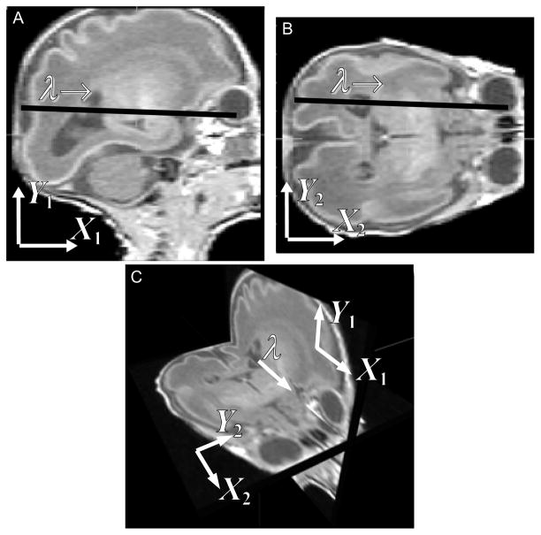
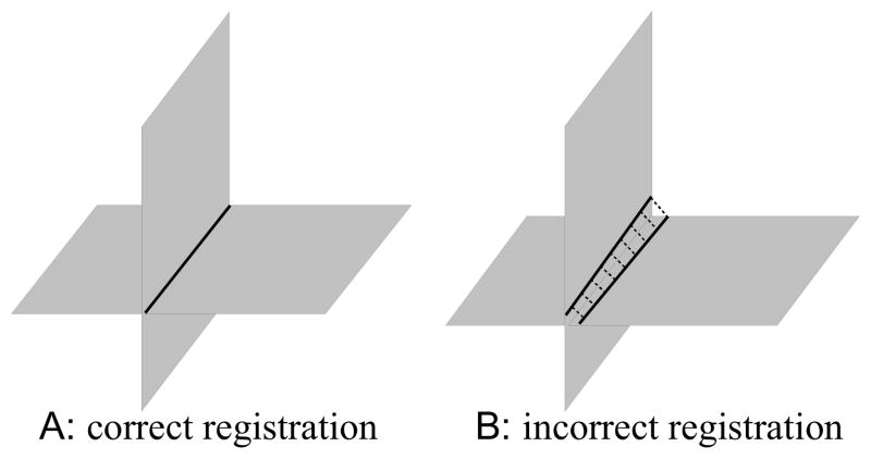
The motion estimation problem to be solved is to find the motion parameters θ1, ···, θN that bring the slices back into collective alignment with each other. The proposed solution to this problem is based on the direct slice-to-slice matching approach [19]. When two orthogonally planned slices have an intersection and they are correctly aligned, the intersecting slices should have identical intensity profiles along their intersection. When they are misaligned, as shown in Fig. 1, their profiles do not match, the motion correction can be carried out by manipulating the transformation parameters to improve the match of the two profiles.
Fig. 1.
When two orthogonally planned slice stacks cover a common volume, each slice in one stack always intersects with the slices in the other stack. A sagittal slice (A) and an axial slice (B) from simulated MR image stacks of a premature infant are shown. Panel A and B are viewed in the 3D space in panel C. Two slices can be registered by adjusting the transformation parameters so as to improve the match of their intersection intensity profiles.
Note that intersections are matched across slice stacks. Slices from one orientation sometimes have intersections among themselves and they can also contribute to the registration. However, these intersections are not considered, because they often disappear depending on the relative slice motion, yielding a discontinuity in the energy function. The registration makes use of the intersections between orthogonally planned slices only, as opposed to those slices planned to be parallel. For example, the motion of axial slices is recovered using coronal and sagittal slices, and so is the case for coronal or sagittal stacks.
In the context of matching 2D slices of the same MRI sequence, we assume the MRI contrasts are identical and, unlike matching a slice to the reconstructed volume, images have similar levels of blurring, which allows the use of difference based dissimilarity measures in the alignment. Here we use a spatially weighted mean square intensity difference (MSD) of the signal between slices, unlike the normalized mutual information (NMI) in [18] or the cross-correlation (CC) in [20]. In this problem, the weighted MSD energy function provides more constraints by forcing similar intensity values in two images to correspond during registration, and hence can provide improved capture range and a reduced chance of falling into local minima.
A. Coordinate system
At the beginning of the procedure, one of the stacks is manually or automatically chosen to be the reference stack. The coordinate system of the center slice in the reference stack is used as the reference coordinate system, or the subject coordinate system. A floating coordinate system is defined for each of the slices. The floating frame of a slice is related to the reference frame by
| (1) |
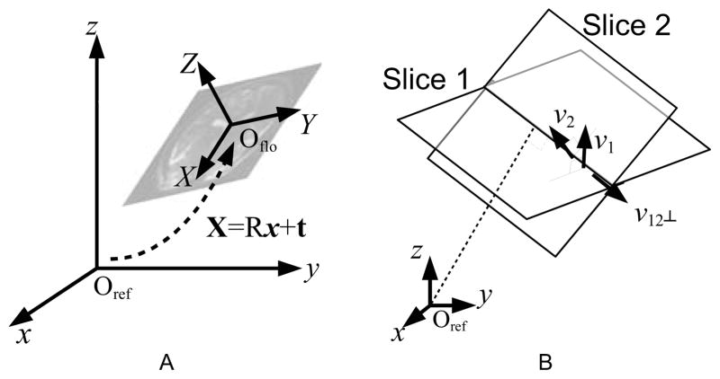
where X represents the position vector in the floating frame, x the position vector in the reference frame, R a 3-by-3 rotation matrix, and t a translation vector, respectively (Fig. 2A). Since the plane of the slice is defined to be the XY-plane of its floating frame, the equation of the slice plane in the reference frame is obtained from the third component in (1),
Fig. 2.
(A) The reference frame, and the floating frame of one slice. The two coordinate systems are related by six motion parameters—three for translation (t) and three for rotation (R). (B) Parametrization of the intersection location. The parameter λ is 0 at the projection of the origin of the reference space onto the intersection line, and increases as it extends along the intersection direction, namely, v12⊥
| (2) |
where v, the normal vector of the plane, is the transpose of the third row of R, namely, v⊤ = R3,*.
For any two non-parallel planes, there exists an intersection line that is a subset of both planes. The line can be parametrized by λ;
| (3) |
where v12⊥ = v1 × v2/|v1 × v2| is the unit vector pointing to the direction of the intersection line (Fig. 2B). The mapping equations of this intersection line from the reference frame to the floating frames of the two slices are then
| (4) |
| (5) |
Since X1z and X2z are 0 in the floating frames, the third components of (4) and (5) are,
| (6) |
| (7) |
Thus, g and h of (3) are found;
| (8) |
| (9) |
B. Energy Function
The fetal motion is estimated by finding the motion parameters (θ1, ···, θN ) that minimize the global energy function E, which is defined by the combined dissimilarity of the intersection profiles between all combinations of any two orthogonally planned slices, e.g. an axially planned slice vs. a coronally planned slice, etc;
| (10) |
where N denotes the total number of slices, Si the set of slices in the stacks orthogonally planned to the i-th slice, Ii the i-th slice image, and θi the set of the motion parameters of the i-th slice, namely, θi = [tix tiy tiz θix θiy θiz ]⊤, respectively. The dissimilarity measure Dij is defined between two intersecting slices i and j, drawn from two orthogonally planned stacks,
| (11) |
As mentioned earlier, the registration energy function to be minimized is chosen to be the MSD of the intensity profiles between two slices which are spatially weighted using a windowing function wij to exclude maternal tissues (described in further detail in the following sections) and averaged over all intersections of orthogonally planned slices,
| (12) |
where the vector Xi(λ; θi, θj) is a position vector in the i-th image, along the intersection between the i-th and j-th images parametrized by λ, as defined in (4) and (5), and Nw = Σi,jΣλ∈Ii∩Ij wij (λ) is the normalization factor. The complete energy function is, thus,
| (13) |
The partial derivative of (12) with respect to a motion parameter, namely θi is
| (14) |
Thus, ∂
 /∂θi is a function of the two slice images, the spatial derivatives of the images, and the variation of the location of the intersection line within the two slices with respect to the motion parameter θi, which can be found in Appendix A.
C. Fetal Head Windowing
One of the challenges of the rigid fetal brain tissue registration problem is the influence of deforming maternal tissues that surround the fetal head. This is particularly important because these regions can contain high contrast boundaries (due, for example, to amniotic fluid) that can dominate the response of the registration measure and lead to poor alignment of slices that contain smaller proportions of brain tissue. The influence of these tissues can be addressed by delineating the brain from all slices beforehand [20], [22]. However, such a process is much more complex than skull striping in adult brain anatomy and is difficult to reliably automate for 2D T2W fetal slice data containing maternal tissues.
No spatial windowing was used in [18] except for an approximate rectangular bounding box. In [19], the intersection profile is weighted by a cosine bell window given by, , where λ0 and λ1 are adjusted to fit the bell shape to the intersection line segment. However, this approach does not account for the true 3D form of the fetal head, and still allows the contribution of matching non-fetus signals when matching two intersections at the edge of the brain. It also provides a poor window for highly misaligned slice pairs. Critically, being defined in the intersection coordinate frame, there is no way of enforcing anatomical consistency in the aperture between slice pairs.
Thus, it is a more natural choice to use the 3D windowing function to exclude the contribution of the non-fetal head tissues. In this work we have used a true 3D model based spatial windowing approach using an approximate model for the rigid fetal head anatomy. We define this spatial region of interest in a consistent 3D coordinate system related to the average space of the slice stacks as their alignment evolves, which provides a weighting to reduce the influence of deforming maternal tissues.
An ideal windowing function would be the exact aperture with the shape of the fetal head, or at least an average of fetal head images. However, the detailed shape and size of the brain can differ significantly between fetuses. As a reasonable approximation for the purpose of spatial windowing, we have used a parametric model consisting of an ellipsoid that is defined within the field of view of the subject;
| (15) |
where
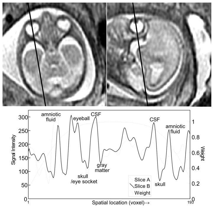
 (x) is the 3D ellipsoid volume to constrain the location of the fetal brain, and λ is related to the spatial location by (3). Figure 3 is an example of the intersection profile between an axial and a sagittal slice of a fetus at 22 weeks of gestational age, and the windowing function along the intersection.
Fig. 3.
The intersection between two orthogonally planned slices. (GA 22 weeks under normal development, TR/TE = 4500/90.) The bottom panel shows the two intersection profiles of the slices, and 1D profile of the 3D ellipsoidal windowing function.
D. Parametrized motion estimation
The goal of the registration is to recover the exact motion of the fetus imposed on each slice acquisition. A motion parameter value at a time point is strongly correlated with other parameter values in its temporal neighborhood, particularly when the fetus undergoes a smooth motion.
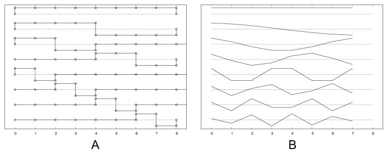
The work in [18] took this property into account by grouping temporally adjacent slices together, and splitting the groups into half in the process of registration. The benefit of this grouping includes the reduced dimensionality and the suppression of local minima. This grouping scheme, i.e., to group the parameters into one, two, then four groups etc., can be represented by the Haar basis set (Fig. 4A). The Haar basis set, however, is not the ideal function to represent the fetal motion, which is rather smooth. Even when sudden motion occurs, there is no guarantee that the moment of the sudden motion matches the splitting of the Haar basis functions.
Fig. 4.
Basis functions for motion estimation: (A) Haar basis functions and (B) discrete cosine basis functions.
In this work, accounting for slice interleave, we parametrize the motion using a discrete cosine basis set (Fig. 4B), and compare the performance with the existing grouping scheme. We use the type II discrete cosine basis functions;
| (16) |
or, in a vector-matrix formulation,
| (17) |
where the Bm,n corresponds to the motion parameter of the m-th slice of the n-th discrete cosine basis function, and θk and αk are the vectors of the motion parameters in temporal order and the coefficients of the discrete cosine representation, respectively, in the k-th translational or rotational direction.
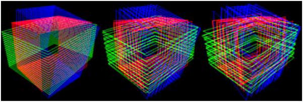
The optimization starts with a small number of basis functions to provide an approximate estimate, and the number of the basis functions is gradually increased for higher accuracy. For the Haar basis functions, the number of the basis functions is doubled at the moment of basis increment, while the number of the discrete cosine basis functions can be increased one by one without losing symmetry. An example of parametrized motion compensation using the discrete cosine functions is viewed in Fig. 5, where the number of basis functions per stack was 1, 9 and 23 from the left to the right.
Fig. 5.
Visualization of motion parametrization using the discrete cosine functions. From the left, the number of basis functions for each stack is 1, 9 and 23, respectively.
III. Implementation
When only two slices are aligned by matching the intersection intensity profiles, the registration determines only 5 parameters out of 6, leaving one rotational degree of freedom undetermined. This is comparable to two hinge flaps free to rotate around the common joint. In order to achieve a unique registration of slices, at least 3 slices are needed, one orthogonally planned with respect to the others so that the singularity in determining the relative motion parameters is removed. The proposed approach, likewise, makes use of at least 3 stacks that are orthogonally planned with respect to one another.
A. Data preprocessing
Fetal MR images are acquired using a standard clinical imaging protocol which uses a conventional single shot fast spin-echo (SSFSE) T2W sequence. These may be gated for maternal breathing and include within-stack replanning by the radiologist to adjust the slice orientations using a real time planning tool when the fetus has moved severely during the acquisition of a stack of slices. Two or three stacks are acquired from each of three orientations—axial, sagittal and coronal. The original slice has 512×512 of voxels with 0.5×0.5 mm2 in-plane dimensions. The fetal brain occupies about 100×100 voxels of area, and the rest is filled with maternal organs. A simple rectangular region encompassing the brain and surrounding tissues is manually selected in the reference stack (typically the first axial stack). The corresponding regions in other stacks are then located by matching the stack against the ROI in the reference stack through a global rigid body transformation [23]. The stacks are cropped around this rectangular reference volume, allowing a 20% of margin on each side to encompass the brain under severe motion. The motion parameters from the initial global rigid body transformations between stacks are used for the initial motion parameters for the following registration procedure. The intersection profiles of voxel intensity values are constructed by resampling the image slices using 2D B-spline interpolation within plane.
B. Motion parametrization during optimization
The energy function is minimized by the Levenberg-Marquardt method;
| (18) |
where D is the lexicographical representation of the weighted intensity differences along the intersections between all the combinations of orthogonally planned slice pairs, θ the lexicographical representation of the motion parameters, namely, , and thus, .
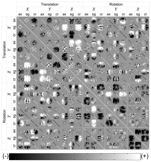
Note that the first order approximation of the Hessian matrix in (18) is the covariance matrix of θ. Figure 6 is an example of the covariance matrix of the intersection profiles of three orthogonally planned stacks. This figure demonstrates the relationship of the dissimilarity measure of registration and the relative location and orientation of each slice. In this figure, it is identifiable that each slice transformation parameter is correlated with all other slice transformation parameters, including both across stack and within stack, directly or indirectly. For example, the X translation of the sagittal stack (X, sg) is positively correlated with Z translation of the coronal stack (Z, cr).
Fig. 6.
An example of the approximated Hessian matrix, calculated for the registration of three orthogonally planned stacks. Axial, sagittal and coronal stacks are denoted by ax, sc and cr, respectively. The translation of a slice in one stack is correlated with the translation of the slices from other stacks. The correlation between a translation and a rotation can be both (+) and (−) within one stack, depending on which side in the stack a slice is located with respect to the center slice of the stack. The rotation-rotation correlation can be identified likewise. Grid lines are added for reading.
When the motion is parametrized by (17), (18) can be rewritten as
| (19) |
In this formulation, one may drop higher degree dimensions of the basis function set in order to reduce the dimensionality of the Hessian matrix, and also to disregard physically unrealistic high frequency motion, as described in II-D. By implementing the Levenberg-Marquardt optimization for lower degree motion, and the conjugate gradient descent for higher degree motion, we achieve the optimal computational efficiency.
C. Exclusion of individual mis-matched slices for reconstruction
After the slice alignment optimization is complete, although most of the slices converge to their common consensus, some of the slices remain poorly matched. Those slices arise for cases of image degradation by fetal motion during the slice acquisition, partial volume effect (PVE), or from other imaging artifacts in the slice. Such slices are automatically detected by the abnormal level of their mean square intensity difference with respect to all other intersecting slices, evaluated in the spatial window region of the fetal head. A threshold level above which slices are classed as abnormal is defined with respect to the median mean square intensity difference (MSD) for all slices in a stack. The threshold level was empirically set to 1.25 times the median slice MSD in the stack. These rejected slices occurred in less than 1% of the clinical data.
D. Reconstruction by gradient-weighted averaging
While the possibility of super-resolution in MR imaging has been under debate [24]–[28], the reconstruction of a high resolution 3D volume from multiple 2D slices with anisotropic voxel dimensions, which is a super-resolution problem in the classical sense [29], is feasible. In this problem, the low through-plane resolution of one stack is complemented by the in-plane resolution of other stacks planned orthogonally to the stack. Since the in-plane images are sampled beyond the Nyquist rate of the through-plane acquisition in a typical multislice MR image acquisition, the reconstruction resolution in the through-plane dimension is restricted by the Nyquist limit of the in-plane resolution instead of the limit of the through-plane. This image fusion can be achieved by an interpolation of non-uniform sampling points.
In [20], a multilevel scattered data interpolation method using an iterative B-spline interpolation was employed. The point spread function (PSF) weighted averaging method in [18] is a non-iterative approach, which incorporates the information on the image acquisition model. In our work, the reconstruction in [18] is developed to selectively reduce the relative contribution of 2D slice pixels with greater PVE.
Since a typical 2D fetal MR image acquisition has anisotropic voxel dimensions, the amount of PVE varies depending on the relative angle of the image slice with respect to the direction of the underlying tissue boundaries. In general, the voxel of a 2D MR image is a cuboid elongated in the through-plane direction. Voxels in a slice plane parallel to a tissue boundary are more inclined to include multiple tissue types than those in a slice which is perpendicular to the boundary as depicted in Fig. 7.
Fig. 7.
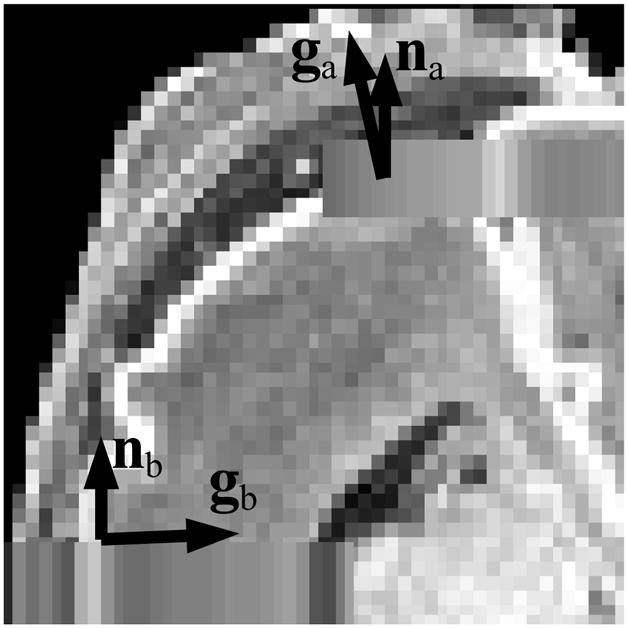
A diagram depicting the through-plane partial volume effect. When the direction of tissue transition (g) is parallel to the normal vector of the slice (n), the voxel at that location may include contributions from different tissue types. When g is close to being perpendicular to n, the voxel at that location is less likely to include different tissue types.
In order to suppress PVE in the reconstructed volume, we penalize the voxels that do not distinguish different tissue types. The degree of PVE is evaluated from the relative angle of the voxel orientation and the direction of intensity gradient in the region of anatomy, namely θvg. Fortunately, although the true 3D intensity gradient at the acquired voxel location is unknown, one does not need the true 3D gradient to determine the selective weighting factor, if we weight the voxel on the slice in proportion to |sin θvg|, as shown in the following paragraph.
The relationship between the true 3D gradient g and the 2D gradient at its corresponding point on the i-th slice, , is given by
| (20) |
where n̂i is the normal vector of the i-th slice plane. Given the weight of the voxel on the i-th slice is proportional to |sin θvg| = |g ×n̂i|, the gradient weighting of the corresponding voxel on the i-th slice is the magnitude of the 2D gradient;
| (21) |
Finally, the gradient weighting term is combined with the PSF weighted averaging method, and the resulting estimate of the intensity in the 3D reconstruction is given by
| (22) |
where I(x) is the reconstructed voxel value at x, PSF the point spread function in the 2D floating frame, and Ii the acquired slice image, and the subscript i denotes slice index. The spatial transformation is defined by Ti(x) = Rix + ti as in (1), and represents the closest point on the i-th plane to Ti(x), the transformed location of x.
IV. Results
A challenge in testing the proposed methods is that there is no ground truth available in in utero fetal brain imaging. In earlier work [18] we made use of related premature neonatal imaging where a full T1W 3D acquisition was available (GA=28 weeks and older), from which simulated 2D acquisitions with motion artifacts could be created. This approach to validation was also replicated in the later work of [30] and then in [20] using T2W 3D images of a premature neonate (GA=30 weeks) and adult images. The key limitations of this approach to simulation are the difference in image contrast between typical T2 weighted fetal imaging and T1 weighted 3D neonatal imaging, the absence of confounding maternal tissues and also the differences in the developmental ages of the premature neonate and the fetus. To provide a more realistic evaluation of the fetal brain imaging problem, in this work we have made use of high quality post-mortem T2 weighted imaging of a fetal brain at an early stage of brain folding development to which we added 2D motion artifacts and contributions from surrounding maternal tissues acquired from in vivo studies. As in [18], a set of simulated motion-corrupted 2D slice stacks were formed using this data to simulate in utero imaging during fetal motion independent of maternal tissues, but with known slice motion parameters. In addition to this simulation, the methods were tested on clinical scans, and the reconstructed volumes were visually inspected.
A. Synthesizing clinical 2D studies from Post-mortem 3D MRI
True 3D fetal imaging data used to evaluate the accuracy of registration method consisted of a fast relaxation fast spin echo (FRFSE) sequence acquired as a 3D T2W volume with TR = 3000 ms and TE = 82.8 ms, and voxel dimensions = 0.59×0.59×1 mm3, using a 3T system (GE Medical Systems, Milwaukee, Wis.). The fetus had gestational age (GA) of 21.28 weeks.
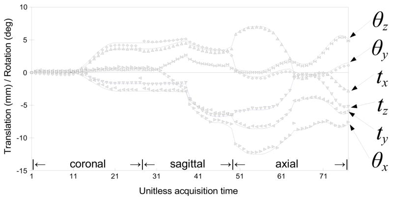
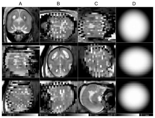
In each simulated study, three orthogonal stacks are generated, and each stack consists of multiple slices of 1×1×3 mm3 voxel dimensions with no overlap, yielding 3-fold effective overlap from 3 stacks. Fetal motion was simulated by adding two motion points during the simulated acquisition of each stack, where the amount of motion is randomly chosen within a preset range. The motion was temporally smoothed using a Gaussian kernel for physical reality (Fig. 9). The air region of the post-mortem scan was replaced by maternal structures that were extracted from an in utero scan. Sets of 2D slices rotated and translated to simulate the head motion trajectory were generated and the maternal tissues surrounding the fetal head were kept fixed to provide a realistic confound for the registration algorithm. The PVE of the lower resolution clinical scans was simulated by applying spatial blurring the volume with a 3D Gaussian kernel, with σs proportional to the resampling voxel dimensions. A set of simulated stacks is shown in Fig. 8A–C.
Fig. 9.
Fetal motion was simulated by adding two motion points during the simulated acquisition of each stack, where the amount of motion is randomly chosen within a preset range. The motion was then temporally smoothed using a Gaussian kernel for physical reality (solid lines). The symbols indicate the estimated motion parameters obtained by registering slices using the proposed method.
Fig. 8.
Example motion corrupted slice stacks created from post-mortem fetal brain image data of a terminated pregnancy at GA 21.28 weeks, resampled in three different orientations with simulated fetal motion and maternal tissues added. Axial (A), sagittal (B) and coronal (C) stacks are generated with 22 slices in each orientation, and with voxel dimensions 1×1×3 mm3. (D) The 3D ellipsoidal spatial windowing function used select brain tissues during alignment.
In total, 100 data sets with different levels of fetal motion were generated. The simulated stack sets were then registered by the proposed methods, using three different approaches of spatial windowing and trajectory parametrization: (A) Intersection based 1D cosine bell spatial windowing along the intersection line and Haar basis functions for motion parametrization, (B) Full 3D ellipsoidal spatial windowing and Haar basis functions, (C) Full 3D ellipsoidal spatial windowing and the discrete cosine basis functions.
The registration accuracy against the ground truth for the synthesized data was evaluated by calculating the slice intersection error (SIE). This can be derived by considering two slices that intersect: With the correct estimate of the movement of the fetal brain, the sampling points on the two intersecting line segments have zero separation (Fig. 10A). If the estimated motion deviates from the ground truth, the sampling points on the intersection line segments will be separated from one another (Fig. 10B), where the separation between a pair of sampling points can be evaluated. The SIE between two slices i and j is derived from Eqs. (3)–(5) and defined by
Fig. 10.
Measurement of the registration error between two slices. (A) Two slices are correctly registered, the true intersection lines have zero separation. (B) The registration is incorrect, two intersection lines are separated. The slice intersection error (SIE) is the square of this separation, averaged over all sampling points.
| (23) |
where superscript * and ∧ denote the estimated transformation and the ground truth, respectively.
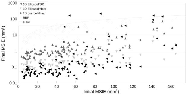
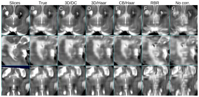
In order to evaluate the registration accuracy of the entire stack set, the mean slice intersection error (MSIE) was computed for all slice intersections. Figure 11 is the comparison of the MSIE before and after the registration. In this result, the proposed slice intersection motion correction (SIMC) method is shown to perform better than the existing reconstruction based registration (RBR) method. In particular in terms of accuracy, SIMC using a full 3D ellipsoid windowing approach together with a discrete cosine (DC) motion parametrization provides the lowest error. In terms of the robustness or capture range for larger fetal movements, this combination also outperforms other approaches. An illustration of one of the reconstructed volumes from the simulated test data sets is shown in Fig. 12.
Fig. 11.
The Mean Slice Intersection Errors (MSIEs) of the proposed registration method, using three different conditions (Full 3D ellipsoid/discrete cosine (DC), Full 3D ellipsoid/Haar, and 1D cosine bell weighted motion compensation/Haar motion basis functions) are plotted in mm2 along with the existing reconstruction based registration (RBR) method. The x- and y-axes represent the initial and the final MSIE. Stacks of a post-mortem fetal brain image from a terminated pregnancy at GA 21.28 weeks were used, resampled in three different orientations with simulated fetal motion and maternal tissues.
Fig. 12.
A comparison between (A) original in-plane views of the stacks with simulated fetal motion of Fig. 8 and reconstructed volumes, with (B) ground truth motion parameters, (C) full 3D ellipsoid weighted motion compensation/discrete cosine motion basis functions, (D) full 3D ellipsoid weighted/Haar, (E) 1D cosine bell weighted/Haar, (F) reconstruction based motion compensation, and (G) no motion compensation. The mean slice intersection error was B:0.00, C:0.04, D:0.99, E:1.03, F:23.01 and G:34.87 mm2, respectively.
B. Retrospective 3D image formation from clinical fetal MRI data
We applied the SIMC method to reconstruct 3D images retrospectively from clinically acquired fetal imaging studies carried out at UCSF. This is a challenging and realistic data set that, unlike the work of [20], does not make use of careful pre-processing to remove maternal tissues but instead focuses on the retrospective use of algorithms on clinically standard imaging protocols. The imaging data consisted of single-shot fast spin-echo (SSFSE) T2-weighted image sets of fetuses, acquired during normal maternal breathing using a 1.5T system (GE Medical Systems, Milwaukee, Wis.). Each stack typically consists of between 20 to 30 slices, acquired with an interleave of two. The repetition time (TR) ranged from 3000–11000 ms, and the echo time (TE) 86–100 ms. The in-plane resolution was approximately 0.5×0.5 mm2, and the slice thickness was 3 mm. The subjects were 34 fetuses with gestational ages ranging from 20 to 34 weeks, under normal development. Eleven of the subjects had two scanning time points, so in total 45 separate data sets were used in the test. The mean and median of the GA at the moment of scan were 23.43 and 25.60 weeks, respectively. The original scans often include multiple stacks in each orientation, but up to 2 stacks were used in the test for a fair comparison. Each data set is preprocessed as described in subsection III-A. A full 3D ellipsoid function was employed for spatial windowing of the registration, and the discrete cosine basis functions were used for motion parametrization.
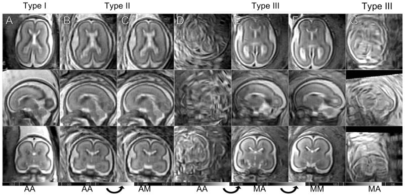
In total 45 data sets are visually inspected by a pediatric neuroradiologist with specific expertise in fetal MRI (OG) to confirm that gray matter (GM), white matter (WM), germinal matrix (GMat; a tissue type observed during a short period in development) and cerebrospinal fluid (CSF) are separable and their signal intensities fall into a consistent range over the entire image. The algorithm provided very accurate reconstructions in 24 cases without any form of manual intervention (Type i). On 10 other data sets, the algorithm provided a visually acceptable reconstructions, but with local regions of artifacts due to the presence of misregistered outlier slices (Type ii). For these data sets, the outlier slices are manually marked after investigating using a visualization tool instead of the slice rejection criterion described in subsection III-C. For the remaining 11 data sets, the algorithm did not provide a visually acceptable reconstruction automatically (Type iii). For these studies, it was found that for 9 of them, manual reinitialization of stack motion parameters which were highly misaligned, combined with a re-run on the algorithm, provided high quality 3D reconstructions. This indicated that for these small fraction of cases the capture range of the algorithm was not adequate to recover motion for some slices. The types of reconstruction are counted and presented in Table I, and examples of the types are shown in Fig. 13.
TABLE I.
Registration/reconstruction results of in utero fetal brain scans.
| Type | Initialization | Slice Selection | Count |
|---|---|---|---|
| (i) | Automatic | Automatic | 24 |
| (ii) | Automatic | Manual | 10 |
| (iii) | Manual | Automatic | 2 |
| Manual | Manual | 7 | |
| Failed | 2 | ||
| Partially failed | 2 | ||
| Total | 45 | ||
Fig. 13.
Reconstruction results of subjects at similar ages. (A) GA = 22.3 wks (B–C) GA = 22.4 wks (D–F) GA = 22.7 wks (G) GA = 22.4 wks. The data set in G column completely failed even with the manual initialization. AA: Automatic initialization, automatic slice selection, AM: Automatic initialization, manual slice selection, MA: Manual initialization, automatic slice selection, MM: Manual initialization, manual slice selection.
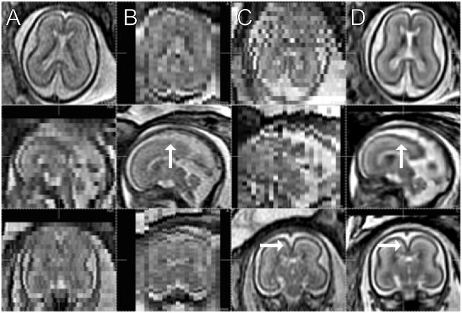
Figure 14A–C display views in axial, sagittal, and coronal stacks, of one of the subjects at 22 weeks of GA, and Fig. 14D the reconstructed volume in the corresponding cross sections. Note that the through-plane distortion is removed, and the noise is reduced in the reconstructed volume. In addition a number of anatomical structures are more clearly defined in the reconstructed volume than in the original 3 mm slice data, for example, the gray matter region which appears degraded in the original stacks (arrows).
Fig. 14.
The original stacks in 3 different orientations, (A) axial, (B) sagittal, and (C) coronal. (GA 22 weeks under normal development, TR/TE = 4500/90.) (D) Reconstructed volume in the corresponding cross sections. (2 axial stacks (23 and 21 slices), 2 sagittal (19 and 19) and 2 coronal (23 and 23) are used. Automated initialization and slice selection.)
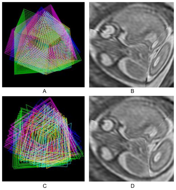
The behavior of individual slices is depicted in Fig. 15. Before the registration, the edges of the slices are aligned (Fig. 15A) while the brain anatomy and the eyeballs appear misaligned (Fig. 15B). After the registration, the tissue types are now aligned (Fig. 15D) returning the anatomy to correct correspondence (Fig. 15C).
Fig. 15.
Three dimensional visualization of the slices. (A) The edges of individual slices from six stacks are shown in the initial configuration after rigid stack alignment. (B) Three orthogonally planned slices in the initial configuration after rigid stack alignment. (C) The edges after motion compensation. (D) The same slices after motion compensation
After the registration, outlier slices that are either degraded or initially badly misregistered are excluded by the automated procedure described in III-C, using a thresholding factor=1.25. A few examples of degraded outlier slices in the coronal direction are depicted in Fig. 16 in comparison with a normal coronal slice. The normal slice in Fig. 16A shows clear separation between CSF (white), GM (black) and WM (gray), while these structures are blurred or darkened in the degraded slices. For 17 of the data sets in the experiment for which the automated procedure failed to reject all outlier slices, the slices were manually excluded using a 3D slice visualization tool.
Fig. 16.
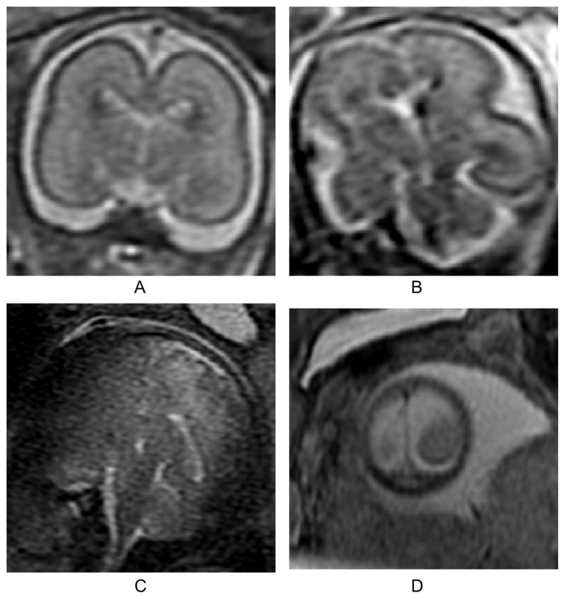
Examples of a normal slice (A), a slice degraded by motion during the slice acquisition occurring in-plane (B), through-plane (C), and through-plane partial volume effect for a slice at the edge of the brain (D). In our experience, the occurrence of these artifacts is less than 1% of the acquired slices in our clinical studies. All planes shown are coronal.
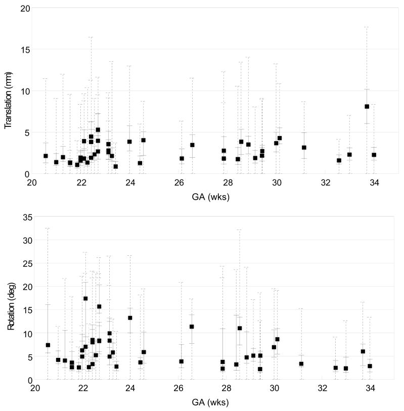
Figure 17 depicts the amount of slice motion compensation in translation (top panel) and rotation (bottom panel) estimated for each subject as a function of the GA, after the outlier exclusion. The medians of the magnitude of the translation and rotation are marked by filled circles, along with the quartile range and the full range in a solid and a dashed line, respectively. Note that the proposed method recovers up to 15 mm (equivalent to 5 slices) of translation, and 30 degrees of slice rotation. However, no noticeable dependence of the amount of motion on GA was observed in this study.
Fig. 17.
The distribution of the magnitude of the recovered slice translation (top) in mm and rotation (bottom) in degrees for all studies, plotted as a function of the gestational age (GA). The median magnitude of each study is marked by a filled circle, along with the quartile range in a solid line and the full range in a dashed line. These results show the ability of the algorithm to recover significant motion of the fetal head during the imaging.
C. An Example of Clinical Applications
In order to provide an initial clinical evaluation of the utility of the approach, comparative image analysis procedures were applied to original and motion corrected data. Data from a study of a fetal brain with agenesis of the corpus callosum (ACC) (GA=24.57 wks, TR/TE=8000/91.168) and a normal fetal brain (GA=24.00wks, TR/TE=6666/90.432) at a similar GA were studied. The subjects were scanned using the scanner described in IV-B with the voxel dimensions of 0.47×0.47×3.00 mm3.
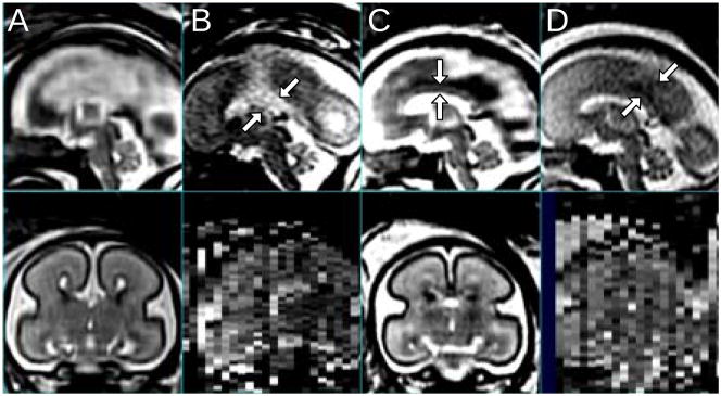
Figure 18 illustrates both the original data, the 3D reconstructions and the improvement in interpretation of the data made possible by a true 3D reconstruction. Acquisition of a true mid-sagittal slice with real time planning is a considerable challenge and depends on the movement of the fetus during the study. After the 3D reconstruction it is possible to easily select a mid-sagittal slice from the volume between the left and right lobes of the brain to inspect the midline anatomy as shown in Fig. 18. When such a slice is located, either CSF or GM and WM will be found in the mid-plane between the hemispheres indicating the severity of the corpus callosum abnormality as shown in Fig. 18B, D. Here, CSF filling the central fissure of the ACC brain is visualized as the bright region in the sagittal view in the top panel. In the normally developing anatomy, the corpus callosum, including fine detail of the connecting white matter and grey matter is visible in the slice in the 3D volume reconstruction of Fig. 18C. In particular, the same features are not visible in the original slice (Fig. 18D), due to both the greater noise and partial volume effects in the single acquired 2D slice data.
Fig. 18.
Sagittal and coronal views of the MR images of a fetal brain with agenesis of the corpus callosum (A,B; GA=24.57 wks, TR/TE=8000/91.168) and a normal control fetus (C,D; GA=24.00 wks, TR/TE=6666/90.432). (A) The motion compensated 3D reconstruction, and (B) the raw clinically acquired sagittal slice stack. Arrows indicate the central fissure filled with CSF. (C) The motion compensated 3D reconstruction with the corpus callosum marked with arrows, and (D) the raw clinically acquired sagittal slice stack, where arrows indicate GM on the mid-plane between the left and right lobes.
As an example of the utility of the 3D reconstructions to study tissue surfaces in 3D, Fig. 19 shows the result of automatic segmentation [16] applied before (top) and after motion compensation (bottom) of images of a normal subject scan, where each column corresponds to the volume rendering of GM, WM, GMat (germinal matrix) and the ventricle, respectively (GA=23.14 wks). While the surfaces without motion correction display shape distortion as well as tissue discontinuities in the GMat, the motion corrected volumes provide anatomically realistic smooth surfaces for this early stage of development. Such segmentation techniques allow the quantitative evaluation of surface folding in fetuses [31].
Fig. 19.
The result of automatic segmentation [16] before (top) and after the motion compensation (bottom). From left to right, each column corresponds to the volume rendering of GM, WM, GMat and the ventricle, respectively (GA=23.14 wks).
V. Discussion and Conclusion
In this paper, we presented a procedure to automatically register slice stacks of fetal MR images, and reconstruct a high isotropic resolution 3D volume that is consistent with the original slice stacks. Matching the intersections between slices provided a direct measure to evaluate the mismatch between slices. By defining an optimization energy function as the weighted mean square difference (wMSD) of intersection intensity profiles, we reformulated the registration problem into a conventional optimization problem, which was solved by combination of the Levenberg-Marquardt and conjugate gradient methods. The confounding influence of maternal tissues was suppressed by a spatial windowing function on the registration measure. A motion parametrization was introduced to reduce computational cost and constrain the registration to physically realistic fetal motion. Finally, we also proposed a novel volume reconstruction technique that adds a gradient based weighting to the existing Gaussian weighting method, in order to penalize voxels degraded by partial volume effect. This was achieved by comparing the relative orientation of voxel alignment with respect to the direction of tissue boundaries in the images.
The slice alignment method has been shown to provide improved accuracy in the recovery of known fetal motion, by using a high resolution post-mortem fetal brain image data set to which simulated motion and maternal tissue artifacts were added. The quantitative evaluation of the registration accuracy was achieved by comparing the slice intersection error (SIE), and this indicates that the proposed method consistently achieves the subvoxel accuracy. For example, when the initial MSIE was varied by up to 60 mm2, the method recovered alignment to within 0.1 mm2 or better of the ground truth in more than 75% of cases.
The method was then extensively evaluated on a large cohort of clinically acquired fetal brain data sets using visual inspection by an expert radiologist. The result of the test on the clinical data sets showed that the approach, combined with a quick slice initialization step before registration and a slice rejection step prior to reconstruction, provided better than 90% success when applied retrospectively to a range of clinical data. The algorithm recovered up to 15 mm of translation and 30 degrees of rotation for individual slices in this evaluation. For the most challenging studies with extreme motion, a semi-automatic procedure was applied which included stack location initialization, and slice rejection after alignment to remove a small number of unmatched slices after registration and prior to 3D volume reconstruction. The reasons for failure to align some individual slices include noise, inhomogeneous bias field, partial volume effect for slices cutting through the edge of the brain and fetal motion during the acquisition of a slice. These caused the algorithm to match incorrect tissue types together, for example, CSF-skull-amniotic fluid to WM-GM-CSF, because those tissue types have similar T2 response. However these cases can be easily excluded, either automatically or manually.
The proposed reconstruction method can achieve both improved signal to noise by averaging multiple 2D studies and improved resolution by increasing the through-plane resolution up to that of the in-plane resolution. This is achieved by penalizing the contribution of partial-volumed slices, i.e., slices that are parallel to a tissue boundary. The subvoxel motion correction accuracy provided by our new approach will allow the incorporation of improved 3D super-resolution approaches such as those of [32].
The proposed method provides two important advantages: improved 3D resolution to delineate finer scale structures of the fetal brain, and improved signal-to-noise ratio (SNR) by averaging multiple scans to provide a superior delineation of subtle contrasts between developing tissues. Currently, assessment of fetal structures using clinical fetal MRI can be challenging since it is extremely difficult to obtain true orthogonal planes that allow accurate assessment of important brain structures, due to fetal motion. Being able to better evaluate important structures, such as the midline, corpus callosum and cortex, will allow more accurate identification and quantification of fetal brain abnormalities and therefore result in improved prenatal counselling.
Acknowledgments
This work is primarily funded by NIH Grant R01 NS 055064 (PI: C. Studholme) and the data used in the retrospective analysis was funded by K23 NS52506 (PI: O. Glenn). The contents of the paper are solely the responsibility of the authors and do not necessarily represent the official views of the NIH. Dr. Rousseau received funding from the European Research Council under the European Community Seventh Framework Programme (FP7/2007-2013 Grant Agreement no. 207667). The authors would also like to thank Dr. Roland Henry for advice on the imaging protocols and assistance with the transfer of imaging data.
Appendix A
Partial Derivatives
The mapping from the floating frame of a slice to the reference frame is a function of the motion parameters of the slice, and this is mediated by g and h, which are also functions of the motion parameters as well, as formulated in (4) and (5). The partial derivatives of the mapping functions (4) and (5) with respect to the motion parameters are derived below.
For translations,
| (24) |
| (25) |
| (26) |
For the rotation around the k-axis,
| (27) |
| (28) |
where the apostrophe (′) denotes the partial derivative in the k-direction. The change of the mapping position in the floating frame caused by the change of the motion parameters is,
| (29) |
| (30) |
| (31) |
| (32) |
| (33) |
| (34) |
where v1⊥ is a unit vector that is normal to both v1 and v12⊥, namely,
| (35) |
| (36) |
The partial derivatives of X2 are derived in the same manner.
Contributor Information
Kio Kim, Email: kio.kim, Department of Radiology and Biomedical Imaging, University of California San Francisco CA, 94143 USA. (Website: http://radiology.ucsf.edu/bicg).
Piotr A. Habas, Email: pi-otr.habas, Department of Radiology and Biomedical Imaging, University of California San Francisco CA, 94143 USA. (Website: http://radiology.ucsf.edu/bicg).
Francois Rousseau, Email: rousseau@lsiit.u-strasbg.fr, LSIIT, UMR 7005 CNRS/ULP, Illkirch, 67412 France.
Orit A. Glenn, Email: orit.glenn, Department of Radiology and Biomedical Imaging, University of California San Francisco CA, 94143 USA. (Website: http://radiology.ucsf.edu/bicg)
Anthony J. Barkovich, Email: jimb@radiology.ucsf.edu, Department of Radiology and Biomedical Imaging, University of California San Francisco CA, 94143 USA. (Website: http://radiology.ucsf.edu/bicg)
Colin Studholme, Email: colin.studholme@ucsf.edu, Department of Radiology and Biomedical Imaging, University of California San Francisco CA, 94143 USA (Website: http://radiology.ucsf.edu/bicg).
References
- 1.Weinreb J, Lowe T, Cohen J, Kutler M. Human fetal anatomy: MR imaging. Radiology. 1985;157:715–720. doi: 10.1148/radiology.157.3.3903856. [DOI] [PubMed] [Google Scholar]
- 2.Lowe T, Weinreb J, Santos-Ramos R, Cunningham F. Magnetic resonance imaging in human pregnancy. Obstet Gynecol. 1985;66:629–623. [PubMed] [Google Scholar]
- 3.Horvath L, Seeds J. Temporary arrest of fetal movement with pancuronium bromide to enable antenal magnetic resonance imaging of hologrosencephaly. Am J Perinatol. 1989;6:418–420. doi: 10.1055/s-2007-999629. [DOI] [PubMed] [Google Scholar]
- 4.Lenke R, Persutte W, Nemes J. Use of pancuronium bromide to inhibit fetal movement during magnetic resonance imaging. J Reprod Med. 1989;34:315–317. [PubMed] [Google Scholar]
- 5.Mansfield P, Stehling M, Ordidge R, Coxon R, Chapman B, Blamire A, Gibbs P, Johnson I, Symonds E, Worthington B, Coupland R. Echo planar imaging of the human fetus in utero at 0.5T. Br J Radiol. 1990;63:833–841. doi: 10.1259/0007-1285-63-755-833. [DOI] [PubMed] [Google Scholar]
- 6.Levine D, Barnes P, Sher S, Semelka R, Li W, McArdle C, Worawattanakul S, Edelman R. Fetal fast MR imaging: Reproducibility, technical quality, and conspicuity of anatomy. Radiology. 1998;206:549–554. doi: 10.1148/radiology.206.2.9457211. [DOI] [PubMed] [Google Scholar]
- 7.Glenn O, Barkovich A. Magnetic resonance imaging of the fetal brain and spine: An increasingly important tool in prenatal diagnosis, Part 2. American Journal of Neuroradiology. 2006 Oct;27:1–8. [PMC free article] [PubMed] [Google Scholar]
- 8.Perkins L, Hughes E, Srinivasan L, Allsop J, Glover A, Kumar S, Fisk N, Rutherford M. Exploring cortical subplate evolution using magnetic resonance imaging of the fetal brain. Developmental Neuroscience. 2008;30:211–220. doi: 10.1159/000109864. [DOI] [PubMed] [Google Scholar]
- 9.Rodriguez-Carranza C, Mukherjee P, Vigneron D, Barkovich J, Studholme C. A system for measuring regional surface folding of the neonatal brain from MRI. Proc. Medical Image Computing and Computer Assisted Intervention (MICCAI’06); 2006. [DOI] [PubMed] [Google Scholar]
- 10.Rodriguez-Carranza C, Mukherjee P, Vigneron D, Barkovic A, Studholme C. A framework for in-vivo analysis of regional brain folding in premature neonates. Neuroimage. 2008;41:462–478. doi: 10.1016/j.neuroimage.2008.01.008. [DOI] [PMC free article] [PubMed] [Google Scholar]
- 11.Dubois J, Benders M, Cachia A, Lazeyras F, Leuchter RHV, Sizonenko S, Borradori-Tolsa C, Mangin J, Hüppi PS. Mapping the early cortical folding process in the preterm newborn brain. Cerebral Cortex. 2008;18:1444–1454. doi: 10.1093/cercor/bhm180. [DOI] [PubMed] [Google Scholar]
- 12.Kinoshita Y, Okudera T, Tsuru E, Yokota A. Volumetric analysis of the germinal matrix and lateral ventricles performed using MR images of postmortem fetuses. Am J Neuroradiol. 2001;22:382–388. [PMC free article] [PubMed] [Google Scholar]
- 13.Kazan-Tannus JF, Dialani V, Kataoka ML, Chiang G, Feldman HA, Brown JS, Levine D. MR Volumetry of Brain and CSF in Fetuses Referred for Ventriculomegaly. Am J Roentgenol. 2007;189(1):145–151. doi: 10.2214/AJR.07.2073. [DOI] [PMC free article] [PubMed] [Google Scholar]
- 14.Hatab MR, Kamourieh SW, Twickler DM. MR volume of the fetal cerebellum in relation to growth. J Magn Reson Imaging. 2008 Apr;274:840–5. doi: 10.1002/jmri.21290. [DOI] [PubMed] [Google Scholar]
- 15.Hatab MR, Zaretsky MV, Alexander JM, Twickler DM. Comparison of fetal biometric values with sonographic and 3D reconstruction MRI in term gestations. American Journal of Roentgenology. 2008 Aug;191:340–345. doi: 10.2214/AJR.07.2623. [DOI] [PubMed] [Google Scholar]
- 16.Habas P, Kim K, Rousseau F, Glenn O, Barkovich A, Studholme C. Atlas-based segmentation of the germinal matrix from in-utero clinical MRI of the fetal brain. Proc. Medical Image Computing and Computer Assisted Intervention (MICCAI’08); September 2008; pp. 351–358. [DOI] [PMC free article] [PubMed] [Google Scholar]
- 17.Rousseau F, Glenn O, Iordanova B, Rodriguez-Carranza C, Vigneron D, Barkovich A, Studholme C. A novel approach to high resolution fetal brain MR imaging. Proc. Medical Image Computing and Computer Assisted Intervention (MICCAI’05); 2005. pp. 548–555. [DOI] [PubMed] [Google Scholar]
- 18.Rousseau F, Glenn OA, Iordanova B, Rodriguez-Carranza CE, Vigneron D, Barkovich JA, Studholme C. Registration-based approach for reconstruction of high-resolutionin utero MR brain images. Academic Radiology. 2006;13(9):1072–1081. doi: 10.1016/j.acra.2006.05.003. [DOI] [PubMed] [Google Scholar]
- 19.Kim K, Hansen M, Habas P, Rousseau F, Glenn O, Barkovich A, Studholme C. Intersection based registration of slice stacks to form 3D images of the human fetal brain. Proc. IEEE International Symposium on Biomedical Imaging (ISBI’08); 2008. pp. 1167–1170. [Google Scholar]
- 20.Jiang S, Xue H, Glover A, Rutherford M, Rueckert D, Hajnal J. MRI of moving subjects using multislice snapshot images with volume reconstruction (SVR): Application to fetal, neonatal, and adult brain studies. IEEE Transactions on Medical Imaging. 2007 Jul;26(7):967–980. doi: 10.1109/TMI.2007.895456. [DOI] [PubMed] [Google Scholar]
- 21.Hajnal J, Saeed N, Soar E, Oatridge A, Young I, Bydder G. A registration and interpolation procedure for subvoxel matching of serially acquired MR images. Journal of Computer Assisted Tomography. 1995;19(2):289–296. doi: 10.1097/00004728-199503000-00022. [DOI] [PubMed] [Google Scholar]
- 22.Guizard N, Lepage C, Fonov V, Hakyemez H, Evans A, Limperopoulos C. Development of fetus brain atlas from multi-axial MR acquisitions. Proc. Intl. Soc. Mag. Reson. Med. (ISMRM’08); 2008. p. 672. [Google Scholar]
- 23.Studholme C, Hill D, Hawkes D. An overlap invariant entropy measure of 3D medical image alignment. Pattern Recognition. 1999;32:71–86. [Google Scholar]
- 24.Peled S, Yeshurun Y. Superresolution in MRI: Application to human white matter ber tract visualization by diffusion tensor imaging. Magnetic Resonance in Medicine. 2001;45:29–35. doi: 10.1002/1522-2594(200101)45:1<29::aid-mrm1005>3.0.co;2-z. [DOI] [PubMed] [Google Scholar]
- 25.Scheffler K. Superresolution in MRI? Magnetic Resonance in Medicine. 2002;45:408. doi: 10.1002/mrm.10203. [DOI] [PubMed] [Google Scholar]
- 26.Peled S, Yeshurun Y. Superresolution in MRI—perhaps sometimes. Magnetic Resonance in Medicine. 2002;48:409. doi: 10.1002/1522-2594(200101)45:1<29::aid-mrm1005>3.0.co;2-z. [DOI] [PubMed] [Google Scholar]
- 27.Greenspan H, Oz G, Kiryati N, Peled S. MRI inter-slice reconstruction using super resolution. Magnetic Resonance Imaging. 2002;20:437–4. doi: 10.1016/s0730-725x(02)00511-8. [DOI] [PubMed] [Google Scholar]
- 28.Carmi E, Liu S, Alon N, Fiat A, Fiat D. Resolution enhancement in MRI. Magnetic Resonance Imaging. 2006;24:133–154. doi: 10.1016/j.mri.2005.09.011. [DOI] [PubMed] [Google Scholar]
- 29.Park S, Park M, Kang M. Super-resolution image reconstruction: A technical overview. IEEE Signal Processing Magazine. 2003;20:21–36. [Google Scholar]
- 30.Jiang S, Xue H, Glover A, Rutherford M, Hajnal J. A novel approach to accurate 3D high resolution and high SNR fetal brain imaging. Proc. IEEE International Symposium on Biomedical Imaging (ISBI’06); 2006. pp. 125–128. [Google Scholar]
- 31.Habas P, Kim K, Rodriguez-Carranza C, Glenn O, Barkovich A, Studholme C. Abnormal sulcal formation in fetuses with ventriculomegaly identified by surface curvature mapping from motion-corrected clinical MRI. Proc. 15th Annual Meeting of the Organization for Human Brain Mapping; Jun, 2009. [Google Scholar]
- 32.Rousseau F, Kim K, Studholme C. An example-based approach for high-resolution reconstruction of developing brain MRI. MICCAI Workshop, Imaging the Early Developing Brain: Challenges and Potential Impact. 2008 [Online]. Available: http://lsiit.u-strasbg.fr/Publications/2008/RKS08.


