

Abstract
A simple method is reported to fabricate gold arrays featuring microwells surrounding 8-electrodes from gold compact discs (CDs) for less than $0.2 per chip. Integration of these disposable gold CD array chips with microfluidics provided inexpensive immunoarrays that were used to measure a cancer biomarker protein quickly at high sensitivity. The gold CD sensor arrays were fabricated using thermal transfer of laserjet toner from a computer-printed pattern followed by selective chemical etching. Sensor elements had an electrochemically addressable surface area of 0.42 mm2 with RSD <2%. For a proof-of-concept application, the arrays were integrated into a simple microfluidic device for electrochemical detection of cancer biomarker interleukin-6 (IL-6) in diluted serum. Capture antibodies of IL-6 were chemically linked onto the electrode arrays and a sandwich immunoassay protocol was developed. A biotinylated detection antibody with polymerized horseradish peroxidase labels was used for signal amplification. The detection limit of IL-6 in diluted serum was remarkably low at 10 fg mL −1 (385 aM) with a linear response with log of IL-6 concentration from 10 to 1300 fg mL −1. These easily fabricated, ultrasensitive, microfluidic immunosensors should be readily adapted for sensitive detection of multiple biomarkers for cancer diagnostics.
Introduction
Microchip-based electrochemical arrays are gaining importance in bioanalysis due to their high throughput capability for multiplexed detection and lower cost per analysis.1-10 Numerous methods have been used to fabricate planar electrode arrays. One often-used approach is to deposit thin layers of metal onto silicon or glass substrates and pattern the electrodes using standard lithography.11-14 This method offers excellent precision and high resolution for nano-scale features, but the overall cost and number of steps required limit its widespread use and applications for disposable devices unless economies of scale can be achieved. Screen-printing is an alternative to lithography that offers low cost, mass production and disposability.15-18 Inkjet-printed electronics is being explored due to versatility, ease of design and ability to manufacture three-dimensional structures. For example, gold nanoparticle inks have been used to fabricate gold electrode arrays at low cost19-21 and we adapted one such array for immunosensing.19 While screen and inkjet printing significantly decrease fabrication costs, they still require specialized equipment and technical expertise.
The present paper describes an inexpensive alternative to fabricate high quality, individually addressable gold electrode arrays with microwells starting from commercial gold compact discs-recordable (CD-R). These gold CD-R microarrays were integrated into a simple microfluidic device and used to detect a cancer biomarker protein. Microfluidics minimized sample volume, gave good control of mass transport, improved throughput and facilitated partial automation of the assay.22,23
Levels of specific proteins are elevated in blood at the onset of cancer and can be used as biomarkers for early detection, which promises to greatly improve prognosis for patients.1,24-28 However, clinical detection of biomarker panels has yet to be broadly realized due to limitations in existing protein assay methods, sample size, difficulty in multiplexing, complexity and cost.1 Thus, we have chosen this application for our arrays to illustrate utility in bioanalysis.
Electrochemical immunoarrays have been developed by Wilson and Nie for measuring up to seven cancer biomarker proteins in serum at ng mL −1 levels using arrays of iridium oxide electrodes.4,5 Wei et al. reported microfluidic sensor arrays utilizing a DNA dendrimer/conducting polymer film to detect oral cancer biomarkers in saliva with a detection limit (DL) of ~4 fM for interleukin 8 (IL-8) mRNA and 7 pg mL −1 for interleukin-8 (IL-8) protein.6,7 Screen printed electrode arrays integrated with micro-fluidic platforms have been used to detect panels of biomarker proteins as possible disposable diagnostic tools.8-10 We previously developed nanostructured stand-alone immunosensors combined with multilabel enzyme-antibody detection particles to achieve sub-pg mL −1 DLs for prostate specific antigen (PSA)29,30 and interleukin-6 (IL-6) in serum.31,32 We also employed a non-micro-fluidic 4-electrode nanostructured array to simultaneously measure prostate cancer biomarkers such as PSA, prostate specific membrane antigen (PSMA), platelet factor-4 (PF-4) and IL-6 in cancer patient serum.33 Most recently, we developed a multiplexed amperometric microfluidic system using off-line protein capture on enzyme-labeled magnetic beads to achieve DLs ~0.20 pg mL −1 for PSA and IL-6 in serum.8 We interfaced the microfluidic device from the latter reported with the gold CD microarrays in the present work.
Gold electrodes were previously fabricated from compact recordable discs (CD-R) by Angnes et al. and used in conventional cells to detect copper and mercury by potentiometric stripping.34 Using an office inkjet printer, Yu et al. fabricated microsensors on a gold CD-R by printing self-assembled monolayers and subsequently wet etching to detect DNA.35,36 Daniel and Gutz and Ferreira et al.37,38 used thermal transference of laserjet toner masks to produce gold electrode sets and a microfluidic cell. To our knowledge, none of these approaches have been used to develop individually addressable electrode arrays for immunoassays.
In this paper, we describe the fabrication and characterization of 8-sensor gold CD-R derived immunoarrays featuring 1 μL microwells surrounding each sensor element. The cost of materials is less than $0.2 per array. We demonstrate the integration of these arrays into a simple microfluidic device for the detection of very low levels of cancer biomarker protein IL-6 in diluted serum.
Experimental methods
Chemicals and materials
Archival gold compact recordable discs (CD-R) 650 MB were from MAM-A Inc. (Colorado, USA). Monoclonal anti-human interleukin-6 (IL-6) antibody (clone no. 6708), biotinylated anti-human IL-6 antibody, recombinant human IL-6 (carrier-free) in calf serum and streptavidin-horseradish peroxidase (HRP) were from R&D systems. Streptavidin poly-HRP was from Thermo Scientific (product # N200). Bovine serum albumin (BSA) and Tween-20 were from Sigma Aldrich. 1-(3-(Dimethylamino) propyl)-3-ethylcarbodiimide hydrochloride (EDC) and N-hydroxysulfosuccinimide (Sulfo-NHS) from Sigma Aldrich were dissolved in pH 7.4 phosphate buffered saline (PBS) immediately before use. Hydrogen peroxide (H2O2, 30%) was from Fisher. The poly(dimethyl)siloxane (PDMS) kit was from Dow Corning. Immunoreagents were dissolved in pH 7.4 PBS buffer (0.01 M in phosphate, 0.14 M NaCl, 2.7 mM KCl) unless otherwise noted. Protein standards were prepared in diluted bovine calf serum (Sigma Aldrich) which has similar properties to human serum but lacks human proteins.29
Instrumentation
A Hewlett Packet Laserjet Printer 1022n was used to print patterns onto wax paper. A thermal press (Stahls USA, Maxx Press) was used to transfer printed patterns onto the gold CD-R. An eight-electrode CHI 1030 electrochemical workstation was used for amperometry at ambient temperature (22 2 C). Amperometry was done at −0.3 V vs. Ag/AgCl with a flow rate of 100 μL min −1.
The microfluidic system featured a molded, flexible PDMS channel8 positioned directly above the 8-sensor (dia. 850 μm ea.) gold array. This assembly was sandwiched between two flat poly (methylmethacrylate) (PMMA) plates bolted together to provide the microfluidic channel (Fig. 1). The microfluidic channel is 1.5 mm wide, 2.8 cm long, with 63 μL volume as described previously.8 The top PMMA plate features connections to 0.2 mm i.d. polyether ether ketone (PEEK) tubing for inlet and outlet and Ag/AgCl reference and Pt counter electrode wires that run along the channel above all eight electrodes. A syringe pump (New Era Pumping System NE-1000) was used to move fluid within the microfluidic device. The pump was connected to the inlet of the device via an injector valve (Rheodyne, 9725i) using 0.2 mm i.d. PEEK tubing (Fig. S3, ESI†).
Fig. 1.
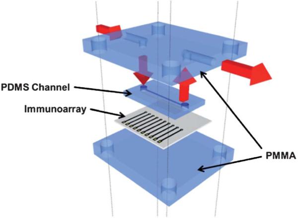
Fitting the 8-electrode immunoarray into the microfluidic device. The array is sandwiched between two layers of PMMA and one layer of PDMS acting as microfluidic channel above the sensor electrodes. The red arrows indicate the flow of buffer.
Atomic force microscopy (AFM) was done using a Digital Instruments Nanoscope IV scanning probe microscope, in tapping mode with symmetric tip high resolution Tapping Mode AFM probes (Veeco Metrology Inc., Model MPP-11100).
Preparation of gold CD-R
A gold CD-R consists of four layers: a rigid polycarbonate, an organic dye, a gold metallic layer and an outer protective layer. The CD-R was immersed in concentrated nitric acid for 1 min to remove the protective layer, and then cut using scissors into desired shapes and sizes. Cutting the CD-R before removing the protective layer damaged the underlying gold layers.37 The nitric acid treated CD-R was then washed with water, dried under nitrogen, and used immediately for array fabrication.
Fabrication of electrode arrays
A mask was designed using the graphic design software package Canvas 11 on a 1: 1 scale (Fig. S1, ESI†). It was then printed onto waxed paper (obtained from the backing of Avery labels) using the HP laserjet at 1200 dots per inch (dpi). The mask was then cut and placed onto a cut piece of gold CD-R processed as above. The CD-R piece and toner mask were then sandwiched within the thermal press at 120 −C for 110 s (Scheme 1). The contact area and working electrode were manually covered by inking with a Sharpie ® permanent marker before etching.38,39 The ink containing N-butanol, N-propanol, and 4-hydroxy-4-methyl-2-pentanone in the Sharpie ® provides an excellent etch resist to the gold etchant to protect the gold film.39 A gold etchant solution containing 0.1 M potassium thiosulfate, 1 M potassium hydroxide, 0.01 M potassium ferricyanide, and 0.001 M potassium ferrocyanide was used to remove the unprotected gold.40 The gold on the surface is first oxidized by ferricyanide. Thio-sulfate then binds to the gold ions and solubilizes them. The solution is basic to prevent degradation of thiosulfate. Finally, the arrays were washed with ethanol, then water. This exposes the contact pads and sensor electrodes as shown in Scheme 1(e). After washing, the arrays were dried under nitrogen. Then, a second layer of laserjet toner was heat transferred from wax paper onto the arrays to define the surface area of the electrodes and create hydrophobic microwells around each electrode (Fig. 2b and S2, ESI†).
Scheme 1.

Steps in the fabrication of gold arrays from commercial gold CD-Rs. (a) Remove the protective layer of the CD-R to expose the gold film; (b) print the array pattern on wax paper using a laserjet printer and transfer onto the gold surface by applying heat and pressure, contacts are the squares at the bottom of each chip, electrodes are the circles in the middle of chip; (c) use a Sharpie ® pen to cover contact pads and electrodes; (d) remove unprotected gold in etchant solution; (e) wash with ethanol/water to expose contact pads and electrodes; (f) transfer second layer of toner by heat to form wells.
Fig. 2.
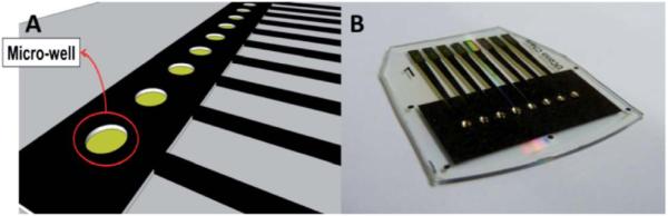
(a) Computer generated design of the gold CD-R array showing microwells around electrodes. (b) Completed array of 8 electrodes with individual microwells containing 1 μL aqueous droplets.
Preparation of immunosensors for Interleukin-6
The array was cleaned in 0.18 M sulfuric acid while applying 10 cycles of potential sweeps between 1.5 V and 0.1 V, then rinsed with ethanol and water before immersing into 4 mM mercapto-propionic acid (MPA) in 20% ethanol for 46 h under N2 to form a self-assembled monolayer (SAM). The outward facing surface carboxylic groups of MPA were activated using freshly prepared 400 mM EDC and 100 mM NHSS. The array was rinsed with water after 10 min and anti-human IL-6 capture antibody (Ab1) was attached by amidization between the activated carboxylic groups of SAM and the Ab1 using optimized conditions of 1.0 μL of 100 μg mL −1 Ab1 per sensor electrode (8 μL per array) for 3 h. The array was washed by gently dipping into 0.05% Tween-20 in PBS and then PBS for 3 times each. Each electrode on the arrays was then incubated with 1.0 μL of 2% BSA for 10 min, followed by the same washing steps. For standardization, 1.0 μL of the respective concentration of human IL-6 antigen (Ag) in 5000-fold serially diluted calf serum in pH 7.4 PBS was dropped onto each electrode and incubated for 1 h. This dilution was used because it corresponds to that required for bringing clinical samples into the linear range of the immunoassay. After washing again in 0.05% Tween-20 in PBS, then PBS, each electrode was incubated with 1.0 μL of 9 μg mL −1 biotinylated anti-human IL-6 secondary antibody (Ab2) for 1 h. Again, arrays were washed and incubated with 1.0 μL of 1: 500 diluted streptavidin poly-HRP in PBS for 1 h. The dilution of streptavidin poly-HRP was optimized to achieve the best signal to noise ratio. All incubations were done at room temperature in high humidity chambers unless otherwise noted.
After a final wash in 0.05% Tween-20 in PBS, then PBS, the immunoarray was placed in the microfluidic device for electro-chemical analysis. A mixture of pH 7.4 PBS purged with nitrogen for 30 min and 1 mM hydroquinone (HQ) was pumped through the channel using the syringe pump at 100 μL min −1. Detection was done using amperometry at −0.3 V vs. Ag/AgCl by injecting a deoxygenated mixture of 100 μM H2O2 and 1 mM HQ mediator in PBS using the sample loop.
Results
Characterization of electrode arrays
Tapping-mode atomic force microscopy (AFM) images (Fig. 3a) revealed grooves in the gold CD surface41 that were found on the sensor electrodes. After the IL-6 capture antibodies were covalently linked onto the SAM layer on the gold, AFM images showed a distribution of globular shaped hills which were more apparent at higher resolution (Fig. 3b and c). These globular shapes are generally characteristic of high antibody surface coverage.42
Fig. 3.

Tapping mode AFM images of (a) exposed bare gold CD-R surface, (b) anti-IL-6 capture antibody attached to the gold CD-R surface. (c) Same as (b) at 10-fold higher resolution showing globular structures characteristic of attached antibodies.
Cyclic voltammetry (CV) of the bare array in 0.18 M sulfuric acid vs. Ag/AgCl reference electrode in the microfluidic device between −0.1 V and +1.5 V at 100 mV s −1 (Fig. S5, ESI†) showed similar peaks to those from bulk gold. Peaks were found for formation of gold oxide at +1.2 V and reduction of the oxide to bulk gold at −0.9 V.43
The design pattern was set up to print eight disk electrodes with a diameter of 850 μm. During thermal transfer onto the gold CDs, the toner spreads as expected and reduced the effective geometric area of the electrodes. After thermal transfer, the diameter of each electrode was 800 ± 25 μm estimated using fiducial camera images, and the surface area was 0.50 0.03 mm2. The dry resistance of gold arrays from contract pads to working electrodes was 17.6 0.2 ohms.
To assess reproducibility of the electrochemically addressable area in the absence of immunosensing, cyclic voltammetry was done on all electrodes on the array simultaneously in an unstirred solution of 5 mM ruthenium hexamine chloride [Ru (NH3)6]–Cl3 and 0.1 M sodium trifluoroacetate (NaTFA) after cleaning the gold surface by potential sweeping in sulfuric acid. Using the Randles–Sevcik equation and the known diffusion coefficient of ruthenium hexamine chloride,44 the surface area was estimated to be 0.42 ± 0.07 mm2, which is ~85% of the estimated geometric area with a relative standard deviation of <2% between electrodes. Amperometric signals were also measured on all electrodes in the microfluidic device after injection of 100 μM [Ru(NH3)6]-Cl3 solution. All 8 electrodes of the array gave similar peak currents (Fig. 4b), with an average of 12.2 ± 0.5 nA (RSD < 5%), demonstrating the absence of cross-talk between neighboring electrodes during microfluidic flow conditions.
Fig. 4.
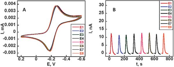
Array reproducibility: (a) CVs at 50 mV s −1 on 8-electrodes of a gold CD-R array in 5 mM ([Ru(NH3)6]-Cl3) in aqueous 0.1 M sodium trifluoroacetate (NaTFA). (b) Amperometric response of the 8-electrode array in the microfluidic device to injection of 100 μL of 100 μM ([Ru (NH3)6]-Cl3) at 100 μL min −1.
Immunoassay development
All sensor arrays were first cleaned by cycling in sulfuric acid to remove gold oxide from the surface. Then a SAM coating was made by immersing the sensor arrays into MPA solution. Immunoarrays for interleukin-6 (IL-6) were developed by covalently binding anti-human IL-6 capture antibody onto the SAM layers on each of the gold sensor surfaces. A single concentration of IL-6 in diluted serum was used per array and the amount used per electrode was 1.0 μL (8 μL per array). After full development of the assay, the gold sensor array was placed into the microfluidic device (Fig. 1). A mixture of 1 mM hydroquinone mediator and 100 μM hydrogen peroxide was then injected into the microfluidic device via the 100 μL sample loop to develop the amperometric response. Flow rates were optimized in the microfluidic device by varying flow rates of the injections between 50 and 250 μL min −1 to obtain the highest signal to noise ratio as previously described.8 Fresh chips were used for measuring each standard concentration.
Injections of the peroxide/mediator mixture produced low noise current peaks due to the conversion of HRP by peroxide to ferryloxy HRP, whose reduction is mediated by hydroquinone.33 Control experiments included the full immunoassay procedure without IL-6. The control response reflects the sum of residual non-specific binding and direct reduction of hydrogen peroxide. Representative amperometric responses are shown in Fig. 5a for a series of concentrations of IL-6 in 5000-fold diluted calf serum in PBS varying from 10 to 1280 fg mL −1. The high dilution factor was chosen to bring clinically relevant IL-6 concentrations into the linear range of the sensor. The DL for IL-6 as 3 times the average SD above the control was 10 fg mL −1.
Fig. 5.
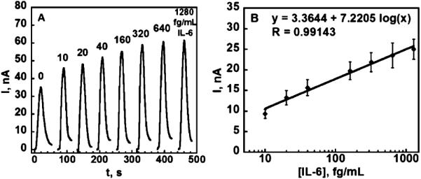
Amperometric data for immunoarray chips after exposure to diluted serum containing IL-6 and HRP-labeled secondary antibody: (a) responses for IL-6 in the microfluidic device at 0.3 V developed by injecting 100 μL 1 mM hydroquinone +100 μM H2O2. (b) Calibration plot for IL-6 standards in diluted serum after the subtraction of control (n = 6).
Discussion
The above results show that non-lithographic fabrication from gold compact discs offers a simple and inexpensive route to reproducible and ultrasensitive amperometric arrays for the detection of protein biomarkers. A single array as described herein costs less than US $0.20 in materials to produce, and requires no specialized equipment. One of the major advantages of this technique is the ease of modification of the printed pattern, which is customizable for virtually any application. This allows rapid development of prototypes using common graphical software such as PowerPoint ®.
The spreading of reagents and sample solution is a major concern during sandwich immunoassays on electrochemical arrays. It can cause cross-contamination, decrease precision, and increase amounts of reagents needed. Solution spreading was eliminated in the present arrays by creating hydrophobic microwells around the sensor electrodes by placing a second layer of toner around them. The hydrophobic toner creates a barrier around individual sensors allowing the confinement of ~ 1 μL of aqueous solution above each sensor element (Fig. 2b and S2, ESI†). The transference of a second layer of toner onto the arrays also eliminated human error from manually inking with Sharpie pens and improved the reproducibility of sensor area to <2% from sensor to sensor. The well-defined and nearly reversible peaks of the ruthenium redox couple in the cyclic voltammogram (Fig. 4a) with a peak separation of ~80 mV further indicate that the arrays are suitable for a range of electrochemical measurement applications. The similarities in amperometric peaks on these arrays under flowing conditions demonstrated that the electrodes on the array (Fig. 4b) produced equivalent electrochemical response with minimal cross-talk.
Immunosensing application
IL-6 is an over-expressed protein found in the blood of patients with oral, lung, colorectal and prostate cancers as well as inflammation.45-48 Serum IL-6 levels of cancer patients can elevate to thousands of pg mL −1 compared to normal levels of <6 pg mL −1. The low concentrations of IL-6 in normal serum make it especially challenging for immunoassays. Thus, amplification techniques must be used to improve the DL for IL-6 protein. In previous work, we developed single electrode immunosensors utilizing carbon nanotube forests or 5 nm gold nanoparticles to increase surface area allowing more capture antibodies to be attached.8,19,30-32 Combined with particles labeled with 200 000 HRPs and antibodies attached, these systems enhanced the detection limit of IL-6 in serum into the sub-pg mL −1 range.8
In this work, we chose an alternative, rapid amplification strategy that substitutes streptavidin poly-HRP for the more commonly used streptavidin HRP to improve sensitivity and limit of detection. This streptavidin poly-HRP featured polymers of multiple HRP molecules conjugated to streptavidin, which bind to the biotinylated secondary antibody. This supramolecular enzyme complex contains increased molar ratio of HRP enzyme labels per biotin-streptavidin binding event49,50 while retaining the functionality of the strong binding couple as shown in Scheme 2. This amplification strategy is implemented simply by replacing the streptavidin-HRP with streptavidin poly-HRP during the last step of incubation for attachment to the detection antibody, which is attached to the previously captured analyte protein. Using the procedures for amperometric detection in the microfluidic device described above, peak currents increased from 10 fg mL −1 to 1300 fg mL −1 for IL-6 concentration in diluted serum with DL 10 fg mL −1 (Fig. 5b). This ultra-low DL is ~200 times lower than our previously reported immunosensors for IL-6 with 14-16 HRP labels on single-electrode immunosensors in conventional three electrodes cells and ~30-fold lower than the DL in our alternative microfluidic immunoassay system employing more expensive screen printed arrays and magnetic particles with 200 000 HRPs, while offering similar sensitivity. Similar to this alternative device, good selectivity for IL-6 is indicated by its successful detection in the presence of the thousands of other proteins present in serum. The use of microfluidics decreases the amount of reagents and the time required for detection by roughly 20-fold compared to our previous systems.31,32 Lastly, microfluidics provided excellent control of mass transport that improved the signal/noise ratio while making the detection system more portable.
Scheme 2.
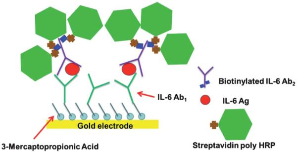
Schematic of an amplification strategy using streptavidin poly-HRP. The streptavidin poly-HRP is attached to the biotinylated anti-human IL-6 detection antibody.
Conclusions
The above results demonstrate that integration of immunoarrays easily fabricated from gold CD-Rs into a microfluidic device has excellent potential as a cheap, disposable chip-based diagnostic tool for early cancer detection and monitoring. The 8-electrode arrays should be readily adaptable to multiple protein detection and further automation, goals that we are presently pursuing.
The use of a simple amplification strategy with the gold arrays in a microfluidic system enabled the immunosensing of IL-6 in diluted serum with DL 10 fg mL −1, well below the normal patient level. This very low detection limit allows extensive dilution of samples to help minimize non-specific binding of potentially interfering biomolecules in serum, and may also be useful in tests for cancer recurrence.
Supplementary Material
Acknowledgements
This work was supported by NIH through grants R01ES013557 from the National Institute of Environmental Health Sciences and R01EB014586 from the National Institute of Biomedical Imaging and Bioengineering.
Footnotes
Electronic supplementary information (ESI) available. See DOI: 10.1039/c1lc20833k
Notes and references
- 1.Rusling JF, Kumar CV, Gutkind JS, Patel V. Analyst. 2010;135:2496–2511. doi: 10.1039/c0an00204f. and references therein. [DOI] [PMC free article] [PubMed] [Google Scholar]
- 2.Bakker E. Anal. Chem. 2004;76:3285–3298. doi: 10.1021/ac049580z. [DOI] [PubMed] [Google Scholar]
- 3.Wang J. Analyst. 2005;130:421–426. doi: 10.1039/b414248a. [DOI] [PubMed] [Google Scholar]
- 4.Wilson MS, Nie W. Anal. Chem. 2006;78:2507–2513. doi: 10.1021/ac0518452. [DOI] [PubMed] [Google Scholar]
- 5.Wilson MS, Nie W. Anal. Chem. 2006;78:6467–6483. doi: 10.1021/ac0518452. [DOI] [PubMed] [Google Scholar]
- 6.Wei F, Liao W, Xu Z, Yang Y, Wong DT, Ho C-M. Small. 2009;5:1784–1790. doi: 10.1002/smll.200900369. [DOI] [PMC free article] [PubMed] [Google Scholar]
- 7.Wei F, Patel P, Liao W, Chaudhry K, Zhang L, Arellano-Garcia M, Hu S, Elashoff D, Zhou H, Shukla S, Shah F, Ho C-M, Wong DT. Clin. Cancer Res. 2009;15:4446–4452. doi: 10.1158/1078-0432.CCR-09-0050. [DOI] [PMC free article] [PubMed] [Google Scholar]
- 8.Chikkaveeraiah BV, Mani V, Patel V, Gutkind JS, Rusling JF. Biosens. Bioelectron. 2011;26:4477–4483. doi: 10.1016/j.bios.2011.05.005. [DOI] [PMC free article] [PubMed] [Google Scholar]
- 9.Dong H, Li CM, Zhang YF, Cao XD, Gan Y. Lab Chip. 2007;7:1752–1758. doi: 10.1039/b712394a. [DOI] [PubMed] [Google Scholar]
- 10.Fragoso A, Latta D, Laboria N, von Germar F, Hansen-Hagge TE, Kemmer W, Gartner C, Klemm R, Drese KS, O’Sullivna CK. Lab Chip. 2011;11:625–631. doi: 10.1039/c0lc00398k. [DOI] [PubMed] [Google Scholar]
- 11.Qiang L, Vaddiraju S, Rusling JF, Papadimitrakopoulos F. Biosens. Bioelectron. 2010;26:682–688. doi: 10.1016/j.bios.2010.06.064. [DOI] [PMC free article] [PubMed] [Google Scholar]
- 12.Huang XJ, O’Mahony AM, Compton RG. Small. 2009;5:776–788. doi: 10.1002/smll.200801593. [DOI] [PubMed] [Google Scholar]
- 13.Nagale MP, Fritsch I. Anal. Chem. 1998;70:2902–2907. [Google Scholar]
- 14.Ordeig O, Godino N, Campo J, Munoz FX, Nikoljeff F, Nyholm L. Anal. Chem. 2008;80:3622–3632. doi: 10.1021/ac702570p. [DOI] [PubMed] [Google Scholar]
- 15.Metters JP, Kadara RO, Banks CE. Analyst. 2011;136:1067–1076. doi: 10.1039/c0an00894j. [DOI] [PubMed] [Google Scholar]
- 16.Renedo OD, Alonso-Lomillo MA, Arcos MJ. Martinez, Talanta. 2007;73:202–219. doi: 10.1016/j.talanta.2007.03.050. [DOI] [PubMed] [Google Scholar]
- 17.Schuler T, Asmus T, Fritzsche W, Moller R. Biosens. Bioelectron. 2009;24:2077–2084. doi: 10.1016/j.bios.2008.10.028. [DOI] [PubMed] [Google Scholar]
- 18.Escamila-Gomez V, Campuzano S, Pedrero M, Pingarron JM. Biosens. Bioelectron. 2009;11:3365–3371. doi: 10.1016/j.bios.2009.04.047. [DOI] [PubMed] [Google Scholar]
- 19.Jensen GC, Krause CE, Sotzing GA, Rusling JF. Phys. Chem. Chem. Phys. 2011;13:4888–4894. doi: 10.1039/c0cp01755h. [DOI] [PMC free article] [PubMed] [Google Scholar]
- 20.Zhao N, Chiesa M, Sirringhaus H. J. Appl. Phys. 2007;101:064513. [Google Scholar]
- 21.Ko SH, Pan H, Grigoropoulous CP, Luscombe CK, Frechet JMJ, Poulikakos D. Nanotechnology. 2007;18:345202. [Google Scholar]
- 22.Erickson D, Li D. Anal. Chim. Acta. 2004;507:11–26. [Google Scholar]
- 23.Whitesides GM. Nature. 2006;442:368–373. doi: 10.1038/nature05058. [DOI] [PubMed] [Google Scholar]
- 24.Ng HC, Uddayasankar U, Wheeler AR. Anal. Bioanal. Chem. 2010;397:991–1007. doi: 10.1007/s00216-010-3678-8. [DOI] [PubMed] [Google Scholar]
- 25.Wang J. Biosens. Bioelectron. 2006;21:1887–1892. doi: 10.1016/j.bios.2005.10.027. [DOI] [PubMed] [Google Scholar]
- 26.Giljohan DA, Mirkin CA. Nature. 2009;426:461–464. doi: 10.1038/nature08605. [DOI] [PMC free article] [PubMed] [Google Scholar]
- 27.Kulasingam V, Diamandis EP. Nat. Clin. Pract. Oncol. 2008;5:588–599. doi: 10.1038/ncponc1187. [DOI] [PubMed] [Google Scholar]
- 28.Hanash SM, Baik CS, Kallioniemi O. Nat. Rev. Clin. Oncol. 2011;8:142–150. doi: 10.1038/nrclinonc.2010.220. [DOI] [PubMed] [Google Scholar]
- 29.Yu X, Munge B, Patel V, Jensen G, Bhirde A, Gong JD, Kim SN, Gillespie J, Gutkind JS, Papadimitrakepoulos F, Rusling JF. J. Am. Chem. Soc. 2006;128:11199–11205. doi: 10.1021/ja062117e. [DOI] [PMC free article] [PubMed] [Google Scholar]
- 30.Mani V, Chikkaveeraiah BV, Patel V, Gutkind JS, Rusling JF. ACS Nano. 2009;3:585–594. doi: 10.1021/nn800863w. [DOI] [PMC free article] [PubMed] [Google Scholar]
- 31.Munge BS, Krause CE, Malhotra R, Patel V, Gutkind JS, Rusling JF. Electrochem. Commun. 2009;11:1009–1012. doi: 10.1016/j.elecom.2009.02.044. [DOI] [PMC free article] [PubMed] [Google Scholar]
- 32.Malhotra R, Patel V, Vaque JP, Gutkind JS, Rusling JF. Anal. Chem. 2010;82:3118–3123. doi: 10.1021/ac902802b. [DOI] [PMC free article] [PubMed] [Google Scholar]
- 33.Chikkaveeraih BV, Bhirde A, Malhotra R, Patel V, Gutkind JS, Rusling JF. Anal. Chem. 2009;81:9129–9134. doi: 10.1021/ac9018022. [DOI] [PMC free article] [PubMed] [Google Scholar]
- 34.Angnes L, Richter EM, Augelli MA, Kume GH. Anal. Chem. 2000;72:5503–5506. doi: 10.1021/ac000437p. [DOI] [PubMed] [Google Scholar]
- 35.Cho HJ, Parameswaran M, Yu HZ. Sens. Actuators, B. 2007;123:749–756. [Google Scholar]
- 36.Li YC, Li CH, Parameswaran M, Yu HZ. Anal. Chem. 2008;80:8814–8821. doi: 10.1021/ac801420h. [DOI] [PubMed] [Google Scholar]
- 37.Daniel D, Gutz IGR. Electrochem. Commun. 2003;5:782–786. [Google Scholar]
- 38.Ferreira HEA, Daniel D, Bertotti M, Richter EM. J. Braz. Chem. Soc. 2008;19:1538–1545. [Google Scholar]
- 39.Manica DP, Ewing AG. Electrophoresis. 2002;23:3735–3743. doi: 10.1002/1522-2683(200211)23:21<3735::AID-ELPS3735>3.0.CO;2-7. [DOI] [PubMed] [Google Scholar]
- 40.Xia Y, Zhao X, Kim E, Whitesides GM. Chem. Mater. 1995:2332–2337. [Google Scholar]
- 41.Yu HZ. Chem. Commun. 2004:2633–2636. doi: 10.1039/b412784f. [DOI] [PubMed] [Google Scholar]
- 42.Malhotra R, Papadimitrakopoulos F, Rusling JF. Langmuir. 2010;26:15050–15056. doi: 10.1021/la102306z. [DOI] [PMC free article] [PubMed] [Google Scholar]
- 43.Cadle SH, Bruckenstein S. Anal. Chem. 1974;46:16–20. [Google Scholar]
- 44.Bard AJ, Faulkner LR. Electrochemical Methods: Fundamentals and Application. 2nd edn John Wiley & Sons; New York: 2001. [Google Scholar]
- 45.Zhang GJ, Adachi I. Anticancer Res. 1999;19:1427–1432. [PubMed] [Google Scholar]
- 46.Wei LH, Kuo ML, Chen CA, Chou CH, Cheng WF, Chang MC, Su JL, Hsieh CY. Oncogene. 2001;20:5799–5809. doi: 10.1038/sj.onc.1204733. [DOI] [PubMed] [Google Scholar]
- 47.Chung YC, Chaen YL, Hsu CP. Anticancer Res. 2006;26:3905–3911. [PubMed] [Google Scholar]
- 48.Riedel F, Zaiss I, Herzog D, Gotte K, Naim R, Horman K. Anticancer Res. 2005;25:2761–2766. [PubMed] [Google Scholar]
- 49.Thermo Scientific website. http://www.piercenet.com/
- 50.Senova Immunoassay Systems website. http://senova.de/
Associated Data
This section collects any data citations, data availability statements, or supplementary materials included in this article.