Abstract
Background
High Intensity Focused Ultrasound (HIFU) has been introduced for treatment of cardiac arrhythmias, because it offers the ability to create rapid tissue modification in confined volumes without directly contacting the myocardium. In spite of the benefits of HIFU, a number of limitations have been reported, which hindered its clinical adoption.
Methods and Results
In this study, we used a multimodal approach to evaluate thermal and non-thermal effects of HIFU in cardiac ablation. We designed a computer-controlled system capable of simultaneous fluorescence mapping and HIFU ablation. Using this system, linear lesions were created in isolated rabbit atria (n = 6) and point lesions were created in the ventricles of whole-heart (n = 6) preparations by applying HIFU at clinical doses (4–16W). Additionally, we evaluate the gap size in ablation lines necessary for conduction in atrial preparations (n = 4). The voltage sensitive dye di-4-ANEPPS was used to assess functional damage produced by HIFU. Optical coherence tomography and general histology were used to evaluate lesion extent. Conduction block was achieved in 1 (17%) of 6 atrial preparations with a single ablation line. Following 10 minutes of rest, 0 (0%) of 6 atrial preparations demonstrated sustained conduction block from a single ablation line. Tissue displacement of 1–3mm was observed during HIFU application due to acoustic radiation force along the lesion line. Additionally, excessive acoustic pressure and high temperature from HIFU generated cavitation causing macroscopic tissue damage. A minimum gap size of 1.5mm was found to conduct electrical activity.
Conclusions
This study identified three potential mechanisms responsible for the failure of HIFU ablation in cardiac tissues. Both acoustic radiation force and acoustic cavitation in conjunction with inconsistent thermal deposition can increase the risk of lesion discontinuity and result in gap sizes that promote ablation failure.
Keywords: cardiac arrhythmias, ablation, high intensity focused ultrasound, acoustic radiation force, cavitation, thermal effect
Introduction
High Intensity Focused Ultrasound (HIFU) has become an attractive option for treatment of atrial fibrillation (AF) and other arrhythmias.1–7 HIFU can create rapid tissue modification in confined tissue volumes (as small as 20mm3) without directly contacting the myocardium.2,8 Furthermore, HIFU has a unique capability to induce intra-mural lesions at various depths without affecting intervening tissues.2,8 However, HIFU has limitations, which stem from incomplete understanding of physiological mechanisms of HIFU energy deposition in the heart. In recent clinical trials using St. Jude’s Epicor™ HIFU ablation system and ProRhythm’s HIFU Balloon Ablation Catheter, several complications were identified, including atrial-esophageal fistula, pulmonary embolism, and phrenic nerve damage.8–11
When discussing the benefits and drawbacks of HIFU as a tool for cardiac ablation, it is important to note a few basic principles regarding ultrasound. Ultrasound is a mechanical wave involving periodic changes of local pressure and density at frequencies above 20kHz.12 Propagation and scattering of ultrasonic waves in biological tissue have been used for both diagnostic imaging and therapeutic applications. Unlike diagnostic ultrasound, which generally operates in a higher frequency band (e.g. 5–30MHz), therapeutic ultrasound, such as HIFU systems, often operates at lower frequencies (e.g. 0.5–5MHz) and uses higher acoustic energy to induce irreversible tissue changes.12 Typical HIFU transducers are designed with a strong geometric or electronic focus to concentrate acoustic energy in a cigar-shaped profile with its length and width dependent on the transducer F-number and center frequency.13
HIFU can produce effects in tissue through three primary mechanisms: mechanical, thermal, and cavitation (which is a special form of mechanical effects).12–15 When exposed to an acoustic field, tissue is subjected to the acoustic radiation force or acoustic radiation pressure associated with the gradient of the acoustic energy distribution in a medium.15 Temperature elevation during ultrasound application is dependent on a combination of both tissue properties, including thermal absorption coefficient and perfusion rate, as well as ultrasonic parameters such as acoustic intensity (or acoustic pressure amplitude) and exposure duration.14,15 HIFU ablation relies on achieving a thermal dose above a specific threshold to create coagulative necrosis, described by the critical cumulative equivalent minutes at 43°C (CEM43).16,17 In addition to thermal effects, non-thermal effects, such as acoustic cavitation, can also occur during ablation as gas is extracted from tissue due to high acoustic pressures and high temperature, forming a gas bubble.12,15 Gas bubbles formed during HIFU exposures are highly dynamic and often collapse violently, generating local tissue fragmentation and cavity.12,15 Gas bubble formation and pulsation also have the potential to increase localized tissue heating, resulting in asymmetric lesion formation.13
In this study, we investigated biological effects of HIFU during the creation of focal and linear lesions in isolated right atrial (RA) and whole-heart rabbit preparations. Using a combination of optical mapping, optical coherence tomography (OCT), and histology, we evaluated the thermal and non-thermal effects of HIFU on the creation of focal and linear lesions in rabbit cardiac tissue specimens.
Methods
Optical Mapping and Ultrasound Ablation System
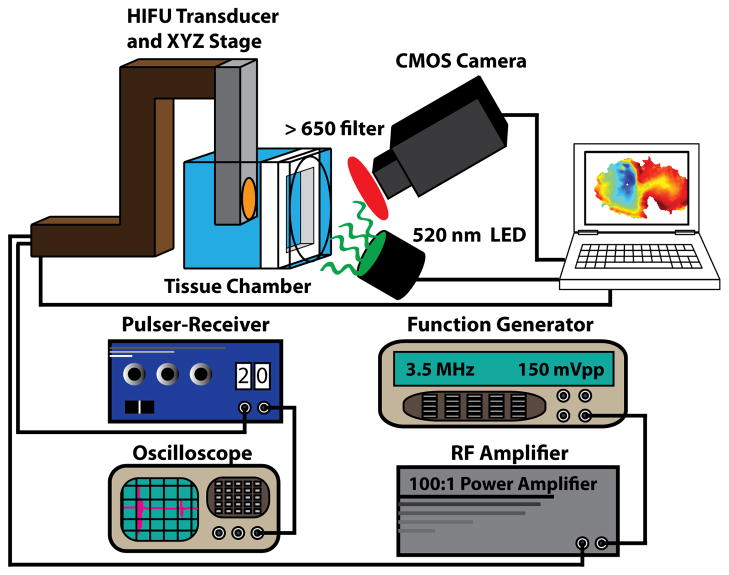
Experiments were conducted using the experimental system depicted in figure 1. This system allows for simultaneous ablation with a custom HIFU system and fluorescence imaging using voltage sensitive dye. Optical mapping was performed with a 100×100 pixel CMOS camera (MiCam Ultima-L, SciMedia USA, Costa Mesa, CA) focused on the endocardial surface of the preparation. All fluorescence data were acquired at 1000 frames per second (FPS). Two 520nm (±45nm) light emitting diodes (LEDs) were used for fluorescence excitation. Emission fluorescence was long-passed filtered (>650nm). Ablation was performed using a 3.5MHz HIFU transducer (SU-102, Sonic Concepts, Bothell, WA) connected to a 50W power amplifier (Amplifier Research, Souderton, PA) and a function generator (Agilent, Santa Clara, CA). The HIFU transducer was calibrated in a water tank with a fiber optic hydrophone to measure the peak positive pressure and the spatial-peak pulse-average intensity (ISPPA). The focal distance of the transducer was found to be 57mm. The 3-dB focal dimension of the HIFU transducer was measured to be 0.6mm (radial) × 7mm (axial). A pulser-receiver (Olympus Corp., Waltham, MA) and an oscilloscope were used to guide the placement of the HIFU focus at the tissue preparation. To ensure precise ablations, the HIFU transducer was attached to a XYZ computer-controlled stage (Zaber Technologies, Vancouver, BC) and controlled with a custom user-interface designed in MATLAB (Mathworks, Natick, MA). The minimum step-size of the XYZ stage is 2μm.
Figure 1.
Combined HIFU-optical mapping system. This system includes a custom ablation system consisting of a 3.5MHz HIFU transducer and XYZ stage. A pulser-receiver and oscilloscope are used to focus HIFU energy on the tissue of interest and a function generator and RF amplifier are used to drive the transducer. The optical mapping system includes a 100×100 CMOS camera.
Tissue preparations
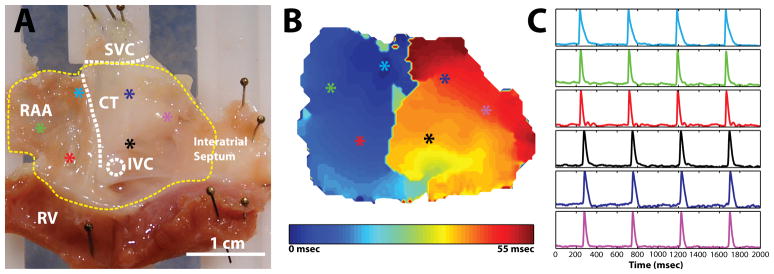
Two separate tissue preparations were used during HIFU evaluation in this study: Langendorff-perfused whole-heart preparations (n = 6) and isolated RA preparations (n = 10). All studies involving the use of animals were approved by the Institutional Animal Studies Care and Use Committee of Washington University in St. Louis. New Zealand white rabbits (n = 16, 4–5 mos. old, 3–4kg) were heparinized (1000 units) and anesthetized with pentobarbital (50mg/kg) intravenously. Following a midsternal incision, the heart was removed and placed onto a Langendorff apparatus, where it was retrogradedly perfused with oxygenated (95% O2, 5% CO2) Tyrode’s solution at 37°C. The heart was then cleaned of fat and pericardial tissue and stained with 50μL of 15-μM di-4-ANEPPS (Molecular Probes, Eugene, Oregon) over a period of 10 minutes. To create an isolated RA preparation, the intact heart was quickly dissected in a bath of room temperature Tyrode’s solution to create a preparation containing the right atrial appendage (RAA), the interatrial septum, and a thin strip (approximately 5mm) of right ventricle (see figure 2). Each preparation was pinned to a custom tissue frame and stretched approximately 3.5mm (10%) of the unloaded width and 2.5mm (10%) of the unloaded height. The preparation was then mounted vertically in a custom tissue chamber and superfused at 70mL/min with perfusate containing 10μM of the excitation-contraction uncoupler Blebbistatin (BB, Tocris Bioscience, Ellisville, MO) to reduce motion artifact during optical mapping experiments. A representative preparation with sinus rhythm optical action potentials (OAP) and conduction map are shown in figure 2.
Figure 2.
Experimental preparation. A: Endocardial view of right atrial preparation with important structures labeled. Colored asterisks indicate locations of representative optical signals. B: Activation map during sinus rhythm before ablation. C: Representative optical signals from colored asterisks. RAA: right atrial appendage; CT: crista terminalis; IVC: inferior vena cava; SVC: superior vena cava; RV: right ventricle.
Ablation Protocol
Three ablation protocols were used during experimentation to create (1) point lesions, (2) continuous linear lesions, and (3) continuous linear lesions with a gap in separate preparations. For creation of (1) point lesions, left and right ventricular myocardium was ablated at 973–1688 W/cm2 for 6 seconds in whole-heart preparations (n = 6) at 2 locations on the anterior and posterior surface. Ventricular tissue was used to evaluate non-transmural lesion profiles created by HIFU. For evaluation of transmural linear lesions, ablation was performed on isolate RA specimens (n = 10). Rabbit atrial tissue was selected for testing due to its thin width (2–3mm) relative to the focal width (8mm) of the HIFU transducer. The ratio of tissue thickness to focal width of the transducer ensures that the lesion created would be transmural—an important criteria to achieving conduction block. All linear ablations were performed at 1200W/cm2 (7MPa) with a step size of 0.25mm and ablation duration of 2 seconds to ensure point lesion overlap. Additionally, 5 repeated ablation passes with an axial step size of 0.25mm were employed to ensure transmural ablation of atrial tissue. To create (2) continuous linear lesions, a linear array of overlapping point lesions was created using the computer-controlled system in n = 6 preparations. First, a primary linear lesion (5–15mm) was created from the superior vena cava (SVC) toward the tricuspid annulus. Optical files were recorded every 2.5mm during ablation to validate lesion progression and completeness of the primary lesion. Next, a secondary linear lesion of 5–10mm was formed from the tricuspid annulus toward the inferior end of the primary lesion. Optical files were recorded after every 1mm to monitor progression of the ablation and connection to the primary lesion. Following completion of the continuous lesion line, tissue was allowed to rest for a minimum of 10 minutes to test sustained conduction block. To evaluate gap size capable of conduction block, (3) linear lesions containing gap sizes of 1mm, 2mm, 4mm, and 6mm were created in (n = 4) RA preparations. For this purpose, a primary linear lesion (5–10mm) was created from the superior vena cava (SVC) toward the tricuspid annulus and optical files were recorded each 2.5mm during ablation. Next, a secondary linear lesion was formed from the tricuspid annulus toward the inferior end of the primary lesion to leave the appropriate gap size. Tissue was paced at a cycle length (CL) of 250ms with a custom platinum bipolar electrode on either side of the lesion line to document conduction through the gap. All HIFU ablation was performed with the power generator set to output powers of 5–20W. Accounting for conversion efficiency of electrical to acoustic power (~80%), the acoustic power range is approximately 4–16W, which is in the range of clinical application.8,9
Optical Coherence Tomography (OCT) and Histology
Following ventricular ablation of whole-heart preparations, tissue preparations were placed in 3.7% formaldehyde diluted in phosphate buffered saline (Sigma-Aldrich, St. Louis, Missouri) overnight at 4°C. The following day, samples were transferred to a 20% sucrose solution and kept at 4°C for two days to dehydrate the tissue. A swept-source OCT system (Thor Labs, Newton, NJ) coupled to a microscope was used to create 3D volumes of specific lesions. The axial and lateral resolution of the system is approximately 9μm and 25μm (in water), respectively. Individual OCT images were averaged at most 6 times to decrease noise, depending on the tissue sample at the time of acquisition. OCT data were collected as 512×512×512 pixel volumes. All volume reconstructions were produced using Volocity software (Perkin Elmer, Waltham, MA). After OCT imaging, point lesions were extract from the ventricular walls, sectioned at 16μm, and stained with Masson’s trichrome stain.
Tetrazolium Staining
Immediately following experimentation on isolated RA preparations, tissues were photographed and stained with triphenyltetrazolium (TTC, Sigma Aldrich, St. Louis, MO) as described.18 Briefly, tetrazolium powder was diluted in a two-part phosphate buffer consisting of NaHPO4 (0.1M) and NaH2PO4 (0.1M). Phosphate buffer was then combined in a ratio of 77.4%/22.6% (% NaHPO4: % NaH2PO4) to make the final buffer solution. Finally, tetrazolium salts were added at 1% weight/volume (gm/ml). All tissue was incubated in the tetrazolium solution for 10–15 minutes at 37°C. Following staining, tissue was again photographed.
Data Analysis
All data analysis was performed using a custom MATLAB GUI (available from efimov.wustl.edu). All optical data were filtered using a 3×3 pixel spatial filter and 2–100Hz FIR bandpass filter and then normalized between 0 and unity. Activation times were defined as the maximum first derivative of the fluorescent signal, dF/dtmax, and activation maps were constructed from the activation times of each pixel on the preparation.
Results
Demonstration of Normal Conduction
Figure 2 demonstrates OAPS (figure 2c) and the conduction pattern (figure 2b) during sinus rhythm of an isolated RA preparation using our ablation-mapping system before the onset of ablation. The activation map and optical signals agree with previously published data for isolated RA preparations from a rabbit.19 Conduction propagates from the sinoatrial node (SAN) near the crista terminals (CT) across the pectinate muscle of the RAA, and finally excites the interatrial septum.
Demonstration of Continuous Linear Ablation
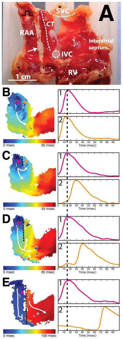
To test our ability to create a continuous line of conduction block, we followed the ablation protocol described previously. Continuous linear conduction block was achieved in 1 (17%) of 6 atrial preparations with a single ablation line (primary and secondary lesion) from the SVC to the tricuspid valve in the RAA. Figure 3 illustrates a typical experiment. Activation maps prior to ablation (figure 3b) and after ablation (figure 3c–e) are displayed. Separate panels illustrate the creation of linear lesions of increasing length: 5mm (3c), 15mm (3d), and 20mm (3e). Pink (1) and orange (2) tracings indicate OAPs from opposite sides of the ablation line and illustrate increasing conduction delay with progressive increase in the length of ablation line.
Figure 3.
Demonstration of continuous linear ablation. A: Endocardial view of right atrial preparation post TTC staining. Black square pulse represents pacing location. B: Activation map before HIFU ablation during pacing (CL = 250ms). Colored asterisks indicate location of optical signals. White arrow indicates ablation line. C: Activation map after creation of 5mm lesion with HIFU during pacing (CL = 250ms). D: Activation map after creation of 15mm lesion with HIFU during pacing (CL = 250ms). E: Activation map after creation of complete block with HIFU during pacing. As lesion length increases (C & D), larger conduction delay is observed between optical signals from pixel 1 (pink) and pixel 2 (orange). After entire conduction path has been ablated (E), sinus node drives electrical excitation on right side of preparation.
Prior to ablation, conduction propagates from the location of the pacing electrode in the RAA, around the inferior end of the CT, and toward the interatrial septum (figure 3b). After the creation of a 5mm lesion, conduction in the RAA was altered (3c). A delay of 15ms was observed between location 1 (pink) and location 2 (orange). This delay increased to 25ms as the lesion line was extended from 5mm to 15mm (3d). A clear line of conduction block along the path of HIFU ablation was observed in the activation map following connection of primary and secondary lesion lines (3e). After extending the lesion line through the full length of the preparation, the RAA became electrically isolated from the remainder of the atrial myocardium (figure 3e). Following isolation, we observed two activation rates in the preparation. On the left side of the lesion, the tissue activated with the pacing stimuli at CL=250ms. On the right side of the lesion, a spontaneous focus near the location of the SAN drove activation at a slower rate (CL=420ms).
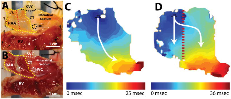
Following a minimum rest period of 10 minutes, 0 (0%) of 6 atrial preparations demonstrated sustained conduction block from a single ablation line. In an attempt to create sustained block, a minimum of 5 additional passes of HIFU energy were applied to the ablation line in axial steps of 0.25mm. Sustained conduction block was achieved in 1 (17%) of 6 atrial preparations with multiple applications of HIFU energy. When sustained conduction block was unachievable with multiple HIFU applications, multiple lesion lines (average number of lines = 2.0) were created adjacent to the original ablation line. Multiple adjacent lesion lines were successful in creating conduction block in 1 (20%) of 5 atrial preparations. Figure 4 demonstrates an example of a failed electrical isolation following both multiple HIFU applications and multiple adjacent lesion lines. Figure 4c depicts normal electrical propagation from the pacing electrode (CL = 250ms) prior to ablation. Following ablation with multiple applications of HIFU and 2 adjacent lesion lines (figure 4d), conduction occurs through a gap in the lesion line. Post-experimental TTC staining demonstrates a 3mm-wide transmural region of necrotic tissue (figure 4b) and a small strip of viable tissue (white arrow) between adjacent lesion lines (figure 4b). However, the exact location and size of the gap was difficult to determine due to the increased damage caused by additional ablation attempts and multiple lesion lines.
Figure 4.
Discontinuous linear lesion. A: Endocardial view of isolated right atrial preparation with important structures labelled. Red dashed line indicates ablation line. Yellow outline indicates optical field of view. Black square pulse represents pacing location. B: Endocardial view of right atrial preparation post TTC staining. White arrow indicates unabalated myocardium. C: Activation map before ablation. D: Activation map post ablation. Lesion line is not continuous. Small gap allows excitation to proceed through ablation line.
Effects of the Acoustic Radiation Force
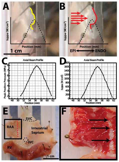
As a result of our failure to consistently produce sustained conduction block, we attempted to identify and document potential mechanisms for the failure of HIFU ablation. One potential mechanism of HIFU failure we observed in all of our preparations (16 (100%) of 16) is associated with the acoustic radiation force.15 To document the phenomenon of acoustic radiation force displacement during our ablation experiments, 3 representative preparations were filmed with a standard video camera from epicardial and transmural views. Figure 5 depicts a transmural view of the tissue before ablation (5a) and during ablation (5b). The axial beam profile measured by peak positive pressure and ISPPA are provided for reference in figures 5c and 5d, respectively. A plastic guard was pinned in front of the tissue for comparative purposes. During HIFU ablation, the tissue is displaced 1–3mm from its original location (figure 5a) toward the plastic guard (figure 5b). During this displacement, the target tissue (yellow trace in figure 5a) is moved from the peak ISPPA of the HIFU beam profile to a lower focal intensity (figure 5b). Correlation of real-time feedback of the computer-controlled stage, recorded video, and post experiment TTC staining indicate gaps in the lesion line at the locations of tissue displacement (indicated by arrows in figures 5e and 5f).
Figure 5.
Acoustic radiation force. A: Side profile of right atrial preparation before HIFU application. Yellow trace indicates profile of tissue surface. Black dashed trace indicates axial beam profile relative to tissue surface. B: Side profile of right atrial preparation during HIFU application. Red trace indicates displaced profile of tissue surface. Red arrows indicate direction of HIFU application. C: Peak positive pressure axial beam profile as a function of postion from transducer face. D: ISPPA axial beam profile as a function of position from transducer face. E: Right atrial preparation. Red line indicates ablation line. F: TTC staining post ablation. Arrows indicate gaps in ablation line.
Effects of Acoustic Cavitation
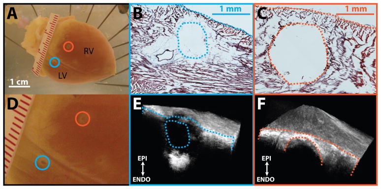
Another important side effect we identified with HIFU ablation is acoustic cavitation. Audible and visual signs of acoustic cavitation were observed during ablation in all preparations (16 (100%) of 16). Figure 6 demonstrates two examples (blue and orange) of acoustic cavitation on the posterior aspect of the heart during ventricular ablations. An audible pop was heard and release of tissue fragments into the perfusate was observed during the creation of both lesions. For the first ablation (blue), 1688 W/cm2 was directed toward the left ventricle (LV). Corresponding histological and OCT cross-sections through the center of the lesion are displayed in figures 6b and 6e. While coagulative necrosis was observed on the periphery of the lesion (figure 6b), a cavity at the lesion center is clearly visible. For the second ablation (orange), acoustic power was reduced to 973 W/cm2. Histological sections and OCT sections from the center of the lesion show a circular cavity devoid of tissue, which was obliterated by HIFU (figures 6c and 6f). Unlike the first lesion (blue), no coagulative necrosis was observed on the periphery of the lesion. This is a particularly severe complication of HIFU, since it irreversibly compromises tissue integrity.
Figure 6.
Acoustic cavitation. A: Posterior aspect of rabbit heart used for ablation. Blue and orange circles indicate location of lesions produced with HIFU. Blue lesion was created using 1688 W/cm2 of acoustic power and the orange lesion was created using 973 W/cm2 of acoustic power. B: Histological cross-section through center of blue lesion. C: Histological cross-section through center of orange lesion. D. Zoomed in image of posterior field of view. E: OCT volume of blue lesion. Exposed face represents cross-section corresponding to histology. F: OCT volume of orange lesion. Exposed face represents cross-section corresponding to histology. RV: right ventricle; LV: left ventricle.
Gap Size for Propagation through Continuous Lesion Lines
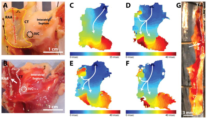
As documented, we observed discontinuous ablation lines and non-sustained conduction block during HIFU ablation with our system. Hence, we attempted to document the minimum gap size in a lesion line produced by HIFU that could sustain conduction. Figure 7 demonstrates optical mapping and histological results during the creation of a 2mm gap in a single atrial preparation. Prior to ablation (figure 7c), conduction was observed to propagate from the pacing electrode near the SVC and CT across the RAA, around the inferior portion of the CT, and toward the IVC. Figure 7d depicts conduction through a 6mm gap. Following ablation, conduction moves through the gap and bifurcates into two pathways: (1) a superior path toward the SVC and (2) an inferior path toward the atrioventricular (AV) groove. A similar conduction pattern was observed as gap size was decreased to 4mm (figure 7e) and 2mm (figure 7f). Following experimentation, the final gap size and lesion lines in the tissue were examined (figure 7g). Using a scalpel, the tissue was divided along with lesion line to expose a cross-sectional surface. The gap and ablation lines can be easily identified as red viable tissue and white ablated tissue, respectively. The final gap size in the tissue cross section was measure at 1.5mm. In other experiments, conduction through gap sizes as small as 0.5mm and 1mm were tested. However, due to the distributed nature of the HIFU beam profile, as well as other factors discussed previously, documentation of creation of smaller gaps proved difficult with our specific transducer.
Figure 7.
Conduction through gap. A. Endocardial view of isolated right atrial preparation with important structures labelled. Red dashed line indicates ablation line. Yellow outline indicates optical field of view. Black square pulse represents pacing location. B. Endocardial view of right atrial preparation post TTC staining. White arrow indicates ablation line. C. Activation map before ablation. D. Activation map after creation of 6mm gap. E. Activation map after creation of 4mm gap. F. Activation map after creation of 2mm gap. G. Cross section through center of lesion. White outlines indicate ablated tissue surface exposed with scalpel. Upper outline (1) indicates upper half of lesion line and lower outline (2) represents lower half of lesion line.
Discussion
To date, the majority of cardiac HIFU research has focused on the thermal effect of HIFU. Thermal dose is a critical component of ablation success, and prior research has been crucial in understanding the thermal capabilities of HIFU. Much like other ablation technologies, however, thermal deposition is not the only factor that occurs during HIFU application to tissue. In this study, we demonstrate three contributing factors to HIFU ablation: acoustic radiation force, acoustic cavitation, and discontinuous linear lesions.
Besides the primary thermal effect of HIFU, acoustic radiation force associated with HIFU application can displace tissue away from the HIFU focal zone, shifting the location of the intended ablation site away from the HIFU focus. During our experimental study, tissue displacement of 1–3mm was noted in all atrial (n = 10) and ventricular (n = 6) preparations. Displacement by acoustic radiation force was highly dependent on tissue properties. Thinner, more flexible tissue displayed greater displacement than thicker tissues. Depending on the amount of displacement in the focal zone, the targeted tissue site may not reach the necessary temperature during exposure to achieve irreversible cell death and gaps in lesion lines may occur (as shown in figure 4). Moreover, tissue could become temporarily stunned, but not fully ablated, allowing a conduction pathway to reestablish itself after a recovery period. In addition, unintended tissue sites can be inadvertently moved into the HIFU focus, causing unwanted damage. In recent clinical evaluations of St. Jude’s Epicor™ HIFU system, researchers reported temporal damage to the phrenic nerve and collateral damage to the esophagus during epicardial HIFU application.9,10 One explanation for these findings might be acoustic radiation force pushing the phrenic nerve into a focal zone conducive to nerve damage.
Another important and potentially dangerous phenomenon occurring during HIFU application is acoustic cavitation or gas body activity. Acoustic cavitation occurs due to the rapid creation and collapse of gas bubbles within tissue, which could result from high acoustic pressure or high temperature induced by HIFU.20 Much like “steam pops”21 produced during RF ablation, acoustic cavitation poses a substantial risk to patients. Cavitation could result in embolic events, tamponade, or cardiac perforation. Despite HIFU being used for many clinical applications, cavitation thresholds and effects are poorly understood.20 Researchers have shown that cavitation is dependent upon various tissue and transducer parameters such as convective cooling from nearby blood vessels, applied acoustic frequency, and tissue heterogeneities.20,22,23 In the current study, we present two examples of acoustic cavitation producing cavities in myocardium (figure 6). Additionally, we also observed several audible “pops” during the creation of linear lesions in all experiments—an observation not often mentioned by other researchers. One reason for missing this phenomenon in previous studies could be related to differences in the experimental design. We utilize oxygenated Tyrode’s solution to provide a physiologic environment for the heart, while other experimental evaluations of HIFU have been carried out in degassed saline.2,3,24 We feel Tyrode’s solution more accurately replicates in-vivo gas conditions, as well as decreases the risk of tissue ischemia. Increased gas levels in solution could lead to increased cavitational risk. Again, this might explain some of the reported side effects with the Epicor™ system on human subjects.9
Continuous, transmural lesion lines are vital to the success of ablation therapies.25,26 We attempted to investigate ablation success and importance of gap size to conduction block. Currently, controversy exists in reported gap sizes necessary for sustained acute conduction block. Melby et al. reports successful conduction in 93% of gaps between 1–3mm and conduction block for all gaps less than 1mm.26 More recently, Ranjan et al. describe median gap length of 4.15mm in canine ventricles as sufficient for conduction block.25 Our system provides a unique opportunity to create precise lesion lines and gaps in cardiac tissue. Using this system, we briefly evaluated the smallest viable gap that allows conduction. Similar to results from Melby et al., we observed conduction through gaps of 1–3mm in our experiments.26 These small gaps underscore the importance of controlling the effects of acoustic radiation force and cavitation. Disturbances that move tissue out of the HIFU focus or create irregular tissue damage can produce gaps on the order of 1mm that decrease ablation success and may increase the need for reablation procedures. Lesion discontinuity is not, however, completely based on non-thermal effects. Incomplete lesion lines can easily result from inconsistent thermal deposition due to the distributed nature of the HIFU beam profile.
Future HIFU research should focus on how to mitigate the effects of acoustic pressure and acoustic cavitation while promoting spatio-temporal thermal deposition. One way this might be achieved is through simultaneous (or real-time) monitoring of ablation. Dual-element transducers might be able to utilize a combination of diagnostic ultrasound and therapeutic ultrasound to ablate tissue and monitor lesion progress and tissue displacement. This approach would allow physicians to utilize the novel aspects of HIFU, while ensuring ablation success.
Limitations
We would like to acknowledge a few important limitations to our study. First, HIFU ablation was performed in an in-vitro setting on atrial tissue mechanically arrested using Blebbistatin. To compensate reduction of stiffness caused by Blebbistatin, atrial preparations were stretched as specified. In-vivo ablation on a beating heart with changing tissue tensions may potentially result in different HIFU-tissue interactions. Thus, reported mechanisms of failure observed in vitro may not entirely represent in-vivo ablation. Additionally, our isolated preparations are unlikely to replicate the effect of tissue surrounding the heart. The altered biomechanical environment may modulate the effects of acoustic cavitation and acoustic radiation force. Nevertheless, the complications observed in this study using simplified preparations have also been observed in more complex clinical evaluations of HIFU.
Conclusion
Three mechanisms were identified to interfere with the creation of linear conduction block during HIFU ablation: acoustic radiation force, cavitation, and discontinuity in linear lesions. If HIFU is to become a feasible option for cardiac ablation, the various mechanisms of tissue damage induced by HIFU need to be properly understood. Moreover, strategies need to be developed to mitigate the effects of acoustic radiation force and acoustic cavitation while promoting thermal deposition.
Acknowledgments
Funding Sources: NIH support (grant R01 EB008999) is gratefully acknowledged.
Footnotes
Conflict of Interest Disclosures: None
References
- 1.Aktas MK, Daubert JP, Hall B. Surgical atrial fibrillation ablation: a review of contemporary techniques and energy sources. Cardiol J. 2008;15:87–94. [PubMed] [Google Scholar]
- 2.Lee LA, Simon C, Bove EL, Mosca RS, Ebbini ES, Abrams GD, Ludomirsky A. High intensity focused ultrasound effect on cardiac tissues: potential for clinical application. Echocardiography. 2000;17:563–566. doi: 10.1046/j.1540-8175.2000.00563.x. [DOI] [PubMed] [Google Scholar]
- 3.He DS, Zimmer JE, Hynynen K, Marcus FI, Caruso AC, Lampe LF, Aguirre ML. Application of ultrasound energy for intracardiac ablation of arrhythmias. European Heart Journal. 1995;16:961–966. doi: 10.1093/oxfordjournals.eurheartj.a061031. [DOI] [PubMed] [Google Scholar]
- 4.Saliba W, Wilber D, Packer D, Marrouche N, Schweikert R, Pisano E, Shewchik J, Bash D, Fanelli R, Potenza D, Santarelli P, Tchou P, Natale A. Circumferential ultrasound ablation for pulmonary vein isolation: analysis of acute and chronic failures. Journal of Cardiovascular Electrophysiology. 2002;13:957–961. doi: 10.1046/j.1540-8167.2002.00957.x. [DOI] [PubMed] [Google Scholar]
- 5.Strickberger SA, Tokano T, Kluiwstra JU, Morady F, Cain C. Extracardiac ablation of the canine atrioventricular junction by use of high-intensity focused ultrasound. Circulation. 1999;100:203–208. doi: 10.1161/01.cir.100.2.203. [DOI] [PubMed] [Google Scholar]
- 6.Zimmer J, Hynynen K, He DS, Marcus F. The feasibility of using ultrasound for cardiac ablation. IEEE T Bio-Med Eng. 1995;42:891–897. doi: 10.1109/10.412655. [DOI] [PubMed] [Google Scholar]
- 7.Natale A, Pisano E, Shewchik J, Bash D, Fanelli R, Potenza D, Santarelli P, Schweikert R, White R, Saliba W, Kanagaratnam L, Tchou P, Lesh M. First human experience with pulmonary vein isolation using a through-the-balloon circumferential ultrasound ablation system for recurrent atrial fibrillation. Circulation. 2000;102:1879–1882. doi: 10.1161/01.cir.102.16.1879. [DOI] [PubMed] [Google Scholar]
- 8.Okumura Y, Kolasa MW, Johnson SB, Bunch TJ, Henz BD, O’Brien CJ, Miller DV, Packer DL. Mechanism of tissue heating during high intensity focused ultrasound pulmonary vein isolation: implications for atrial fibrillation ablation efficacy and phrenic nerve protection. Journal of Cardiovascular Electrophysiology. 2008;19:945–951. doi: 10.1111/j.1540-8167.2008.01162.x. [DOI] [PubMed] [Google Scholar]
- 9.Klinkenberg TJ, Ahmed S, Ten Hagen A, Wiesfeld ACP, Tan ES, Zijlstra F, Van Gelder IC. Feasibility and outcome of epicardial pulmonary vein isolation for lone atrial fibrillation using minimal invasive surgery and high intensity focused ultrasound. Europace. 2009;11:1624–1631. doi: 10.1093/europace/eup299. [DOI] [PubMed] [Google Scholar]
- 10.Prasertwitayakij N, Vodnala D, Pridjian AK, Thakur RK. Esophageal injury after atrial fibrillation ablation with an epicardial high-intensity focused ultrasound device. J Interv Card Electrophysiol. 2011;31:243–245. doi: 10.1007/s10840-011-9572-2. [DOI] [PubMed] [Google Scholar]
- 11.Neven K, Schmidt B, Metzner A, Otomo K, Nuyens D, De Potter T, Chun KRJ, Ouyang F, Kuck K. Fatal End of a safety algorithm for pulmonary vein isolation with use of high-intensity focused ultrasound clinical perspective. Circ Arrhythm Electrophysiol. 2010;3:260–265. doi: 10.1161/CIRCEP.109.922930. [DOI] [PubMed] [Google Scholar]
- 12.Kennedy JE. High-intensity focused ultrasound in the treatment of solid tumours. Nat Rev Cancer. 2005;5:321–327. doi: 10.1038/nrc1591. [DOI] [PubMed] [Google Scholar]
- 13.Colombel M, Gelet A. Principles and results of high-intensity focused ultrasound for localized prostate cancer. Prostate Cancer Prostatic Dis. 2004;7:289–294. doi: 10.1038/sj.pcan.4500721. [DOI] [PubMed] [Google Scholar]
- 14.Chaussy C, Thüroff S, Rebillard X, Gelet A. Technology insight: High-intensity focused ultrasound for urologic cancers. Nat Clin Pract Urol. 2005;2:191–198. doi: 10.1038/ncpuro0150. [DOI] [PubMed] [Google Scholar]
- 15.Dalecki D. Mechanical bioeffects of ultrasound. Annu Rev Biomed Eng. 2004;6:229–248. doi: 10.1146/annurev.bioeng.6.040803.140126. [DOI] [PubMed] [Google Scholar]
- 16.Graham SJ, Chen L, Leitch M, Peters RD, Bronskill MJ, Foster FS, Henkelman RM, Plewes DB. Quantifying tissue damage due to focused ultrasound heating observed by MRI. Magn Reson Med. 1999;41:321–328. doi: 10.1002/(sici)1522-2594(199902)41:2<321::aid-mrm16>3.0.co;2-9. [DOI] [PubMed] [Google Scholar]
- 17.Sapareto SA, Dewey WC. Thermal dose determination in cancer therapy. Int J Radiat Oncol Biol Phys. 1984;10:787–800. doi: 10.1016/0360-3016(84)90379-1. [DOI] [PubMed] [Google Scholar]
- 18.Ytrehus K, Liu Y, Tsuchida A, Miura T, Liu GS, Yang XM, Herbert D, Cohen MV, Downey JM. Rat and rabbit heart infarction: effects of anesthesia, perfusate, risk zone, and method of infarct sizing. Am J Physiol. 1994;267:H2383–90. doi: 10.1152/ajpheart.1994.267.6.H2383. [DOI] [PubMed] [Google Scholar]
- 19.Efimov IR, Fahy GJ, Cheng Y, Van Wagoner DR, Tchou PJ, Mazgalev TN. High-resolution fluorescent imaging does not reveal a distinct atrioventricular nodal anterior input channel (fast pathway) in the rabbit heart during sinus rhythm. Journal of Cardiovascular Electrophysiology. 1997;8:295–306. doi: 10.1111/j.1540-8167.1997.tb00792.x. [DOI] [PubMed] [Google Scholar]
- 20.Khokhlova VA, Bailey MR, Reed JA, Cunitz BW, Kaczkowski PJ, Crum LA. Effects of nonlinear propagation, cavitation, and boiling in lesion formation by high intensity focused ultrasound in a gel phantom. J Acoust Soc Am. 2006;119:1834–1848. doi: 10.1121/1.2161440. [DOI] [PubMed] [Google Scholar]
- 21.Seiler J, Roberts-Thomson KC, Raymond J-M, Vest J, Delacretaz E, Stevenson WG. Steam pops during irrigated radiofrequency ablation: feasibility of impedance monitoring for prevention. Heart Rhythm. 2008;5:1411–1416. doi: 10.1016/j.hrthm.2008.07.011. [DOI] [PubMed] [Google Scholar]
- 22.Hynynen K. The threshold for thermally significant cavitation in dog’s thigh muscle in vivo. Ultrasound in Medicine & Biology. 1991;17:157–169. doi: 10.1016/0301-5629(91)90123-e. [DOI] [PubMed] [Google Scholar]
- 23.Dorr LN, Hynynen K. The effects of tissue heterogeneities and large blood vessels on the thermal exposure induced by short high-power ultrasound pulses. International Journal of Hyperthermia. 1992;8:45–59. doi: 10.3109/02656739209052878. [DOI] [PubMed] [Google Scholar]
- 24.Malcolm AL, Haar ter GR. Ablation of tissue volumes using high intensity focused ultrasound. Ultrasound in Medicine & Biology. 1996;22:659–669. doi: 10.1016/0301-5629(96)00020-8. [DOI] [PubMed] [Google Scholar]
- 25.Ranjan R, Kato R, Zviman MM, Dickfeld TM, Roguin A, Berger RD, Tomaselli GF, Halperin HR. Gaps in the ablation line as a potential cause of recovery from electrical isolation and their visualization using MRI. Circ-Arrhythmia Elec. 2011;4:279–286. doi: 10.1161/CIRCEP.110.960567. [DOI] [PMC free article] [PubMed] [Google Scholar]
- 26.Melby SJ, Lee AM, Zierer A, Kaiser SP, Livhits MJ, Boineau JP, Schuessler RB, Damiano RJ. Atrial fibrillation propagates through gaps in ablation lines: implications for ablative treatment of atrial fibrillation. Heart Rhythm. 2008;5:1296–1301. doi: 10.1016/j.hrthm.2008.06.009. [DOI] [PMC free article] [PubMed] [Google Scholar]


