Abstract
Here we describe a novel, hand-held reference point indentation (RPI), instrument that is designed for clinical measurements of bone material properties in living patients. This instrument differs from previous RPI instruments in that it requires neither a reference probe nor removal of the periosteum that covers the bone, thus significantly simplifying its use in patient testing. After describing the instrument, we discuss five guidelines for optimal and reproducible results. These are: (1) the angle between the normal to the surface and the axis of the instrument should be less than 10°, (2) the compression of the main spring to trigger the device must be performed slowly (>1 s), (3) the probe tip should be sharper than 10 μm; however, a normalized parameter with a calibration phantom can correct for dull tips up to a 100 μm radius, (4) the ambient room temperature should be between 4 °C and 37 °C, and (5) the effective mass of the bone or material under test must exceed 1 kg, or if under 1 kg, the specimen should be securely anchored in a fixation device with sufficient mass (which is not a requirement of previous RPI instruments). Our experience is that a person can be trained with these guidelines in about 5 min and thereafter obtain accurate and reproducible results. The portability, ease of use, and minimal training make this instrument suitable to measure bone material properties in a clinical setting.
INTRODUCTION
Recently a new technique, reference point indentation (RPI),1, 2, 3, 4 has successfully been able to quantify the ability of bone to resist the growth of cracks in vivo.1 For minimally invasive in vivo indentation measurements on bone surrounded by soft tissue, it is necessary to use RPI.1, 2, 3, 4 Other devices capable of measuring tissue material properties are primarily intended for use during surgical conditions. One such instrument has been designed to measure the stiffness of cartilage through arthroscopic surgical control.5, 6 Another instrument, the Osteopenetrometer™, was designed for in vivo testing of trabecular bone during surgical procedures.7 This instrument was developed to characterize the mechanical properties of trabecular bone to obtain information relevant to reducing the problem of implant loosening following total knee arthroplasty. The Osteopenetrometer involved penetrations of lengths of order 8 mm and widths of order of millimeters in diameter at implant sites during surgery.
When indenting through soft tissue the indentation distance into the bone of a test subject cannot be measured absolutely, relative to a rigid external frame, because the soft tissue tends to deform an unknown amount under the bone. Consequentially, it is necessary to measure the indentation distance relative to some reference point on the bone itself, the concept behind the technique of RPI. It has been shown that RPI can distinguish, in vivo, between the bone of patients with and without fracture.1 These results are consistent with clinical and laboratory evidence suggesting that mechanical properties of bone tissue may play a critical role in bone strength.8, 9, 10 These clinical results came from a RPI instrument3 that required a reference probe, using a specially sharpened hypodermic needle.1 With the previous instrument the reference probe rests on the surface of the bone to establish the reference point. Indentation distances for a separate test probe (that passed through the bore of the hollow reference probe) are measured relative to this reference point.
After the initial successful clinical trials with the previous RPI instrument,1 we quickly observed the limitations and necessary improvements needed to create a truly clinical friendly instrument. These changes are described in detail for the new instrument in this article. It is important to note that the previous instrument allows for further data acquisition to calculate additional parameters and has the ability to easily adjust the indentation protocols, which make it suitable for laboratory use.
The instrument described here, called the Osteoprobe®, is much smaller (slightly bigger than a highlighter) than the previous RPI instrument and is designed to be used in a hand-held fashion to allow for rapid measurement taking. The instrument also eliminates the need for the reference probe, a substantial improvement because this in turn eliminates the need to scrape away periosteum on bone, a difficult procedure requiring extensive training. Another additional benefit from eliminating the reference probe includes an increase in overall simplicity of usage because it rules out the possibility of soft tissue buildup and friction between the test probe and the reference probe as in previous RPI instruments.1, 2, 3, 4 See Table 1 for a full comparison to the previous RPI instrument. The removal of the reference probe is possible because the inertia of the body of the instrument keeps it adequately fixed in space during the short time of the impact, which is on the order of 0.25 ms. Thus, the reference point is located where the probe initially contacts the test sample just before the impact is triggered. The main parameter measured by the instrument is the distance that the probe further indents into the sample from the reference point; we refer to this parameter as indentation distance increase from the impact. This article will focus on the instrument itself and its best usage practices, as well as the application of this instrument to measure bone material strength (BMS) (to be defined in Sec. 2C).
Table 1.
Summary of differences between the previous reference point indentation instrument and the improved Osteoprobe.
| Previous reference point | ||
|---|---|---|
| indentation instrument | Osteoprobe | |
| Reference Point | Physical reference probe | Inertial reference point |
| Indentation mechanism | Voice coil | Mechanical |
| Indentation timescale | Adjustable, 0.1s–10s | 0.25 ms |
| Adaptability | Custom indentation protocols | Limited |
| Mode of operation | In stand | Handheld |
| Best use | Laboratory | Clinical |
OPERATION AND MEASUREMENTS
Osteoprobe schematic
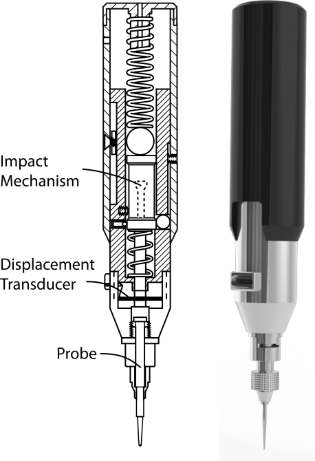
Figure 1 shows a schematic of the Osteoprobe, which we have named our novel, hand-held RPI, instrument. The main components of the Osteoprobe include an impact generation mechanism, a displacement transducer, and a probe. The displacement transducer consists of a custom full bridge strain gage pattern mounted on a flexure and connected as a Wheatstone bridge. The probe is manufactured out of hardened stainless steel and has a 90° conical tip with a tip diameter of approximately 375 μm and a tip sharpness radius less than 10 μm.
Figure 1.
Diagram (left) and rendering (right) of the Osteoprobe. The primary components of the Osteoprobe include an impact mechanism, a displacement transducer, and a probe. The impact mechanism creates constant force impacts which push the probe into the sample. The displacement transducer, consisting of four strain gauges mounted onto a flexure and connected in a bridge circuit, measures the indentation distance increase from the impact.
Indentation mechanics
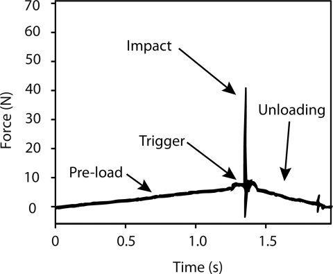
The Osteoprobe is designed to create a micro-indentation in bone, both in the laboratory and in vivo. To do this properly there are four important operations that occur at different forces and rates which combine to create a reproducible micro-indentation in bone. The operations are: (1) pre-load, (2) triggering, (3) impact, and (4) unloading. These operations are labeled in a force vs. time graph to clearly show the forces on the sample during a test cycle (Figure 2).
Figure 2.
Force-time plot during indentation on bone. During the loading phase, typically lasting around 1 s, the probe of the instrument is manually pushed into the bone up to a maximum loading force of 10 N. Once the loading force reaches 10 N, an indentation is triggered. The indentation impacts the probe into the bone with a peak force of 40 N (30 N due to the impact alone). After the impact, the operator removes the instrument during the unloading phase. The measured parameter is the indentation distance increase from the impact. The short duration of the impact (of order 1 ms) means that the time for the measurement is short relative to the times over which a living patient or horse moves. Thus the measurement is relatively insensitive to movement of the patient or horse.
The pre-load securely anchors the test probe into the bone before the primary indentation occurs. The force is high enough to ensure the probe is through any periosteum and other soft tissue covering the bone while keeping the initial indentation into the bone minimal. The cycle occurs over approximately one second at a constant linear rate from 0 N up to 10 N.
The next operation is triggering. Once the pre-load force reaches 10 N, the trigger mechanism will initiate an impact, which is the primary force used to create the indentation. The instrument keeps the triggering force reproducible from indent to indent. The impact occurs in less than a millisecond (approximately 0.25 ms). For bone, the impact force peaks at 30 N. The impact force does change depending on the material being tested, but the impulse from the impact remains constant at 0.01 N s. The impact moves the probe farther into the bone, creating an increase in its displacement; this increase in displacement is the primary measurement the Osteoprobe records.
After the impact, the force decreases back to 0 N during the unloading stage. This occurs as the instrument is removed from the sample by the operator.
Operation technique
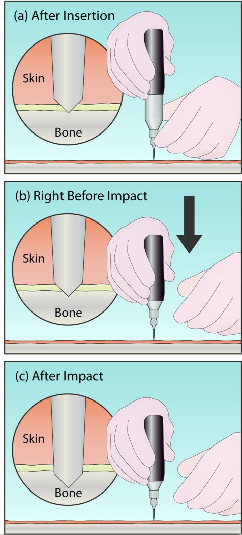
Figure 3 shows the technique for testing a sample with the instrument. Before the impact (Figure 3a), the operator pushes (or pokes) the instrument through the soft tissue with their lower hand. The operator's lower hand is placed on the sterile guide, just above the probe. Once the probe is through the skin and periosteum, and resting on the bone (circular magnified view), the lower hand is only used to stabilize the instrument laterally. The upper hand, on the outer housing, is used to push downwards, shown in Figure 3b, compressing the primary spring until the trigger device initiates the impact. This impact will be initiated at a preset force (10 N). To ensure that this force remains constant between different impacts, it is critical that the lower hand be neither adding to nor subtracting from this force when the impact is triggered. For example, in the middle panel the lower hand is shown having released the instrument before impact to avoid errors caused in this manner. In practice, especially for bone that is not horizontal, it is usually necessary to maintain some contact with the lower hand to keep the probe at the desired test site on the bone—the overall goal is to avoid pushing down or pulling up with forces comparable to the 10 N trigger force.
Figure 3.
Basic operation of the Osteoprobe. (a) Initially, the lower hand is used to push the instrument through the soft tissue by pressing down on the guide, just above the probe. (b) Once ready to indent, the lower hand is removed to prevent adding additional downward force on the instrument. The upper hand then begins to compress the instrument. This causes the probe to sink slightly into the bone (see detail (b)). (c) Once the instrument is fully compressed, the impact mechanism triggers, generating an impact. The probe is pushed farther into the sample by the impact. The distance the probe moves into the sample beyond its position right before the impact is the indentation distance increase from the impact. The BMS is defined as 100 times the ratio of the average indentation distance increase from the impact into a calibration phantom (Poly (methyl-methacrylate), PMMA, plastic) over the indentation distance increase from the impact into bone.
The magnified circular view displays the displacement into the bone after insertion (Figure 3b), but just prior to impact (this is the reference point from which the indentation distance increase from the impact is measured) and after impact (Figure 3c). This indentation distance increase from the impact (excluding the indentation due to the 10 N insertion force prior to triggering) is the primary measured parameter from the output signal, and can be subsequently converted to bone material strength as described in Sec. 2D.
Once the indentation is complete, the operator can move the test probe over approximately 2 mm from the last indentation site to perform another test if necessary. Typically at least five indentations are performed per sample due to heterogeneity.
Parameters measured
BMS is a normalized parameter that the Osteoprobe's software automatically calculates from the measurements acquired by the instrument. The raw voltage is calibrated to obtain the indentation distance increase from the impact (measured in μm). Again, this is the distance the probe travels into a sample due to the impact force alone; it does not include the indentation made during the loading of the 10 N trigger force. The indentation distance increase from the impact parameter can be used as a measurement for materials other than bone, though in the specific case of bone, we use a derived parameter, BMS, which is defined as 100 times the ratio of the average indentation distance increase from the impact into a calibration phantom (poly (methyl-methacrylate), PMMA, plastic) over the indentation distance increase from the impact into the sample. Thus, if a sample was exactly as resistant to indentation as the phantom, the BMS would be 100. If the sample was more susceptible to fracturing, its BMS would be lower than that of the phantom, which is the case for most bone.
Another parameter, unnormalized BMS, is commonly used in this manuscript to describe the effects of instrument variables. Unnormalized BMS is defined as 100 times the ratio of the ideal (perfectly normal to the sample and a sharp probe) indentation distance increase from the impact into PMMA (150 μm) divided by the indentation distance increase from the impact into the sample. The purpose of this parameter is to see the effect of different variables such as probe sharpness, indentation angle, etc. If we normalized to the calibration phantom after each test, as is done in the standard BMS, our values would stay relatively consistent when the variable is changed. Normalization is good for clinical testing because the normalized BMS will, at least partially, correct for variations in these variables; for example, variation due to a dull tip would be partially corrected.
The indentation distance increase from the impact of the test probe into the sample induces micro-fractures. With easily fractured bone, less force is required to create a micro-fracture, thus the test probe will be able to indent farther into the sample, creating a large indentation distance increase from the impact. Thus, the larger the indentation distance increase from the impact, the smaller the BMS.
INSTRUMENTAL VARIABLES
Angular dependence
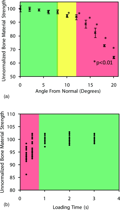
The Osteoprobe indents the sample with a conical probe, and is designed to be held perpendicular to the test specimen. To determine the effect of operating the instrument at angles other than normal, an experiment was performed where the sample was mounted at angles varying from 0° to 20° deviating from normal in 2° intervals. The sample size was 10 indentations at each interval into the calibration phantom. Figure 4a shows the results from the study.
Figure 4.
Operator effects. (a) Angular dependence of the unnormalized BMS output from the Osteoprobe. A calibration block was tested at different angles ranging from 0° to 20° off normal. At 10° and higher, the values were significantly smaller than normal. The instrument should always be held less than 10° off of normal from the test specimen for accurate results. It is important to note that the unnormalized BMS values are all normalized with respect to the calibration material being perfectly normal to the sample. The standard BMS would compensate for angles off of normal if the calibration phantom was tested at the same angle off normal. (b) Comparison of values obtained from three different operators indenting a standard sample at different loading times. If one indents the sample while compressing the instrument rapidly, the unnormalized BMS values are lower than expected and have large variance. As one increases the loading time (duration of compression), the values stabilize. This occurs when the loading time is greater than 1 s.
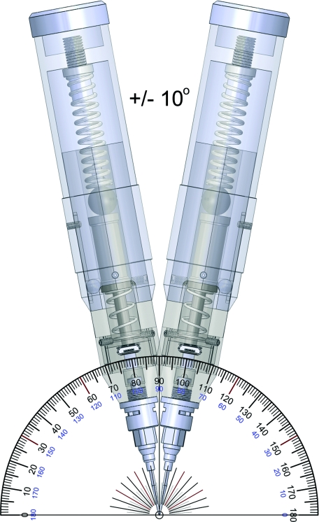
The results show that once the angle between the instrument and sample is ±10° from normal or larger, the results are significantly different (p < 0.01) than the optimal normal position. While ±10° sounds like a small range, we have found that it is easily accomplished and have generated a rendering to show the workable angular range (Figure 5). The operator must pay careful attention to the orientation at which they are holding the Osteoprobe to ensure accurate readings. Additionally the operator should always keep an eye on the Osteoprobe during testing. If the operator looks away, at the computer screen for example, as they compress the spring, they typically do not maintain a perpendicular relationship between the sample and the instrument.
Figure 5.
Rendering of the acceptable angular range of holding the instrument with respect to the sample. As shown in Figure 4, if the instrument is within this ±10° range then the values for unnormalized BMS will be within a few percent of the measured value being exactly perpendicular to the sample.
Speed dependence
Changing the duration of compression (downward actuation of the outer housing) during indentation can also affect the values measured. In order to determine the magnitude of the effect, we had multiple operators indent a standard sample. We chose multiple operators for this test, rather than building a machine that could maintain precise compression rates because the Osteoprobe will, in the end, be operated by hand and so it makes sense to see how well individual operators can maintain a time sufficient to give reproducible results. Each operator performed 10 tests on the sample at different speeds ranging from a very fast 0.25 s to a considerably slower 3 s per indent. A loading time of at least 1 s is sufficient to obtain consistent results, loading times less than that give false readings, showing a smaller than expected BMS (Figure 6b). This is presumably because there is less time for creep to deepen the 10 N indentation before the impact. Thus the impact starts in a shallower hole and can thus go deeper during the impact.
Figure 6.
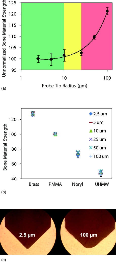
Effects of tip radius. (a) Experiment results of varying tip radii on the unnormalized BMS. The results show that as the probe dulls the unnormalized BMS increases significantly from the ideal value measured with a sharp tip. Much of this problem is, however, currently solved by always normalizing by the actual measured value of the indentation distance increase from the impact on a calibration phantom with the same tip. We anticipate that probes will be mass produced, sharp, and only used once per patient so that the need for this normalization we have been using during the development stage may vanish. Thus, in (b) the radius of the probe tip does not affect BMS values on the materials tested and we would hope that this is also true for measurements on patients, who typically fall in this same range of values. This will, however, have to be confirmed with actual measurements on patients to be sure. (c) Images taken under an optical microscope showing the extreme probe radii.
Probe sharpness dependence
The probe has a 90º conical tip. The tip is sharpened to have a radius of 10 μm or less. To see the effect of a dull tip, we conducted an experiment with six different probes with a tip sharpness radius range of 2.5–100 μm. A calibration phantom was used as the test specimen and 10 indentations were conducted with each tip. The results are displayed in Figure 6a.
Once the tip radius exceeds 10 μm on the probe the unnormalized BMS begins to climb dramatically. We want to emphasize that the “Unnormalized Bone Material Strength” uses the standard indentation distance increase from impact as 150 that would be obtained with ideal conditions, rather than the measured value with that specific probe. This error in measurement is due to the tip being too dull and not indenting as far as a sharp tip would with the same amount of force. The acceptable range for tip sharpness is 10 μm or less for the impact provided by the Osteoprobe.
Another experiment was conducted on several different materials with the same probes of varying tip radii (2.5–100 μm). Instead of using the unnormalized BMS, we measured the true BMS that the software would output for the operator. This experiment was conducted to see if normalizing with respect to the calibration phantom would correct for varying tip radii on materials across the range we would expect to see in patients. The results (Figure 6b) show that the BMS indeed corrects for varying tip radii from 2.5 μm to a dull 100 μm tip (image of tips shown in Figure 6c).
Although BMS corrects for a wide range of tip radii, it is important to note that as the probe exceeds 10 μm it is much more difficult to pierce the soft tissue; therefore all tips are sharpened to a 10 μm or less tip radius.
Sample mass dependence
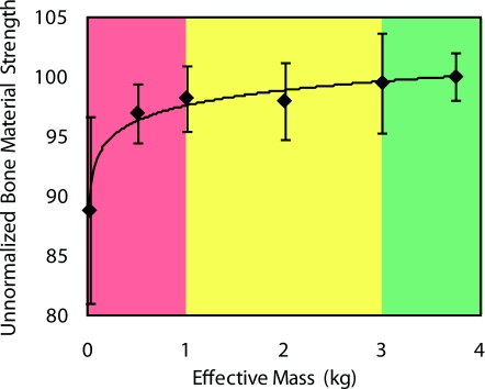
If the effective mass of the sample is too low, the Osteoprobe will not only indent it, but will also push away the sample during the 1 ms impact time measurement. Such tests will provide an excessively large value of indentation distance from the impact and thus a small value of BMS. To avoid these sort of issues, it is important to hold samples in a fixture with sufficient mass: at least 1 kg, preferably over 3 kg. An experiment was conducted with the results displayed in Figure 7. With an effective sample mass less than 1 kg, the BMS is undervalued significantly. As the mass increases to about 3 kg, the BMS reaches the ideal value of 100 for PMMA. This concern is notable for small animal bones with little mass. Additionally, the indentations have been optimized for human and horse bone testing: they need to be validated for smaller animal bones since indentation might be too deep.
Figure 7.
Effect of the sample mass on the unnormalized BMS. The Osteoprobe requires for the sample to have a large enough mass to stay substantially stationary during the very fast indentation cycle ( >1 ms). A calibration phantom (PMMA) was clamped with varying masses to determine the mass required to obtain reliable results. The results show that the effective sample mass, due to the fixture or the mass of the sample itself, needs to be 1 kg or larger. The unnormalized BMS increases towards 100 and eventually levels off as the effective sample mass increases to about 3 kg.
Thermal dependence
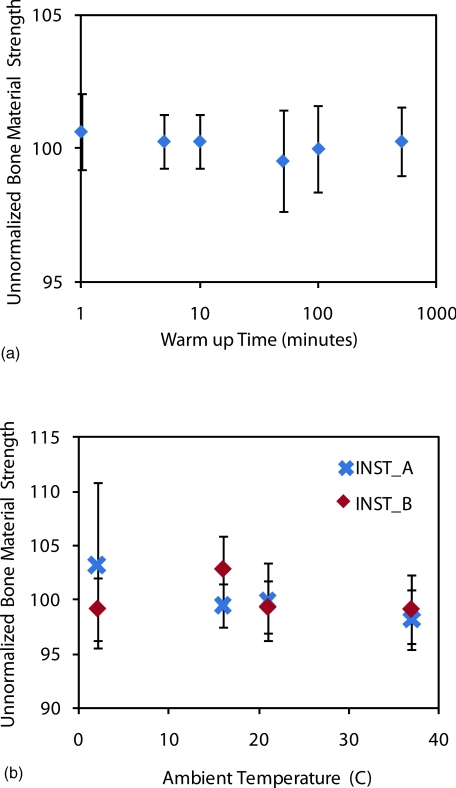
Two experiments were conducted to determine if there was an effect on the Osteoprobe's data due to thermal effects. The first experiment tested to determine if there were any “warm up” issues with turning on the electronics and hand-held unit. The electronics were turned on and the unit was tested immediately. This continued at different time intervals all the way up to over 8 h. The results show a consistent BMS for the calibration phantom of 100 for the entire duration (Figure 8a). These results suggest that there is no requirement for warming up the instrument and that it can be tested immediately after it is turned on as well as tested after being on for a long duration with accurate BMS measurements.
Figure 8.
Thermal dependence and warm up time of instrument. (a) The warm up time of the instrument is negligible and long term drift is less than a few percent. (b) Thermal dependence of the unnormalized BMS from the Osteoprobe. A calibration phantom (PMMA) was tested at different temperatures ranging from 2 ºC to 37 ºC. The unnormalized BMS for all the temperatures are very close to the ideal BMS value of 100 for the calibration phantom. There is no significant (p > 0.05) effect on the results from the Osteoprobe due to varying environmental temperatures ranging from 2 ºC to 37 ºC.
The next experiment tested thermal effects due to the environmental temperature. One would expect the average room temperature in a typical clinic to be near 20 °C; however, we tested at an extreme range of temperatures (2 ºC to 37 ºC) in order to determine if there is any effect on the measured values for a calibration phantom. Two instruments were used (A and B) and at each room temperature trial, the instruments were allowed to reach equilibrium with the ambient room test temperature by storing the instrument in the room for 30 min before testing began. The results from this test are shown in Figure 8b. Over the extreme range of temperatures, there was no significant difference between the two extremes for both instruments. Thus, from these results, we conclude that there is negligible effect on the measurements acquired by the Osteoprobe due to temperature change.
OPERATOR TRAINING
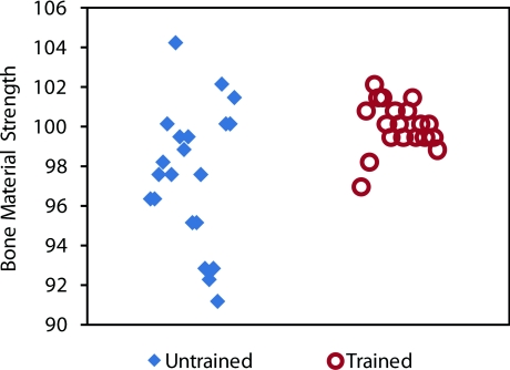
Once the instrument variables were analyzed and optimized, as discussed in Sec. 3, a training manual was created for the proper use of the Osteoprobe. To determine the amount of training required, an inexperienced user was handed the instrument and conducted 20 tests on a calibration phantom without reading the training manual. After these initial tests, the user was given 5 min to read the training manual. Then the second tests were conducted. The results are shown in Figure 9.
Figure 9.
Effects of operator training. The untrained operator has a lower mean for BMS (typically due to holding the instrument at an angle over 10º from normal and/or indenting too rapidly) and a much higher spread. The same operator after only 5 min of training can achieve the proper mean of approximately 100 and a much lower standard deviation. The Osteoprobe was designed to be a simple hand-held instrument for testing the BMS, which is shown with these results.
The untrained operator's results were far from the ideal: the average BMS was below 100 and there was a large spread in the data. After only 5 min of reading the training manual, the same operator had a measured BMS mean around 100, as it should be, and had a spread of data that was less than half of the untrained tests. These results suggest that with only 5 min of training an operator can obtain accurate and reproducible results with the Osteoprobe, making the instrument very user-friendly. One particular user learned that they were compressing the primary spring too fast and not keeping the instrument normal to the sample, therefore getting low readings as discussed above. After training, the user started to count “one-one thousand” during the spring compression to ensure at least a second compressing before the instrument triggered the impact. The user paid close attention to the angle of indentation. With the aid of the training manual a new operator can be trained and can obtain reproducible and accurate results very quickly.
MATERIAL TESTING VALIDATION
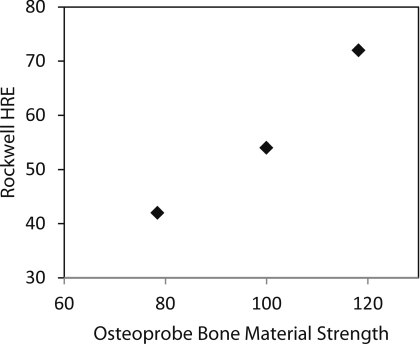
Three calibration blocks were tested with both the Osteoprobe and a Rockwell Hardness tester. The Rockwell Hardness tester used was a Goko Seiki Works Model 3S. The calibration materials used were brass, PMMA, and Noryl. Due to the Osteoprobe's great testable range, the calibration materials had to span a large range in hardness, thus there was not an ideal Rockwell scale, however, measurements were taken with the Rockwell E scale for comparison. A 1/8 in. diameter steel sphere was used with a load of 100 kg. Figure 10 shows the relationship between the Rockwell Hardness and BMS, indicating a close correlation between the two.
Figure 10.
Correlation between Rockwell Hardness Scale E testing and BMS of three calibration materials. PMMA, Brass, and Noryl were measured with both a Rockwell Hardness testing machine and the Osteoprobe. There is a close correlation between BMS and hardness.
DISCUSSION
With the parameters optimized, as discussed in Sec. 3, a simple five-minute training session allows new users to produce results comparable to those of an experienced user. The main parameters that affect the operation of the Osteoprobe are the angle at which the sample is indented, the rate at which the sample is indented, the sharpness of the probe used, and the mass of the sample. All of these factors are relatively simple to correct for by (1) making sure to properly hold the instrument normal when performing indentations, (2) mentally count “one-one thousandth” in the head to keep the rate of compression constant, (3) inspect probe tips regularly, and (4) insure the effective mass of the sample is greater than 1 kg or, alternatively, firmly holding the sample in a fixation device. In conclusion, the Osteoprobe is an easy-to-use hand-held instrument which could potentially provide measurements of the material strength of bone in laboratory samples or in human and animal clinical trials.
ACKNOWLEDGMENTS
We thank the National of Institutes of Health (NIH) (Grant No. RO1 GM 065354) for support of this work and the individuals who donate their bodies and tissues for the advancement of education and research. We also thank and acknowledge Dr. Adolfo Diez Perez for coming up with the name “Bone Material Strength” for our normalized parameter.
Currently the Osteoprobe is not available commercially. The measurements reported here were done with prototype instruments, but Active Life Scientific, Inc. may, in the future, produce a commercial version of this instrument if there is demand for it. PH is a member of Active Life Scientific, which sells the Biodent product line of RPI instruments for research use only.
References
- Diez-Perez A., Guerri R., Nogues X., Caceres E., Pena M. J., Mellibovsky L., Randall C., Bridges D., Weaver J. C., Proctor A., Brimer D., Koester K. J., Ritchie R. O., and Hansma P. K., J. Bone Miner. Res. 25(8), 1877–1885 (2010). 10.1002/jbmr.73 [DOI] [PMC free article] [PubMed] [Google Scholar]
- Hansma P., Yu H., Schultz D., Rodriguez A., Yurtsev E. A., Orr J., Tang S., Miller J., Wallace J., Zok F., Li C., Souza R., Proctor A., Brimer D., Nogues-Solan X., Mellbovsky L., Pena M. J., Diez-Ferrer O., Mathews P., Randall C., Kuo A., Chen C., Peters M., Kohn D., Buckley J., Li X., Pruitt L., Diez-Perez A., Alliston T., Weaver V., and Lotz J., Rev. Sci. Instrum. 80(5), 054303 (2009). 10.1063/1.3127602 [DOI] [PMC free article] [PubMed] [Google Scholar]
- Hansma P., Turner P., Drake B., Yurtsev E., Proctor A., Mathews P., Lulejian J., Randall C., Adams J., Jungmann R., Garza-de-Leon F., Fantner G., Mkrtchyan H., Pontin M., Weaver A., Brown M. B., Sahar N., Rossello R., and Kohn D., Rev. Sci. Instrum. 79(6), 064303 (2008). 10.1063/1.2937199 [DOI] [PMC free article] [PubMed] [Google Scholar]
- Hansma P. K., Turner P. J., and Fantner G. E., Rev. Sci. Instrum. 77(7), 075105 (2006). 10.1063/1.2221506 [DOI] [Google Scholar]
- Lyyra T., Jurvelin J., Pitkanen P., Vaatainen U., and Kiviranta I., Med. Eng. Phys. 17, 395 (1995). 10.1016/1350-4533(95)97322-G [DOI] [PubMed] [Google Scholar]
- Toyras J., Lyyra-Laitinen T., Niinimaki M., Lindgren R., Nieminen M. T., Kiviranta I., and Jurvelin J. S., J. Biomech. 34, 251 (2001). 10.1016/S0021-9290(00)00189-5 [DOI] [PubMed] [Google Scholar]
- Hvid I., “Mechanical Testing of Bone and the Bone-Implant Interface” in Penetration Testing of Bone Using the Osteopenetrometer (CRC, Boca Raton, 2000). [Google Scholar]
- Chavassieux P., Seeman E., and Delmas P. D., Endocr. Rev. 28(2), 151–164 (2007). 10.1210/er.2006-0029 [DOI] [PubMed] [Google Scholar]
- Vashishth D., Crit. Rev. Eukaryot Gene Expr 15(4), 343–357 (2005). [DOI] [PubMed] [Google Scholar]
- Currey J. D., J. Biomech. 12, 459–469 (1979). 10.1016/0021-9290(79)90031-9 [DOI] [PubMed] [Google Scholar]


