Abstract
Personalized energy (PE) is a transformative idea that provides a new modality for the planet’s energy future. By providing solar energy to the individual, an energy supply becomes secure and available to people of both legacy and non-legacy worlds, and minimally contributes to increasing the anthropogenic level of carbon dioxide. Because PE will be possible only if solar energy is available 24 hours a day, 7 day a week, the key enabler for solar PE is an inexpensive storage mechanism. HX (X = halide or OH−) splitting is a fuel-forming reaction of sufficient energy density for large scale solar storage but the reaction relies on chemical transformations that are not understood at the most basic science level. Critical among these are multielectron transfers that are proton-coupled and involve the activation of bonds in energy poor substrates. The chemistry of these three italicized areas is developed, and from this platform, discovery paths leading to new HX and H2O splitting catalysts are delineated. For the case of the water splitting catalyst, it captures many of the functional elements of photosynthesis. In doing so, a highly manufacturable and inexpensive method has been discovered for solar PE storage.
1. Introduction
Global energy need will roughly double by mid-century and triple by 2100 owing to rising standards of living of a growing world population.1 Most of that demand is driven by 3 billion low-energy users in the non-legacy world and by 3 billion people yet to inhabit the planet over the next half century. To hold atmospheric CO2 levels to even twice their preanthropogenic values and at the same time meet the increased energy demand of these 6 billion additional energy users, will require invention, development, and deployment of carbon-neutral energy on a scale commensurate with, or larger than, the entire present-day energy supply from all sources combined.2–4 The capture and storage of solar energy at the individual level – personalized solar energy – drives inextricably towards the heart of this energy challenge by addressing the triumvirate of secure, carbon neutral and plentiful energy.5 Because energy use scales with wealth,1 point-of-use solar energy will put individuals, in the smallest village in the non-legacy world and in the largest city of the legacy world, on a more level playing field. Moreover, personalized energy (PE) is secure because it is highly distributed and the individual controls the energy on which she/he lives. Finally, the possibility of generating terawatts of carbon-free energy may be realized by making solar PE available to the 6 billion new energy users by high throughput manufacturing. Notwithstanding, current options to harness and store solar energy at the individual level are too expensive to be implemented, especially in a non-legacy world. The imperative to science is to develop new materials, reactions and processes that enable the capture, conversion and storage of solar energy to be sufficiently inexpensive to penetrate global energy markets.3 Most, if not all, of these materials and processes entail a metallic element. Accordingly, the subject of inorganic chemistry is especially germane to delivering solar PE to our planet.6
Because society relies on a continuous energy supply and solar energy is diurnal, a key enabler for PE is an inexpensive storage mechanism. Most current methods of solar storage are characterized by low energy densities and consequently they present formidable challenges for large scale solar PE implementation. The energy densities of compressed air (~0.5 MJ/kg at 300 atm), flywheels (~0.5 MJ/kg), supercapacitors (~0.01 MJ/kg), and water pumped uphill (0.001 MJ/kg at 100 m) are modest. The same is true of batteries, which are often discussed as an effective energy storage medium for solar energy. Though considerable efforts are currently being devoted to battery development,7 most advances have little to do with energy density but rather they are concerned with power density (i.e. the rate at which charge can flow in and out of the battery) and lifetime. Energy densities of batteries are low (~0.1 – 0.5 MJ/kg) with little room for improvement because the electron is stored at a metal center of an inorganic network juxtaposed to an electrolyte. The volume in which the electron and attendant cation reside and transfer is thus limited by the physical density of materials. Some of the lightest elements in the periodic table, and hence lowest physical densities, are already used as battery materials and consequently energy densities of batteries have approached a ceiling. Continuing along this line of reasoning, the smallest volume element in which electrons may be stored is in the chemical bond. It is for this reason that the energy density of liquid fuels (~50 MJ/kg) is ≥102 times larger than the best of the foregoing storage methods; H2 possesses an even greater energy density at 140 MJ/kg. Indeed, society has intuitively understood this disparity in energy density as all large scale energy storage in our society is in the form of fuels.
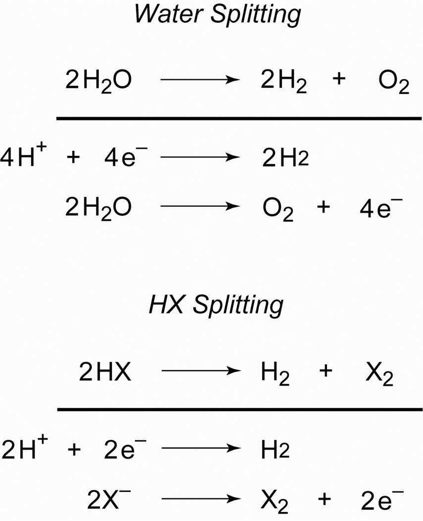
HX (X = halide or OH−) splitting is a particularly attractive storage mechanism for solar PE,
| (1) |
| (2) |
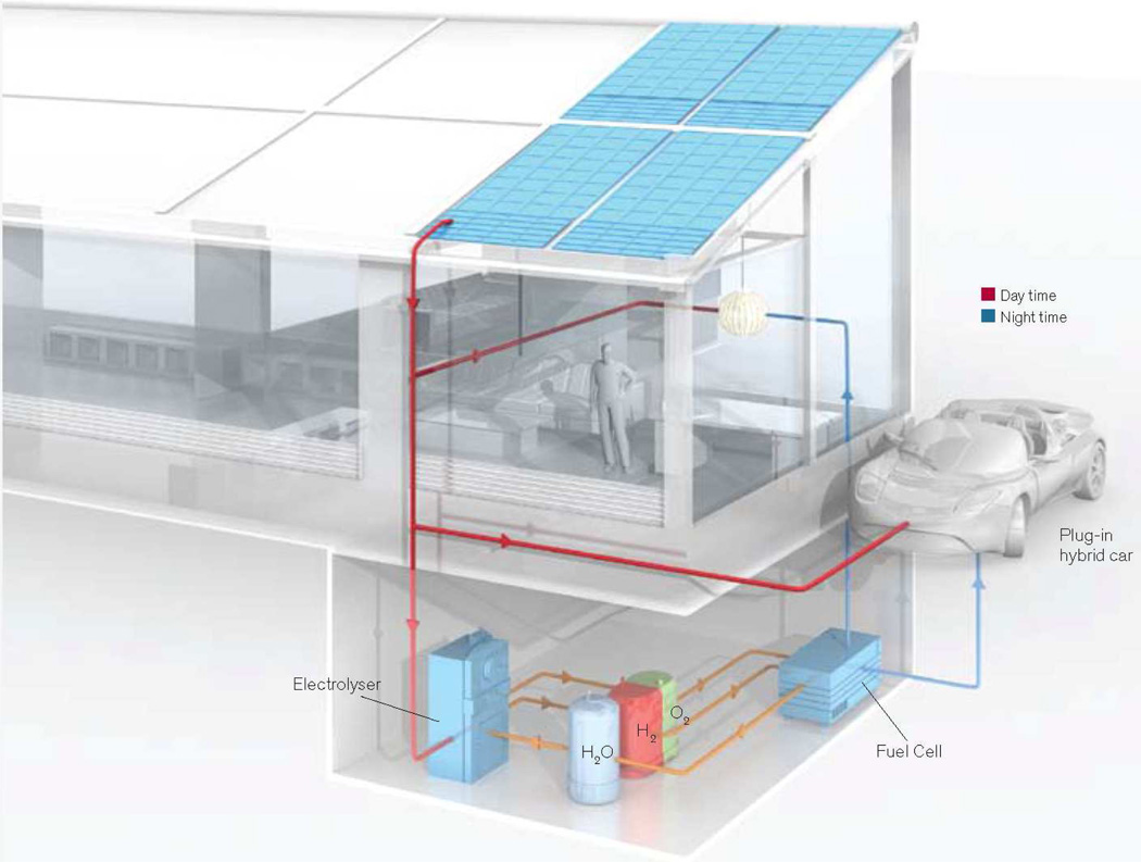
If X = Cl, both HX and H2O splitting are of the same formal potential at standard conditions and consequently store approximately the same molar equivalent of energy. To understand the storage capacity of HX splitting, consider eq (1) within the context of the average American home, which uses ~20 kW-hr of electricity per day. Given that the heat of formation of H2O is 237 kJ mol−1, then the storage of 20 kW-hr can be achieved by splitting only 5.5 L of water per day. On this basis, a system such as that shown in Figure 1 can provide sufficient PE to support an individual’s daily life. Of course, compression efficiencies for H2 and the efficiency of the fuel cell must also be factored into the system, thus increasing the amount of water that needs to be split. The point here is that energy storage needed for solar PE is currently within reach of the chemist with the design of catalysts that effectively promote eqs (1) or (2) in the forward (solar storage) and reverse (fuel cell) directions.
Figure 1.
An energy independent home delivers the individual personalized energy. Reproduced with permission from MIT and Technology Review.
Successful HX splitting at high efficiencies demands significant discovery on several fronts. Scheme 1 separates eqs (1) and (2) into their half reactions. The overall transformation involves either 1 × 2e (for H2) and 1 × 2e (for X2) or 2 × 2e (for H2) and 1 × 4e (for O2) multielectron processes to which protons must be coupled intimately. If they are not, then prohibitively high-energy barriers are imposed on both half reactions. Moreover, HX splitting reactions confront sizable thermodynamic barriers that are intrinsic to the energy storage process. Whereas chemists have mastered catalytic reactions of energy rich bonds in downhill reactions, the efficient catalytic bond-making/breaking reactions of energy-poor substrates are not generally realized at a molecular center or on a surface. This is especially pertinent to the HX splitting problem since photointermediates invariably contain strong metal-X bonds, which need to be activated to close a catalytic cycle. In this context, a toolbox for HX splitting is:
multielectron transformations
rearrangement of low energy bonds to high energy bonds (i.e. running reactions uphill with an energy input)
proton-coupled electron transfer
The HX splitting problem shares basic chemical commonalities to the activation of other small molecules of energy consequence as well,8,9 including CO2, N2, CH4, H2 and O2. For this reason, (a) – (c) more generally underpin the molecular chemistry of renewable energy. Our research effort to systematically develop the chemistry of processes (a) – (c) is presented. With these “new colors” on the chemistry palette, a picture of solar PE emerges.
Scheme 1.
2. A Chemist’s Toolbox for Catalysis of Consequence to Renewable Energy
2.1. Multielectron Chemistry
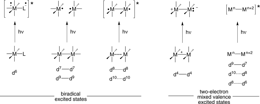
The endergonic nature of energy conversion chemistry demands an energy input in order to drive the reaction. Often that energy input comes from light, which produces an electronic excited state from which the reaction proceeds. The oxidation-reduction reactions of electronically excited transition metal complexes customarily proceed by one electron. Multielectron reactivity is achieved by coupling consecutive one-electron processes to a remote homogeneous or heterogeneous site, which is capable of storing multiple redox equivalents. This general strategy has largely defined the light-to-energy conversion schemes of the past four decades.10–14 Such conformity in multielectron design finds its origins in the nature of the excited state (Figure 2), which at the most general level is the same despite the many different types of transition metal photoreagents. The photochemistry of mononuclear d6 metals, for which tris(bipyridyl)ruthenium(II) is the archetype, originates from a metal-to-ligand charge transfer excited state15–19 in which electrons localized on the metal and ligand are triplet-paired. Biradical excited states are also obtained from binuclear complexes, but in different guises. The dσ-dσ* (or dπ*-dσ*) excited states of d7—d7 and d9—d9 complexes are short-lived and dissociative, producing a •M/M• biradical pair.20–22 Metal-based biradicals are tethered by a single bond upon the production of a dσ*pσ excited state of d8⋯d8 and d10⋯d10 complexes.23,24 For each of the three types of excited states, the biradical naturally leads to two-electron processes, one electron at a time,18,23,25 and a controlled multielectron chemistry is difficult to achieve.
Figure 2.
Electron configurations for the diradical excited state that is characteristic of most transition metal complexes and the two-electron mixed valence excited state of bimetallic compounds explored in the author’s research program.
2.1.1. The Multielectron Excited State
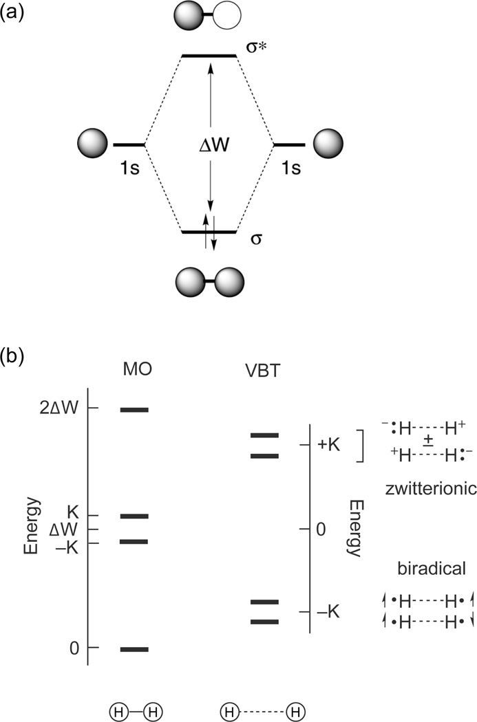
To develop a discrete multielectron excited state, we returned to the most basic element of chemistry, the two-electron-two-center (2e-2c) bond. This electronic configuration gives rise to four states, which for H2 are derived from the 1σσ, 3σσ*, 1σσ* and 1σ*σ* configurations shown in Figure 3. The 1Σu(1σσ*) and 3Σu(3σσ*) excited states involve one-electron promotion and thus lie about the one-electron orbital splitting energy (ΔW), separated by twice the exchange energy (K). Because electrons reside in a molecular orbital (MO) that is well distributed about the two H atoms, the distance between the electrons, rij, is large and hence K is small. Consequently, the energies of 1Σu(1σσ*) and 3Σu(3σσ*) are well accounted for by ΔW in the MO limit. The 21Σg(1σ*σ*) excited state is derived from a two-electron promotion and hence it lies at 2ΔW.
Figure 3.
The molecular orbital diagram of H2 (top) and the energy level diagram for H2 described in the limits of molecular orbital theory (MOT) and valence bond theory (VBT) (bottom). ΔW is the one-electron orbital splitting energy and K is the two-electron exchange energy.
The 2e-2c manifold holds a central place in bonding descriptions. It was originally described by Heitler and London for valence bond theory (VBT)26 and subsequently by Pauling27 and Mulliken28 in their formalism of molecular orbital theory (MOT). Although the state diagram for strongly overlapping orbitals (i.e., the MO limit) such as the one shown in Figure 3 is taught at the most introductory level of chemistry, it is not generally appreciated when the orbitals are weakly coupled. Coulson and Fischer described this case for “stretched hydrogen” in their landmark paper that unified VBT and MOT.29 At long distance, the 1s orbitals of H2 overlap marginally. Two low energy biradical states arise from one electron in each orbital with spins opposed in the 1σσ ground state and parallel in the 3Σu(3σσ*) excited state. Because the orbitals are weakly overlapping, ΔW is small and these states are of similar energy. Of pertinence to multielectron chemistry, the two higher energy 1Σu(1σσ*) and 21Σg(1σ*σ*) configurations correlate to zwitterionic singlet excited states that are derived from the antisymmetric and symmetric linear combinations of electrons paired in one orbital of either center. The high energy of the zwitterionic states (2K above the ground state) results from the sizable exchange energy that is incurred upon pairing two-electrons in atomic-like orbitals. Unlike the biradical state, the electrons are paired in the zwitterionic state and hence this type of excited state is pre-disposed to two-electron reactivity.
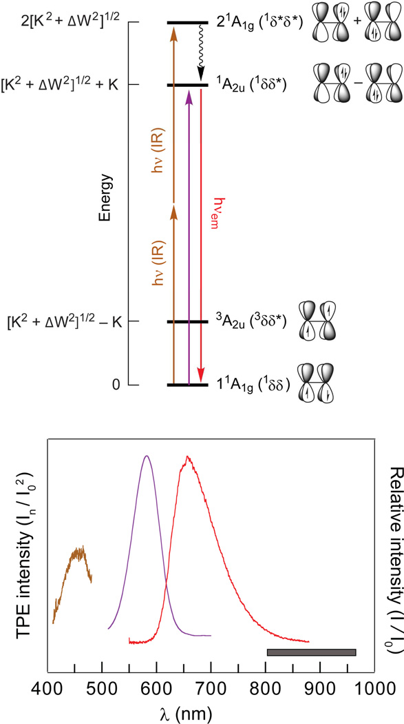
The four states of the 2e-2c bond had not been directly measured experimentally prior to our work. The reason is simple: The excited states of the four electron manifold are antibonding and thus dissociative. This challenge is especially acute for the highest energy singlet state, which amounts to the promotion of two electrons into an antibonding orbital. It is difficult to stretch a σ bond or twist a π-bond and maintain a stable configuration for spectroscopic delineation of the energetics of that bond.30 Conversely, the overlap of the dxy orbitals on individual metal centers presents a stable 2e-2c δ-bond, which is ideally adapted for spectroscopic investigation when incorporated within the sterically constrained coordination environment of quadruple metal-metal bonded species (M−4−M).31 In this case, the four states in D4h symmetry resulting from the electron occupation of the δ HOMO and δ* LUMO are 1A1g(1δδ), 3A2u(3δδ*), 1A2u(1δδ*) and 21A1g(1δ*δ*), each of which has been independently characterized.
With the formulation of the δ bond,32,33 the identification of the 1A1g(1δδ) ground state in M−4−M species soon followed.34 The strong polarization and dipole allowedness of the δ → δ* transition led to the identification of the 1A2u(1δδ*) excited state early in the study of the electronic absorption spectroscopy of these compounds.35 The 3A2u(3δδ*) state is sufficiently low in energy, as first predicted by Hay,36 that it can be populated at reasonable temperatures, thus allowing its energy to be determined from temperature dependent measurements of the magnetic susceptibility37 and of ligand 31P{1H} NMR signals.38 Against this backdrop, we sought to observe the 21A1g(1δ*δ*) excited state. We located the 21A1g(1δ*δ*) excited state, which is two-electron excitation forbidden by the selection rules of conventional optical spectroscopy, by two-photon laser-induced fluorescence (TP-LIF).39,40 The TP-LIF experiment is schematically represented in Figure 4. The 21A1g(1δ*δ*) state is accessed with two near-IR photons, followed by internal conversion to the emissive 1A2u(1δδ*) excited state. The 21A1g(1δ*δ*) excitation profile is constructed by monitoring the intensity of the 1A2u(1δδ*) luminescence as the infrared excitation wavelength (normalized in intensity) is scanned in and out of resonance with the 21A1g(1δ*δ*) state. The assignment of the two-photon state follows from power dependence measurements and polarization ratios over the entire two-photon absorption cross-section. This result, together with the previous spectroscopic measurements of the 3A2u(1δδ*) and 1A2u(1δδ*) excited states, provided the first complete description of the four states that characterize a 2e-2c bond in a discrete molecular species.31
Figure 4.
(Top) Qualitative energy level diagram for the δ/δ* orbital manifold arising from the overlap of dxy orbitals of M–4–M complexes in accordance with a valence bond model. The 1δ*δ* excited state can be accessed by two-photon near-IR absorption and detected via laser-induced fluorescence (LIF) of the 1δδ* excited state. The energy of the states is given in terms of the one-electron orbital splitting energy ΔW and the two-electron exchange energy K. (Bottom) Emission (red), absorption (purple) spectra and two-photon LIF excitation (brown) spectra of Mo2Cl4(PMe3)4 in 3-methylpentane at room temperature. The two-photon LIF excitation spectrum is superimposed at twice the laser excitation energy. The spectral region over which the incident dye-laser excitation was scanned is indicated by the gray box.
The overall wavefunction is defined by ΔW, K and the overlap integral, S, of the two dxy orbitals.41 With three state energies on hand, these three spectroscopic unknowns may be unambiguously calculated and the coefficients, and hence degree of ionicity, of the excited state wavefunctions may be determined.31,39 Our results on M2X4(PP) (M = Mo(II), W(II); X = halide; PP = bridging phosphine), M = Mo or W) reveal that the 1δδ ground state possesses 20% ionic character, which increases to 80% in the 1A2u(1δδ*) excited state. These two-photon results unequivocally establish significant zwitterionic character of the 1A2u(1δδ*) excited state,
| (3) |
The zwitterionic 1A2u(1δδ*) excited state is of sufficient lifetime to permit excited state reactivity, though we found that this is not a sufficient condition for multielectron photochemistry. Although the 1A2u(1δδ*) excited state is ionic, it is nonpolar because :M−−3−M+ and M+−3−M:− are equal contributors to the linear combination of eq (3) as long as a center of inversion is maintained within the molecule and its environment. Intermolecular or intramolecular perturbations are needed to remove the center of inversion and consequently engender an electronic asymmetry. Transient spectroscopy of M−4−M complexes reveal that the two-electron mixed-valence character of the zwitterionic excited state is trapped by an intramolecular ligand rearrangement to yield an edge-sharing bioctahedral (ESBO) intermediate with two electrons localized on one metal center of the bimetallic core,42
 |
(4) |
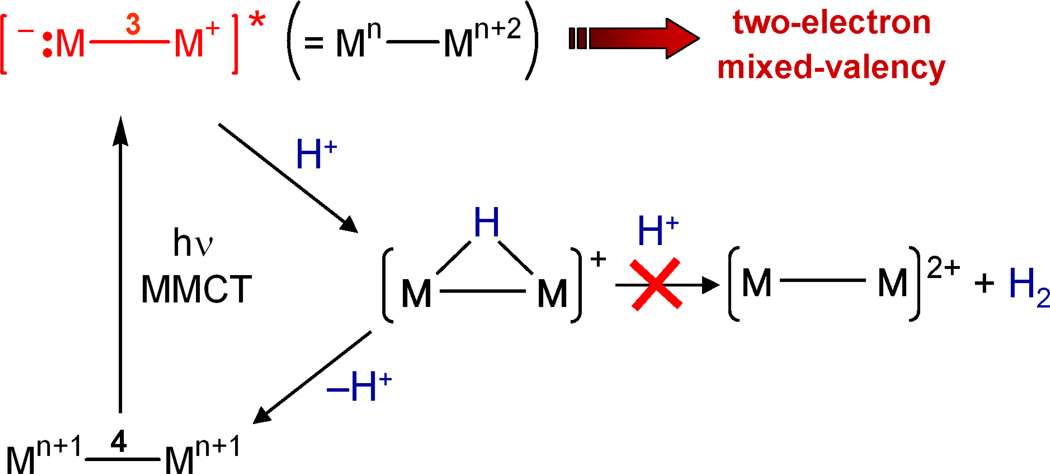
The resultant M+−3−M:− zwitterion reacts in discrete two-electron steps: M2X4(PP)2 (M = Mo(II), W(II); X = halide; PP = bridging phosphine) complexes undergo one-photon two-electron addition of YZ substrates such as alkyl iodides43,44 and aryl disulfides42 to yield M2(III,III) ESBO complexes. The same zwitterionic intermediate supports two-electron elimination reactions of isovalent ESBO complexes (the photodriven reverse of eq (4)).45 Whereas the two electron zwitterionic intermediate may be trapped by a proton as well (see Figure 5), the ensuing species is not hydridic enough to be protonated to produce hydrogen.
Figure 5.
Metal-to-metal charge transfer (MMCT) produces a zwitterionic excited state in which the formal oxidation states of the metal differ by two. Transient absorption studies show that the excited state reacts with a proton to make a hydride, which back reacts to produce the M–4–M grounds state. The hydride is not trapped by a second proton to produce hydrogen.
2.1.2. Two-Electron Mixed Valency
The two-electron reaction intermediate of M−4−M complexes is produced by light excitation of a metal-to-metal charge transfer transition. This two electron character resulting from electron pairing within the binuclear core of M−4−M species is quite unique. Most excited states are derived from the population of MOs that are delocalized over the entire bimetallic core and, consequently, it is not appropriate to think about electron pair localization at one metal or another. For this reason, multielectron schemes based on zwitterionic excited states are difficult to generalize and new approaches to multielectron reactivity must be developed. To this end, we set a research course to incorporate two-electron mixed-valency into the delocalized ground state of bimetallic complexes.
2.1.2.1. Metal Based Two-Electron Mixed Valence Complexes
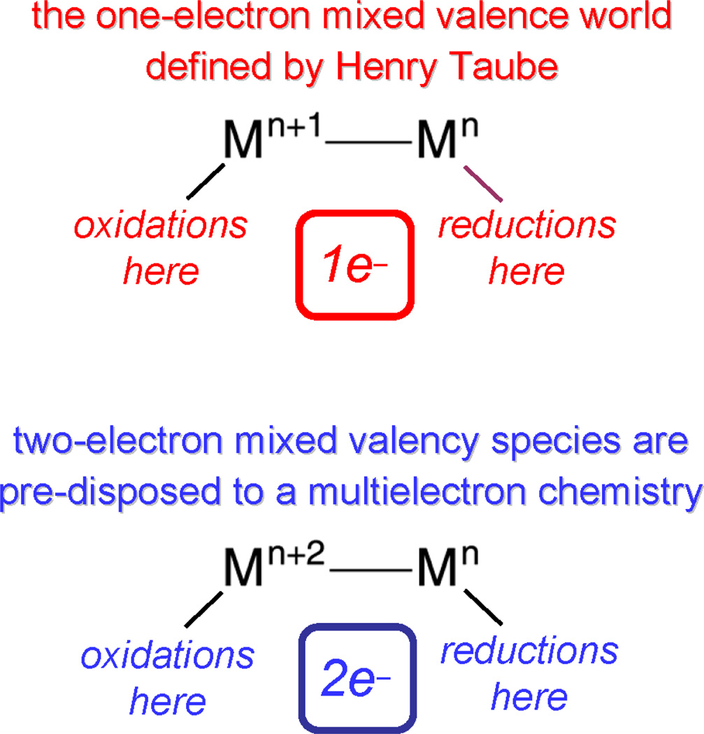
The zwitterionic excited state may be formulated as a two-electron mixed-valence species as depicted in Figure 5. This formalism is useful because it provides connectivity to a large body of inorganic chemistry that was pioneered by Taube.46 Mixed valency in molecular compounds is typically accommodated at metal centers whose formal oxidation states differ by one.47–49 In these complexes, reactivity is confined to single electron oxidations and reductions of the constituent Mn and Mn+1 centers, respectively.50–55 Extrapolating from this one-electron formalism, two-electron mixed valency of bimetallic cores provides entry into a multielectron oxidation-reduction chemistry (Scheme 2).56 Redox cooperativity may be established between the individual metal centers of a Mn⋯Mn+2 mixed-valence core such that two-electron oxidations may be promoted at a Mn+2 center and two-electron reductions may be promoted at a Mn center.
Scheme 2.
A metal-based two-electron mixed valency in a delocalized electronic ground state is attained by the disproportionation of a redox symmetric core,
| (5) |
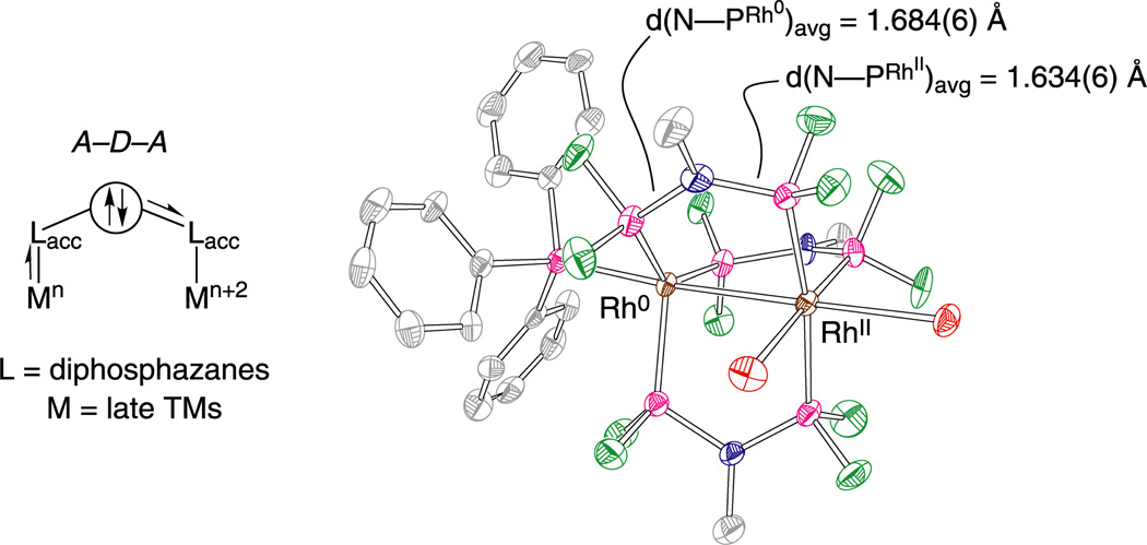
Eq. (5) may be driven to the right by designing ligands that incorporate antithetical design elements: two π-accepting moieties with a π-donor bridgehead (A–D–A)57–61 or two π-donating moieties with a π-accepting bridgehead (D–A–D).62–64 The A–D–A ligand motif is achieved by placing an amine bridgehead between two electron-deficient phosphines (PRF2) or phosphites (P(ORF)2). The A–D–A ligands, bis(difluorophosphino)methylamine (dfpma, CH3N(PF2)2) and bis(bistrifluoroethoxyphosphino)methylamine (tfepma, CH3N[P(OCH2CF3)2]2) shown in Chart 1, exhibit a particular proclivity for promoting the internal disproportionation of binuclear M2I,I cores to M20,II cores65 for the metals of rhodium57,58 and iridium.59–61,66 X-ray crystal structures reveal a pronounced asymmetry in the diphosphazane framework upon ligation to a bimetallic core derived from the asymmetric stabilization of metals that differ by two in their formal oxidation. The result is consistent with π-donation of the amine bridgehead lone pair to the PRF2 bonded to MII. With MII → PRF2 π-backbonding diminished, the PRF2 group acts more like a simple σ-donor, stabilizing the high-valent MII metal center. Correspondingly, with the nitrogen lone pair electron density channeled away from the second neighboring PRF2 group, its strong π-accepting properties are maintained, and hence M0 is stabilized. As highlighted by the arrows in Figure 6, this electronic asymmetry is reflected in an alternating bond length pattern for the Rh0—P—N—P—RhII framework.
Chart 1.
Fluorophosphine ligands that promote two-electron mixed-valency of bimetallic cores.
Figure 6.
(Left) The three-atom dfpma ligand shown in Chart 1 possessing an electron donor bridgehead (D) between two π-accepting moieties (A), which can be used to stabilize two-electron mixed-valence cores. The stabilization of a mixed-valence core by the A–D–A stereoelectronic ligand motif results in differing bond orders indicative of an asymmetric electronic distribution. (Right) A crystal structure of Rh20,II(dfpma)3Br2 displays the long-short bond alteration of the ligand backbone. Reproduced from ref. 8.
Our success in using Mn⋯Mn+2 species to drive two- and four-electron transformations along ground and excited state pathways57–59 established two-electron mixed valency as a useful design concept for the development of multielectron reaction schemes. The two-electron mixed valence core is particularly effective in hydrogen management and production.67,68 Intermetal redox cooperation for hydrogen atom migration appears to be a critical determinant for the addition and elimination of hydrogen from Mn⋯Mn+2 cores. The migration proceeds through a bridging hydride transition state,
| (6) |
The ability of the diphosphazane ligand framework to accommodate the electronic and steric asymmetry without excessive reorganization as the hydrogen migrates among terminal and bridging coordination sites appears to be essential for the H2 reactivity of eq (6).
The bridging transition state of eq (6) is similar to that proposed for the so-called dinuclear elimination mechanism for the bimolecular reductive elimination reaction of mononuclear species.69–71 Some metal hydrides, which exhibit sluggish intramolecular elimination, are extremely unstable in the presence of a second complex capable of attaining coordinative unsaturation. This enhanced reactivity has been ascribed to the following transformation,
 |
(7) |
in which R is a hydride, alkyl or acyl group. Bimolecular elimination of this type is only possible when one of the ligands is hydride, which must migrate to the bridging position for elimination to occur. For the case of the two-electron mixed-valence compounds, the requisite coordinative unsaturation and hydride are already present. With the neighboring metals of the Mn⋯Mn+2 core working in concert, the hydrogen atom migrates to and from the critical bridging position to promote facile H2 addition and elimination,67 respectively. In this regard, we view the chemistry of the two-electron mixed-valence complexes as the unimolecular analog to the dinuclear elimination reaction.
2.1.2.2. Ligand Based Two-Electron Mixed Valence Complexes
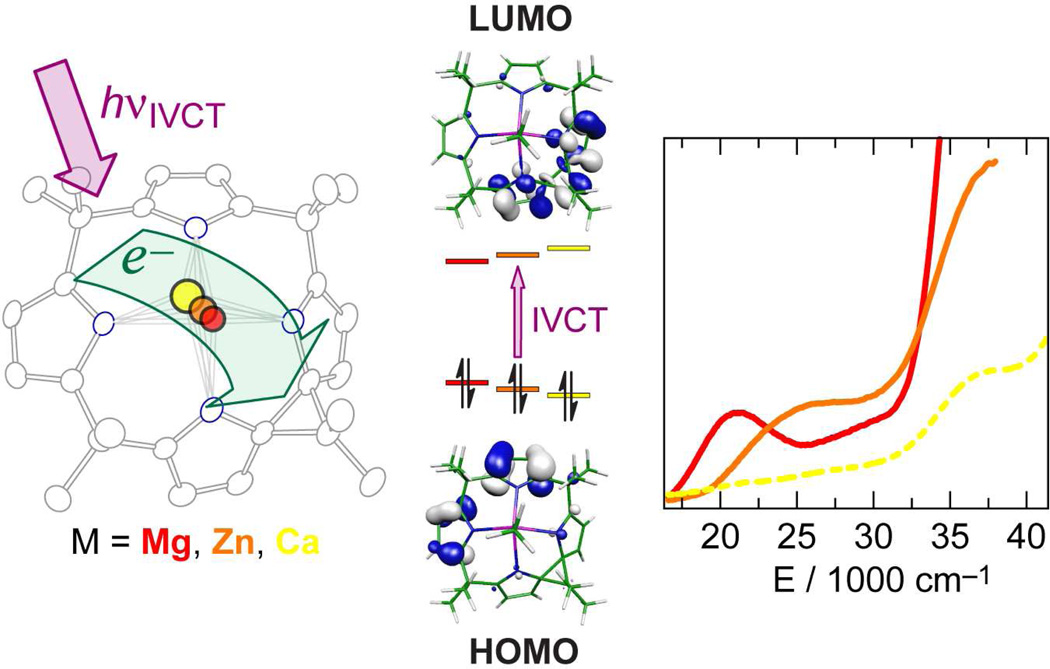
The design concept of two-electron mixed valency is expanded by using the ligand framework of porphyrinogens as the multi-electron/hole reservoir, as opposed to the bimetallic core. Oxidation of the tetrapyrrole ring of porphyrinogen results in one or two spirocyclopropane rings (Δ), formed by C–C coupling between the α-carbons of neighboring pyrroles.72 This transformation effectively stores two or four oxidizing equivalents in the macrocyclic ring. Prior to our studies, however, the generality, characterization and practical use of the ligand-based redox chemistry of porphyrinogens was hindered by the presence of redox-active axial ligands and/or polynuclear copper/iron halide counterions.73–75 Accordingly, we developed new synthetic methods that afforded porphyrinogens with redox inactive metals (e.g., Mg, Zn and Ca) and redox-inert and spectroscopically silent counterions.76 In this way, we were able to unveil the redox properties of the macrocycle by electrochemistry, and isolate and characterize the three ligand oxidation states, [LM]2−, [LΔM] and [LΔΔM]2+.77 Figure 7 summarizes the results from structural, computational and spectroscopic results of the intermediate oxidation state, [LΔM], which is best described as a localized two-electron mixed-valence complex. DFT calculations reveal that the highest occupied molecular orbitals are localized on the reduced half of the macrocycle whereas the lowest unoccupied molecular orbitals are localized on the oxidized half of the porphyrinogen (Figure 7, middle). Consistent with this formulation, the intense orange color of [LΔM] arises from an intraligand intervalence charge transfer (IL-IVCT) from the reduced dipyrrole half of the macrocycle to its two-electron oxidized dipyrrole neighbor.
Figure 7.
(Left) Thermal ellipsoid plot (50% probability level) for the solid-state structure of the two-electron mixed valence Mg porphyrinogen compound, [LΔMg(NCMe)]•CH2Cl2. (Middle) Computed frontier Kohn-Sham orbital diagram of the HOMO and LUMOs of [LΔMg(NCMe)] showing the localization of the electron density that gives rise to the ligand-to-ligand intravalence charge transfer transition (IVCT). (Right) UV-visible absorption spectra of [LΔMg] (—, red), [LΔZn] (– –, orange) and [LΔCa] (---, yellow) in CH2Cl2. Reproduced with permission from the Royal Society of Chemistry
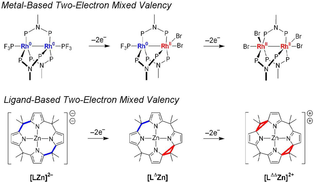
Figure 8 highlights the parallel between ligand- and metal-based two-electron mixed valency. For both cases, the two-electron mixed-valence intermediate: (1) is the linchpin that couples the two-electron chemistry of the individual redox centers (dipyrroles in the case of porphyrinogen, rhodium centers in the case of the bimetallic complex), (2) is the structural composite of the symmetric oxidized and reduced congeners and (3) has lowest energy electronic transitions that are confined to the two-electron mixed-valence core. The ligand-based approach, however, differs from that of the metal-based approach in one important aspect. Because coordination geometry is inextricably linked to metal oxidation state, two-electron/hole storage in the metal-based approach must be accompanied by alterations of the primary coordination sphere. Conversely, for the porphyrinogens, two-electron/hole storage occurs in the macrocycle periphery, decoupled from the acid-base chemistry of the metal. This orthogonalization between redox storage and metal coordination geometry offers a new design element for using two-electron mixed valency to promote multielectron reactivity. This chemistry is contingent on relaying redox equivalents from the macrocycle to a redox-active central metal. We have demonstrated redox communication between the metal and ligand of iron porphyrinogens78 in which redox cycling between the iron and the porphyrinogen ring occurs in an single three-electron redox step between [LFeIII]− and [LΔΔFeII]2+ species.79 In conjunction with this multielectron relay chemistry, protons may coordinate at the α-pyrrole carbon,80 which is the same site that is involved in two-electron redox storage. Hence, the proton and electron redox equivalents are collected at the same site. The coupling of the electron and proton suggest that porphyrinogens may permit hydrogen to be generated at the porphyrinogen periphery.
Figure 8.
The porphyrinogen ligand as a two-electron mixed-valence scaffold and its redox parallel to the dirhodium system. The two-electron reduced and oxidized parts of the molecules are color coded blue and red, respectively.
2.2. Rearrangement of Low-to-High Energy Bonds
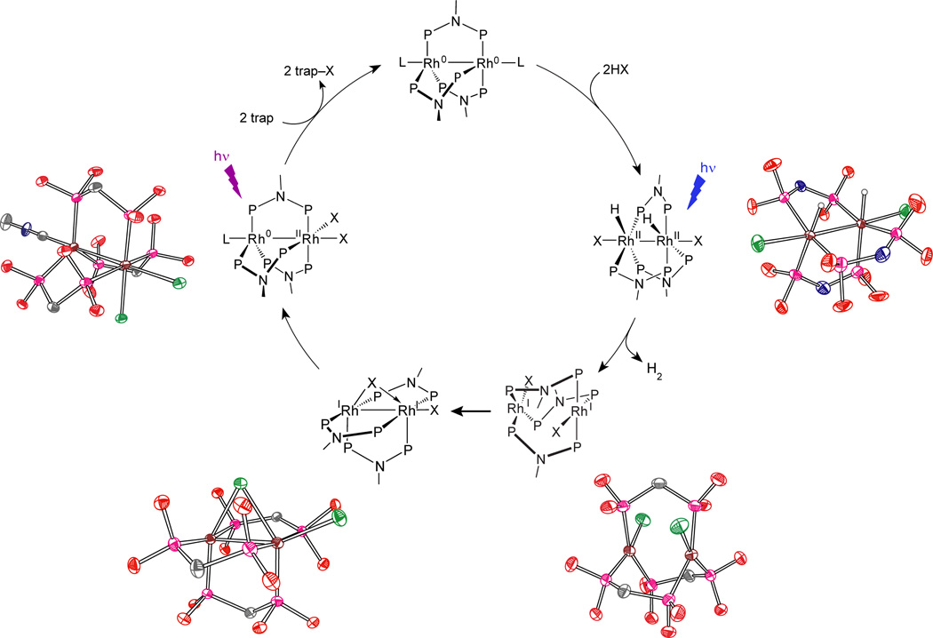
When low energy metal-ligand bonds can be activated, photocatalytic hydrogen cycles involving two-electron mixed valence complexes may be realized. For the dirhodium dfpma complex described in Section 2.1.2.1, the metal-halide bonds of the two-electron mixed valence intermediate, Rh0—RhII(X)2, must be surmounted for H2 photocatalysis to be achieved.81 The photocatalytic hydrogen generation cycle shown in Figure 9 has been constructed for the dirhodium dfpma complex in homogeneous solution.82 Relevant intermediates of the photocycle have been identified based on the isolation and crystallization of dfpma, tfepma and tfepm (bis(bistrifluoroethoxyphosphino)methane, H2C[P(OCH2CF3)2]2) dirhodium analogs.83 Circling clockwise about the photocycle shown in Figure 9, the HX addition product to the Rh20,0 core has been isolated by H2 addition to the Rh20,II dihalide tfepma complex. Photolysis of this Rh2II,II dihydride-dihalide complex drives the prompt photoelimination of one equivalent of H2 to generate a blue (X)RhI⋯RhI(X) intermediate, which may be crystallized when the bimetallic core is coordinated by tfepm. The hydrogen elimination is quantitative and efficient, by virtue of the gaseous state of the photoproduct. The valence symmetric, primary (X)RhI⋯RhI(X) photoproduct is unstable with respect to internal disproportionation to the Rh0—RhII(X)2 core. The disproportionation proceeds by folding a terminal halide into the bridging position of the bimetallic core; this intermediate may be isolated for a diiridium center ligated by tfepm. Photoexcitation of the Rh0—RhII(X)2 complex leads to trap-assisted halogen elimination and regeneration of the Rh20,0 complex for re-entry into the photocycle.
Figure 9.
The complete photocycle for H2 generation by the Rh2 dfpma photocatalyst from nonaqueous solutions containing HCl or HBr. Identification of the intermediates in the cycle is based on the chemistry of dirhodium and diiridium dfpma, tfepma and tfepm analogs, the crystal structures of which are shown.
The overall photoefficiency for H2 production by the Rh20,0 dfpma catalyst is ~1%. This photoefficiency is the same as that measured independently for the photoconversion of Rh20,II(dfpma)3Cl2L to Rh20,0(dfpma)3L2 (Φp = 7 × 10⁻³).57 These observations suggested to us that the activation of the Rh—X bond is determinant to overall photocatalytic activity. An increase in the quantum efficiency for hydrogen photocatalysis is therefore equated to increasing the photoefficiency for halogen elimination from the binuclear metal core. The reductive elimination of dihalogen, however, is extremely rare owing to the stability of the metal halide bond together with the low bond energy of the halogen product. Moreover, the production of dihalogen is invariably endergonic. Even if dihalogen elimination is achieved, the back reaction is thermodynamically favored and fast, resulting in no net reaction. For these reasons, the reductive elimination of halogen from metal centers proceeds only in the presence of a halogen trap.
Traps are problematic in that the trap–X bond is sufficiently exergonic that energy storage is obviated. In addition, the detailed process by which photoelimination proceeds is obscured as both X• and X2 can react with most traps. Improved efficiencies for H2 production therefore require increased quantum yields for M–X bond activation and new strategies to prevent the back reaction of primary photoproducts.
We have succeeded in surmounting both challenges by incorporating Au and Pt into bimetallic cores.84 The [PtIIIAuII(dppm)2PhCl3]PF6 (dppm = bis(diphenylphosphino)methane) complex photoreduces to its PtIIAuI congener upon irradiation in the presence of 2,3-dimethyl-1,3-butadiene with a maximal quantum yield of 5.7%,85 which is nearly a 10-fold increase over halogen elimination from the Rh0—RhII(X)2 bimetallic core. Even higher quantum yields are obtained from more highly oxidizing PtIII—PtIII cores. Pt2III,III(tfepma)2Cl6 undergoes efficient two-electron photoreduction (Φ = 38%) to Pt2III,I(tfepma)2Cl4 under irradiation of λexc = 355 – 510 nm at high trap concentrations:86
 |
(8) |
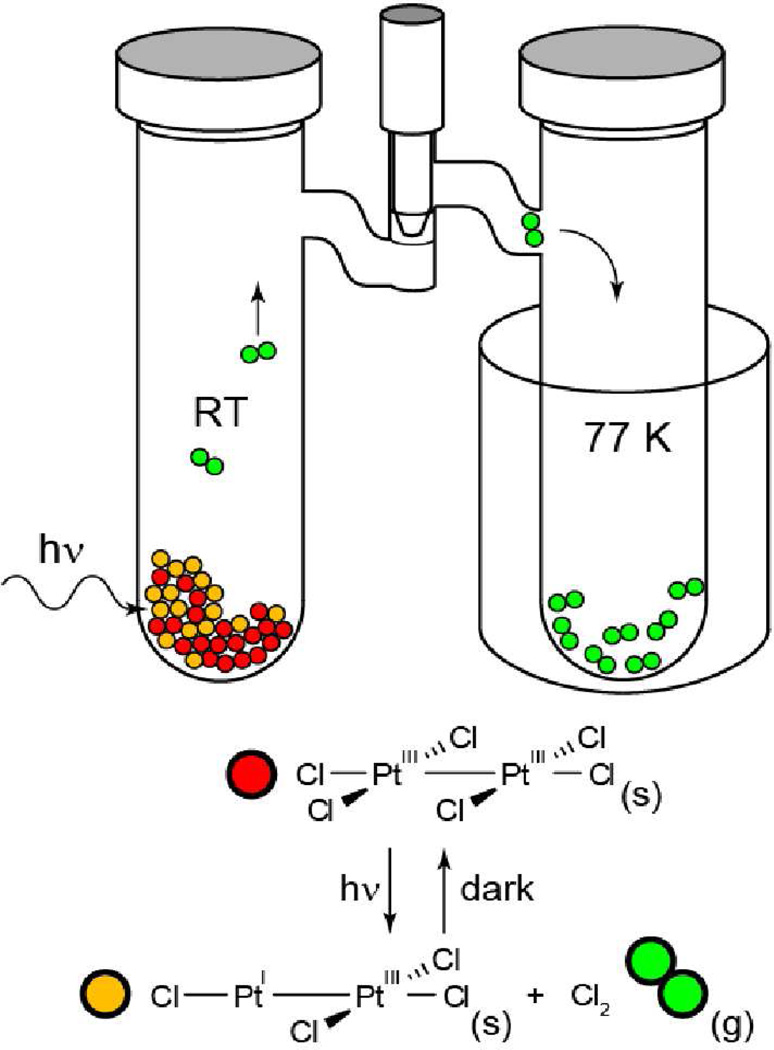
Because of the high quantum yield for halogen photoelimination, the reaction can be induced in the solid state in the absence of a trap. The experiment shown in Figure 10 provides the first example of authentic, trap-free X2 reductive photoelimination from a transition-metal center. Of perhaps greater significance, Cl2 adds facilely to Pt2I,III tfepma photoproduct. The photoreaction therefore is an authentic energy storing photoreaction. The uphill photoreaction has been generalized to include AuIII centers of mono- and bimetallic cores coordinated by phosphines and bisphosphines, respectively.87 In contrast to diplatinum photochemistry, which is driven from an excited state of considerable dσ* parentage,88 the digold chemistry appears to be derived from a ligand-to-metal charge transfer (LMCT) excited state. Though LMCT photochemistry has been conventionally confined to one-electron redox transformations,89 a four-electron photoreduction of halogen from Au2III,III PP complexes proceeds as follows,
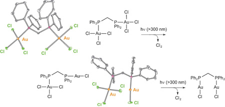 |
(9) |
As with diplatinum compounds, the reaction occurs smoothly in the solid state in the absence of trap; the X2 back reaction is prevented by virtue of the production of a volatile X2 photoproduct.
Figure 10.
A schematic of the apparatus used to perform solid state photoelimination of halogen gas from bimetallic Pt2 tfepma and Au2 bisphosphine complexes. The color-coded reactants and photoproducts are that for eq. (8).
With X2 photoelimination realized, the stage is set to unify H2 and X2 photochemistry of two-electron mixed valency in a single system and thus furnish an authentic HX (X = halide) splitting scheme. These studies are currently underway.
2.3. Proton-Coupled Electron Transfer
The activation of all energy-related molecules requires the coupling of electron equivalents to proton equivalents. Without this coupling, large reaction barriers confront small molecule conversion, thus imposing large overpotentials, and hence energy inefficiency. For instance, the H2 half reaction proceeds at 0 V vs NHE when the reaction proceeds in a discrete two-electron, proton-coupled step. If the electron and proton are uncoupled, then the reaction proceeds through a H• radical and consequently confronts a barrier of 2.3 V vs NHE. The uncoupled one-electron/one-proton reactions to produce HO• radicals are equally imposing. The challenge to lowering the activation barrier therefore arises in the intimate coupling of the electron and proton, prompting us to begin a research program targeting proton-coupled electron transfer (PCET) reactions.
2.3.1. The Mechanism of PCET
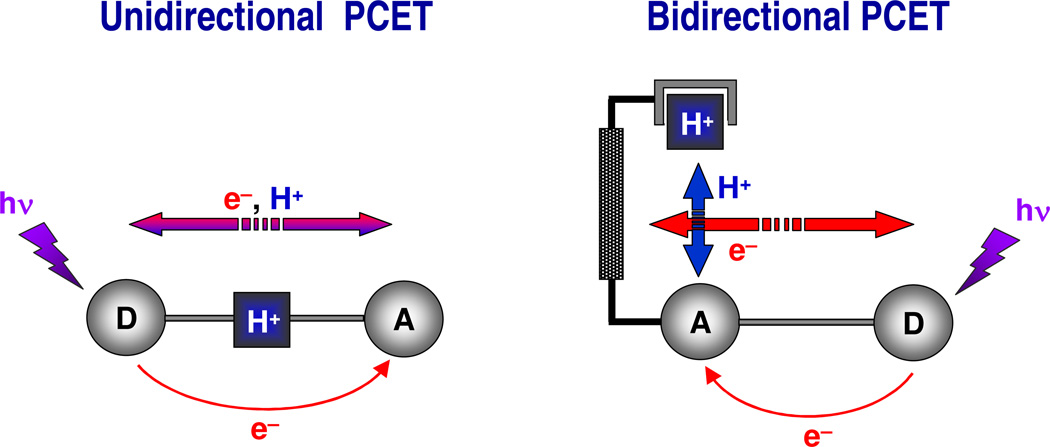
The coupling of a proton and electron has long been known in a thermodynamic sense, first explicitly defined to account for the pH dependence of redox couples.90 In subsequent years, the kinetics of proton-electron coupling was inferred from free energy relations and kinetic isotope effects of reactant to product conversions of enzymatic,91,92 organic93–95 and inorganic substrates.96,97 Notwithstanding, a predictable framework for PCET, at least to the extent that exists by way of Marcus theory, was absent because the electron and proton had not been isolated in a PCET event. To this end, we turned our efforts toward isolating the PCET step and directly measuring the kinetics of the reaction. To do so, we created the unidirectional and bidirectional PCET networks shown in Figure 11.98–100 The unidirectional D---[H+]---A constructs (D = ET donor, A = ET acceptor, ---[H+]--- = proton interface) provided tangible kinetic benchmarks for PCET reactions and stimulated the development of theories to describe PCET.101,102 In these constructs, both the electron transfer (ET) and proton transfer (PT) distances are defined, with the caveat that the proton can be located anywhere within the interface. PCET is triggered by laser excitation of the donor or acceptor and the PCET event is captured with time-resolved spectroscopy. Along its journey from donor to acceptor, the electron must negotiate the proton within the interface. Systems with symmetric interfaces such as cyclic carboxylic acid dimers103 permitted the effect of the electronic coupling matrix element on PCET to be isolated whereas asymmetric interfaces, especially those composed of amidinium-carboxylate104–110 and amidinium-sulfonate interactions,112–114 permitted the effect of the Franck-Condon term on PCET to be defined.115 From these studies it was found that the distinguishing characteristic of a PCET reaction arises from the response of the polarization of the surrounding environment to the motion of the electron and proton.
Figure 11.
Supramolecular assemblies created to investigate PCET mechanisms for electron and proton transport along colinear and orthogonal pathways. In each system, the photoinduced electron transfer must negotiate the transfer of a proton. Reproduced from ref. 8.
At a mechanistic level, PCET fundamentally differs from traditional hydrogen atom transfer (HAT).116 In a traditional HAT, the electron originates from the X–H bond (typically sigma), and transfers co-linearly with the proton to become part of the new H–Y bond. From the perspective of PCET, it is reasonable for the electron and proton to transfer adiabatically in a synchronous manner. However, in the PCET reactions of small molecules at metal active sites, the electron and proton are often site-differentiated and consequently considerable charge separation may accompany the activation reaction. This is especially true of water activation where the proton is transferred to the oxo ligand with concomitant reduction of the metal. Though electron and proton movement may not originate or terminate at the same point, the proton can affect the electron transport. Furthermore, the same electron and proton do not have to couple throughout an entire transformation. As the electron moves, it may encounter different protons. All that is required for a PCET event is that the kinetics and thermodynamics of electron transport depend on the position of a specific proton or set of protons at any given time. Nevertheless, the protons and electrons must couple; if they do not, then large kinetic barriers are imposed on the activation reaction.
PCET is intrinsically a quantum mechanical effect since both the electron and proton tunnel as a result of the overlap between the donor and acceptor wavefunctions.117,118 The proton rest mass is ~2000 times that of the electron and, as such, the proton wavelength is ~40 times shorter than that of an electron at a fixed energy. Consequently, PT is fundamentally limited to short distances whereas the electron, as the lighter particle, may transfer over much longer distances. For this reason, the unidirectional PCET networks impose an inherent limitation on controlling the length-scale disparity between PT and ET because the network is assembled by the hydrogen bonds of the proton interface. PT distances are therefore confined to the hydrogen bond length scale imposed by the ---[H+]--- bridge.
Conversely, bidirectional PCET networks afford a facile means to manage the disparate length scales of the electron and proton.119,120 The bidirectional PCET model systems schematically represented in Figure 11 orthogonalize the ET and PT coordinates. The PT distance is established by a rigid scaffold that poises an acid-base group above an ET conduit. In these “Hangman” architectures, a carboxylic acid or amidine is positioned over porphyrin121–124 or salen125–127 platforms via a xanthene or dibenzofuran spacer. By appending an electron acceptor or donor to the redox platform, a PCET reaction may be established with PT to or from the hanging group. The Hangman constructs allow for the incisive investigation of the role of proton tunneling in PCET because the PT distance may be independently adjusted from the ET distance.128
2.3.2. Hangman and Pacman Porphyrins for the PCET Activation of Oxygen
We have shown that bidirectional PCET at Hangman platforms can be exploited to activate O—O129 bonds, from which catalysis may be derived.130–136 Proton transfer from the acid-base hanging group in MIII (M = Fe or Mn) Hangman porphyrin and salen peroxide complexes yields high valent metal-oxo intermediates via exclusive 2e− bond heterolysis.137,138 Homolytic O—O bond cleavage—a 1e−, 1H+ transformation—is circumvented by coupling a single proton to drive the 2e− heterolytic bond cleavage event.
The electrophilic oxo of the Hangman platform exhibits reactivity patterns essential for water activation.139,140 The oxo reacts with peroxide, which dismutates to O2 and H2O, and it is also present as a crucial intermediate in the reduction of O2 to H2O. This latter transformation is important to our goals of developing a solar fuels chemistry because the conversion is the microscopic reverse of the O—O bond forming chemistry that is needed for water splitting. Specifically we have used the O2 reduction chemistry of Pacman Co2II,II bisporphyrins as a roadmap to water splitting.141 Oxygen is efficiently reduced to water within the Pacman cleft but only if a proton is present. Proton transfer to the [Co2O2]+ superoxo core of [Co2III,III(bisporphyrin)(O2)]+ triggers a two-electron transfer. If the superoxo is insufficiently basic, one-electron reduction of the [Co2III,III(bisporphyrin)(O2)]+ ensues in the absence of a proton and peroxide is produced. Thus by coupling a proton to a multielectron transfer, the O—O bond is cleaved. The overall mechanism provides several valuable lessons for the design of a water splitting catalyst. First, a high metal-oxo bond strength, and attendant kinetic barrier, is circumvented with the use of a late metal such as cobalt. Second, the four equivalents needed for water splitting is afforded from a multi-metallic active site. And finally, the use of protons is critical for O—O bond cleavage. Similarly, proper proton management may be expected to be critical to O—O bond formation.
3. Water Splitting Catalysis
With a framework in place for multielectron processes that are proton-coupled for the activation of kinetically inert and thermodynamically stable bonds, we turned our efforts to creating a water-splitting catalyst. Our design roadmap was influenced significantly by Nature’s approach to water splitting. In photosynthesis, water splitting is accomplished by the oxygen evolving complex (OEC) of Photosystem II (PS II).142,143 OEC splits water by first releasing oxygen to leave four electrons and four protons, which are then combined with NADP+ (to NADPH) at the spatially remote site of ferredoxin-NADP+ reductase (FNR), which resides in Photosystem I (PS I). Light is collected and converted by Photosystem II (PS II) into a wireless current, which is fed to OEC and FNR catalytic sites so that they can perform water splitting. Outside of the leaf, solar fuels other than hydrogen may be produced with the protons and electrons extracted from water, including the reduction of carbon dioxide to methanol. However, all water-splitting schemes require oxygen production and the efficiency of this step is the singular primary impediment toward realizing artificial photosynthesis.144
In addressing the creation of a water-splitting catalyst, we applied several design constraints. Foremost among these was that the catalyst operates in water under ambient environmental conditions. This constraint presented two significant challenges. Firstly, water is a poor proton acceptor under neutral conditions. Hence, the activation of oxygen in water required us to implement a bidirectional PCET based on our studies of radical transport in ribonucleotide reductase.99,118,145,146 We showed that the oxygen of tyrosine could be activated in neutral water by the metal-to-ligand charge transfer excited state of Re polypyridyl, but only if HPO42− is present.119,147,148 The reaction kinetics are pH dependent and consistent with a PCET mechanism in which ET from tyrosine to the photooxidant is accompanied by a bidirectional proton transfer from the oxygen of tyrosine to HPO42−. Accompanying theoretical work on the model system supported such a concerted PCET mechanism with HPO42− acting as the proton acceptor.149 Secondly, the splitting of neutral water presents the additional challenge that catalysts are notoriously unstable under such conditions. Excepting precious metal oxides,150 the best proton acceptor is typically the catalyst itself and hence the protons produced from water splitting often promote corrosion of the catalyst. Consequently any successful water-splitting catalyst must be self-healing.
3.1. A Molecule Based Water Splitting Catalyst
The goal of producing a molecular water splitting catalyst has occupied chemistry for several decades.144 On the basis of the foregoing results of Sections 2.3.2 and 3, studies were undertaken to design a water splitting catalyst based on cobalt and phosphate (Pi).151 Our efforts were rewarded with a catalyst that self-assembles from aqueous solution upon oxidation of Co2+ to Co3+. Phosphate anion manages the protons released from water oxidation and also provides a mechanism for repair. The cobalt oxygen evolving catalyst (Co-OEC) is the first catalyst to operate in neutral water and hence enables the inexpensive and efficient generation of hydrogen and oxygen from water. Co-OEC is unique because it: (1) operates safely with high activity under benign conditions (room temperature and pH 7), (2) is comprised of inexpensive, earth-abundant materials and is easy to manufacture and engineer, (3) is self-healing, (4) is functional in natural water streams and sea water, (5) can form on diverse conducting surfaces of varying geometry and therefore can be easily interfaced with a variety of light absorbing and charge separating materials, and (6) may be activated by solar-derived electricity or directly by sunlight mediated by a semiconductor.
3.1.1. Active and Highly Manufacturable
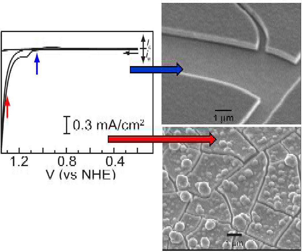
The Co-OEC forms in situ upon controlled potential electrolysis of Co2+ salts in pH 7 phosphate (Pi), methylphosphonate (MePi) or borate (Bi) electrolytes.151,152 During this time, a dark green-black film forms on the surface of the electrode surface. The catalyst deposits on a diverse array of conductive substrates (e.g., metals, indium-tin-oxide (ITO), fluorinated-tin-oxide (FTO), etc.) and films with thicknesses of 1 – 3000 nm may be grown depending on the electrodeposition time. Extremely smooth catalytically active films form immediately following oxidation of Co2+ to Co3+ (see Figure 12). This potential is more similar to the Co3+/2+ couple for cobalt ion with hydroxo ligands as opposed to aqua ligands (E[Co(OH)2+/0] = 1.1 V vs NHE, E[Co(OH2)63+/2+] = 1.9 V vs NHE153). Roughened films are obtained if the potential is stepped into the catalytic wave. All film morphologies, smooth or roughened, are active catalysts. Dissolved cobalt is not needed for catalyst operation and catalyst films are stable under normal storage conditions. The mild aqueous electrodeposition conditions permit conformal catalyst layer to form on complicated architectures.
Figure 12.
Cyclic voltammogram of a aqueous solution containing 1 mM Co2+ and 0.1 M Pi electrolyte. SEM images are shown of catalyst films that form holding the electrode at the indicated pre-catalytic and catalytic potential.
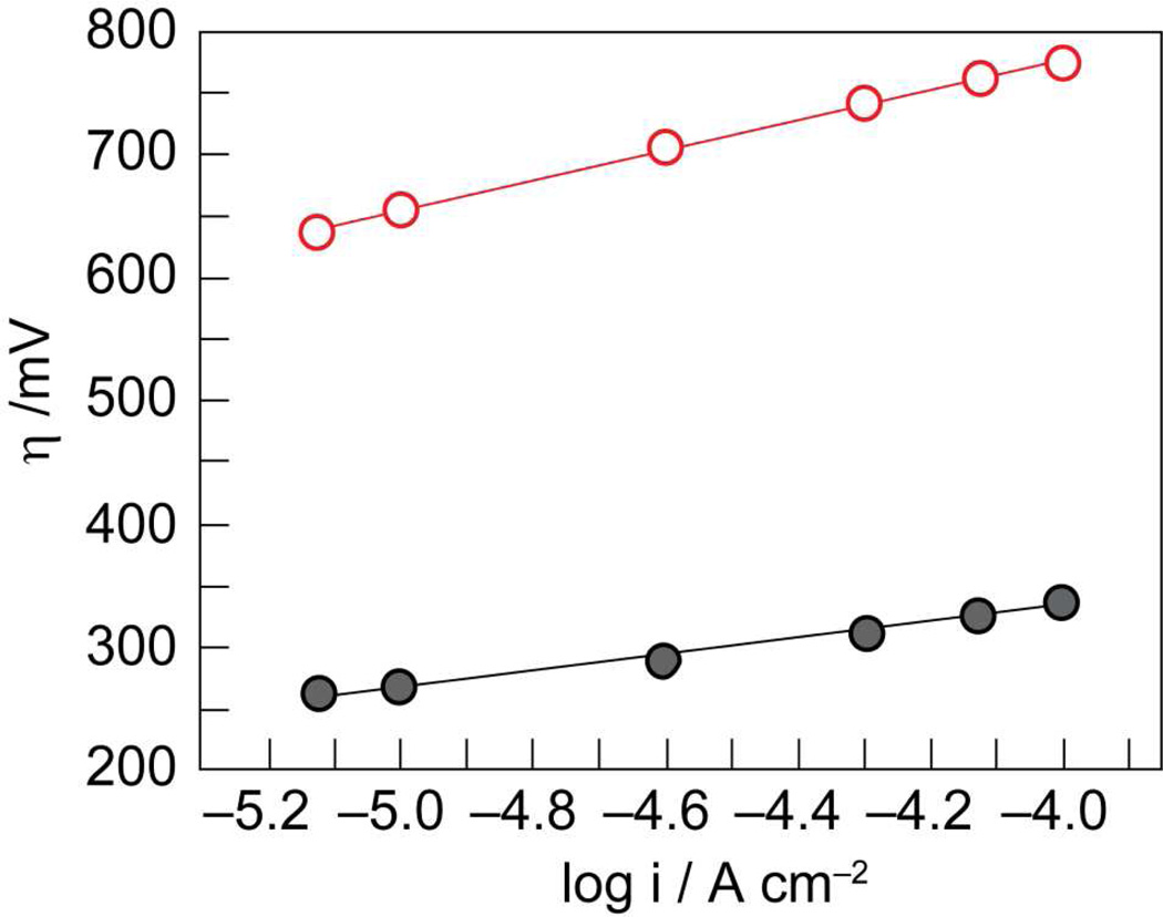
Co-OEC rivals or outperforms other water oxidation catalysts at neutral pH. The catalyst operates at 350 mV lower overpotential than Pt at all current densities at pH 7 (Figure 13). When operated at 10 mA/cm2, Co-OEC also outperforms expensive RuO2 anodes,154 widely considered to be a superior oxygen evolving catalyst.150 Moreover, the uniquely benign operating conditions translate into a new class of water splitting technologies that perform under safe conditions with low material and engineering costs. All-plastic composite electrolyzer cells have been constructed with cheap membranes and electrode materials. Current densities as large as 60 mA/cm2 have been achieved at 250 mV overpotential from neutral water at room temperature; current densities approaching 100 mA/cm2 have been observed from these plastic composite electrolyzer cells at temperatures operating at 60 °C.
Figure 13.
Tafel plots showing higher water oxidation activity of Co-OEC ( , gray) at lower overpotentials relative to Pt (
 , red) in aqueous solutions containing phosphate.
3.1.2. A Molecular Cubane
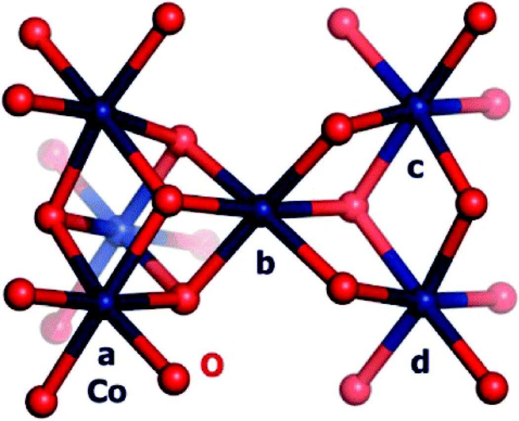
Extended X-ray absorption fine structure (EXAFS) and X-ray absorption near-edge structure (XANES) spectra have been measured on isolated Co-OEC films155 and Co-OEC films undergoing active catalysis.156 In its resting state, the film is primarily composed of Co3+ ions and a minority population of Co2+ ions. Upon the application of a potential, the appearance of Co4+ is evident in EPR and XANES spectra. Despite the presence of Co2+, Co3+ and Co4+, the EXAFS spectrum, which is identical for films in resting or active states, exhibits two prominent peaks at 1.89 Å for d(Co–O) and at 2.81 Å for d(Co–Co). The EXAFS spectrum is noticeably different than solid state oxides including Co3O4, CoO and CoO(OH), which exhibit prominent scattering features at longer distances (> 4 Å) owing to focusing effects arising from Co---Co---Co vectors in extended solids. Simulations of the EXAFS spectrum and analysis of model compounds reveal that the Co-OEC is composed of Co-oxo cubanes; nearest neighbor metal-metal interactions of 3.6 Å indicate that the presence of connected incomplete Co3(μ-O)4 or complete Co4(μ-O)4 dicubane units. The proposed structure of the catalyst in its resting state is shown in Figure 14.
Figure 14.
Proposed dicubane structure of the Co-OEC (cobalt in blue, oxygen in red) based on XAS experiments of ref 155. The Figure is reproduced from ref 155 with permission from the American Chemical Society.
3.1.3. A Self-Healing Catalyst
Non-noble metal-oxide catalysts corrode under benign conditions owing to the protons produced by water oxidation. In neutral water, the best base is the metal-oxide itself and consequently the very process of water splitting hastens catalyst corrosion. For the case of Co-OEC, the involvement of Co2+, Co3+ and Co4+ oxidation states during catalysis presents an additional challenge to the design of a robust catalyst. Co2+ is a high spin ion and is substitutionally labile whereas Co3+ and Co4+ are low spin and substitutionally inert in an oxygen-atom ligand field. As the propensity of metal ion dissolution from solid oxides has been shown to correlate with ligand substitution rates,157 Co-OEC is expected to be structurally unstable during turnover. Notwithstanding, Co-OEC is robust owing to its unique ability to undergo self-repair during turnover.158
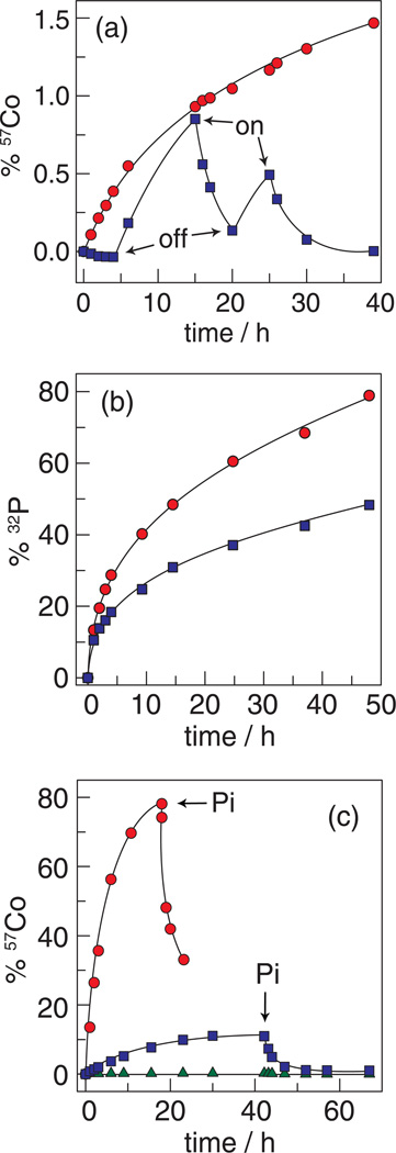
By monitoring radioactive isotopes of films composed of 57Co and 32P during water-splitting catalysis, we have shown that cobalt and phosphate are in a dynamic equilibrium during turnover. As shown in Figure 15a, any 57Co2+ released into solution during water-splitting catalysis is re-deposited upon its oxidation to Co3+ in the presence of phosphate. An equilibrium between Co3+ and Pi causes the cobalt cubane clusters to re-form during catalysis. This result accords well with the in situ formation of Co-OEC upon oxidation of Co2+ to Co3+ (vide infra). Figure 15b additionally shows that phosphate exchange is significantly greater than that of cobalt, as expected based on the molecular structure of the catalyst. Release of phosphate from a terminal ligation site should be much more facile than the release of a cobalt ion that is a constituent of a metal-oxo cubane core.
Figure 15.
Radioactive isotope tracer studies of the Co-OEC repair process. (a) Percentage of 57Co leached from films of Co-OEC on an electrode: with a potential bias of 1.3 V (NHE) turned on and off at the times designated ( ) (the trace begins with the applied potential on); and without an applied potential bias (
 ). (b) 32P leaching from Co-OEC on an electrode with an applied potential of 1.3 V (NHE) (
 ) and without an applied potential bias (
 ). (c) Percentage of 57Co leached from a typical Co-oxide catalyst on an electrode under a potential bias of 1.3 V (
 ) and 1.5 V (
 ) (NHE) and an unbiased electrode (
 ). Pi was added at the time points indicated by the arrows. Figures adapted from ref. 158 and reproduced here with permission from the American Chemical Society.
The “reversible corrosion” process permits long-term stability of the Co-OEC. Moreover, the repair mechanism can be used to “rescue” metals oxide catalysts that have corroded. As shown in Figure 15c, typical cobalt-oxide water splitting catalysts rapidly corrode under applied potentials that support water oxidation. The corrosion process is reversed immediately upon the addition of Pi and Co-OEC film forms as an overlayer to the corroding cobalt-oxide film. The current stabilizes and water splitting proceeds with the characteristics of the Co-OEC.
3.1.4. Water Splitting from Natural Water Sources
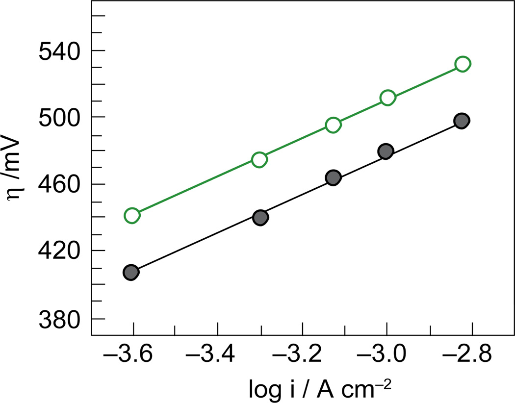
Co-OEC does not require pure water to function. This behavior is in contrast to catalysts in commercial electrolyzers, which require very high purity water as an input stream (typically to 18 MΩ). Oxygen production by Co-OEC from salt water (0.5 M Cl−) and sea water is accompanied by negligible levels of chlorine or hypochlorite.152 This is in contrast to typical metal-oxide water splitting catalysts, which promote Cl− oxidation in preference to water splitting. More recently, the Co-OEC has been shown to produce oxygen selectively from natural river streams. Figure 16 shows that the activity of Co-OEC in water from the Charles River passing in front of MIT parallels the activity of the catalyst in highly pure water with only a 40 mV offset. The efficient oxygen evolving ability of Co-OEC in sea and natural waters provides a significant technological advantage for the design of inexpensive electrolyzers interfaced to photovoltaic devices. We believe that the ability of Co-OEC to operate on natural water supplies is intimately connected to the repair mechanism. The catalyst does not foul because it breaks down and reforms during catalysis. Hence, a fresh catalyst surface is continually being presented during water splitting.
Figure 16.
Tafel plots for Co-OEC in 18 MΩ water ( , gray) and water collected from the Charles River in front of MIT (
 , green).
3.1.5. Photoelectrolysis
The generality and mildness of Co-OEC formation opens new avenues of exploration for solar fuels storage. Because water splitting is not performed in highly acidic or basic conditions, Co-OEC is amenable to integration with charge-separating networks comprising protein,159 organic and inorganic160–162 constituents. In these systems, the one-photon, one-electron charge separation can be accumulated by the catalyst to attain the four equivalents needed for water splitting. The benefits of this approach have already been demonstrated for direct light-to-fuel conversion by forming Co-OEC on inexpensive light harvesting anodes of a photoelectrochemical cell (PEC).163 Co-OEC formation on mesostructured α-Fe2O3 results in a >350 mV cathodic shift of the onset potential for PEC water oxidation and significantly higher incident-photon-to-current-efficiencies than observed for native α-Fe2O3. As demonstrated by this study, the ease of implementation of the Co-OEC with a diverse array of photoactive materials suggests that the catalyst will be of interest to many in their endeavors to store solar energy by water splitting.164
3.3. An Artificial Photosynthesis
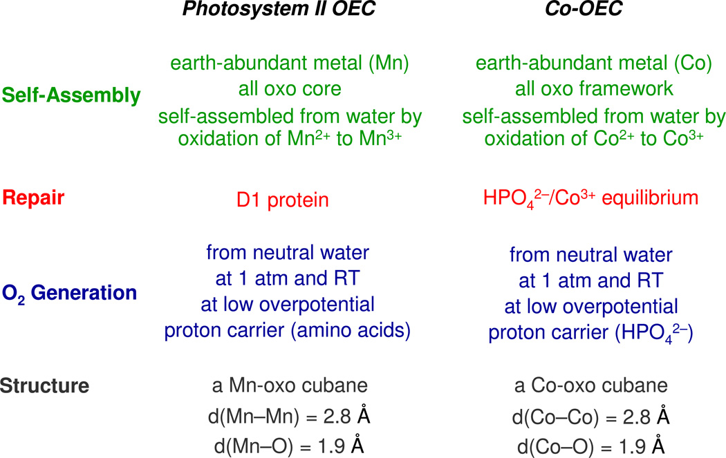
The Co-OEC captures many of the elements of the OEC of natural photosynthesis. Parallels between the two systems are highlighted in Chart 2.165 The photosynthetic OEC is a distorted manganese-calcium-oxo cubane166–169 that self-assembles upon the light-driven oxidation of Mn2+ to Mn3+ in aqueous solution.170 Similarly, the cobalt-oxo cubane of Co-OEC self-assembles upon the oxidation of Co2+ to Co3+ in aqueous solution. Water oxidation in the photosynthetic membrane proceeds under ambient environmental conditions as it does for Co-OEC. In photosynthesis, PCET at the OEC is bidirectional. Proton transfer occurs along water channels defined by amino acid side chains that establish a proton transfer pathway that is orthogonal to the electron transfer pathway to and from the OEC.171 For the Co-OEC, a bidirectional PCET is established with Pi (or MePi or Bi) in order to manage the protons for the PCET activation of the water molecules bound to the Co-OEC cubane. Oxygen production is harsh to the biological milieu and hence the OEC-protein complex is structurally unstable and a repair mechanism is required. Water oxidation at OEC produces reactive oxygen species, which damage the associated proteins of the PSII complex. Oxygenic photosynthetic organisms have evolved to replace the D1 protein in which the OEC resides with a newly synthesized copy every ~30 min.172 Thus functional stability is maintained despite structural instability. The same is true for the Co-OEC. Though the catalyst is inherently unstable, a small overpotential enables the establishment of an equilibrium between Co3+ and Pi (MePi or Bi) that reverses the corrosion process specific to Co2+ ion. Despite the structural instability of Co-OEC, function is preserved and oxygen is produced at a steady and reproducible rate.
Chart 2.
Comparison of functional properties of the Photosystem II OEC (Oxygen Evolving Complex) and the Co-OEC water-splitting catalyst.
Finally, the structural similarity of Co-OEC and the natural OEC is striking. Both water-splitting catalysts show only two prominent peaks in the EXAFS spectrum at 1.8 Å and 2.8 Å for the metal-oxo and metal-metal distances, respectively. On the basis of this structural similarity and the relationship between Co-OEC and OEC listed in Chart 2, one may ask whether Co could be accommodated in the OEC of a photosynthetic organism. Metal uptake experiments into higher order plants involving a variety of metals including cobalt have previously been attempted to no avail;173 only manganese was observed to be taken into the OEC of Photosystem II. But metal uptake involving Co should be performed under low light (LL) conditions. Photosynthetic organisms are known to down regulate metabolism under high light (HL) conditions owing to a variety of factors including oxygen toxicity.174–176 In view of the high water splitting activity of the Co cubane, it is not surprising that cobalt is toxic to the plant under HL conditions. But would the same result be observed funder LL conditions? More precisely, could photosynthetic organisms that exist under LL conditions, such as deep sea algae,177 take advantage of a highly active OEC that is non-manganese based? It is intriguing to note that some photosynthetic organisms that exist under LL conditions have an absolute cobalt requirement.178 Whereas the organisms have cobalt-based cofactors (e.g., vitamin B12), calculations of quotas suggest that a significant cobalt equivalency is unaccounted for by the presence of the cofactors.179,180 These observations together with the structural similarity of Co and Mn cubanes point to the fascinating possibility that cobalt may be taken up into the OEC active site of photosynthetic organisms adapted for LL levels. Even if Co is not used naturally, LL photosynthetic organisms may be promiscuous in accepting Co (and other first row metals such as Ni) into their OEC, depending on external environmental conditions of light level, temperature and nutrient availability. Such a possibility would not only be invaluable for design of photosynthetic organisms for bioenergy but could also be important to understanding how global environmental changes may affect carbon cycling.
4. Concluding Remarks
Personalized energy is transformative in its scope to achieve a secure energy future, to provide economic equity to people of the non-legacy world and to stem the flow of non-anthropogenic sources of CO2 into our environment. However, down-scaling current technologies to the personal level will not be economically feasible. Most energy systems are incommensurate with the very nature of PE because they have been designed to operate at large scale and high efficiency, and thus significant costs are associated with the balance of system on a small scale. Hence, the solution to solar PE will be one that begins with a blank sheet on which the discovery of PE will be written. New materials, new reactions and new processes such as those afforded by Co-OEC are needed to permit PE to be an attractive economic alternative. If the cost of solar PE through discovery can be decreased, then the development of the non-legacy world can occur within an energy infrastructure that is of the future and not the past. Considering that it is the 6 billion non-legacy users that are driving the enormous increase in energy demand by mid-century, a research target of solar PE provides the global society its most direct path to providing a solution for its sustainable energy future.
Acknowledgment
D.G.N. is indebted to the many students and co-workers who have performed the research described herein. He also acknowledges the NSF and NIH for long term support of his fundamental research and the AFOSR, ARO and DOE for supporting research of targeted interest. Finally, D.G.N. acknowledges the Chesonis Family Foundation for their long term vision and support of basic science that addresses important challenges confronting our societal future.
References
- 1.Hoffert MI, Caldeira K, Jain AK, Haites EF, Harvey LDD, Potter SD, Schlesinger ME, Schneider SH, Watts RG, Wigley TML, Wuebbles DJ. Nature. 1998;395:881. [Google Scholar]
- 2.Nocera DG. Daedalus. 2006;135:112. [Google Scholar]
- 3.Lewis NS, Nocera DG. Proc. Natl. Acad. Sci. U.S.A. 2006;103:15729. doi: 10.1073/pnas.0603395103. [DOI] [PMC free article] [PubMed] [Google Scholar]
- 4.Eisenberg R, Nocera DG. Inorg. Chem. 2005;44:6799. doi: 10.1021/ic058006i. [DOI] [PubMed] [Google Scholar]
- 5.Nocera DG. ChemSusChem. 2009;2:387. doi: 10.1002/cssc.200900040. [DOI] [PubMed] [Google Scholar]
- 6.Nocera DG. Chem. Soc. Rev. 2009;38:13. doi: 10.1039/b820660k. [DOI] [PubMed] [Google Scholar]
- 7.Owens BB, Smyrl WH, Xu JJ. J. Power Sources. 1999:81–82. 150. [Google Scholar]
- 8.Dempsey JL, Esswein AJ, Manke DR, Rosenthal J, Soper JD, Nocera DG. Inorg. Chem. 2005;44:6879. doi: 10.1021/ic0509276. [DOI] [PubMed] [Google Scholar]
- 9.Rosenthal J, Bachman J, Dempsey JL, Esswein AJ, Gray TG, Hodgkiss JM, Manke DR, Luckett TD, Pistorio BJ, Veige AS, Nocera DG. Coord. Chem. Rev. 2005;249:1316. [Google Scholar]
- 10.Kalyanasundaram K, Grätzel M, editors. Photosensitization and Photocatalysis Using Inorganic and Organometallic Compounds; Catalysis by Metal Complexes. Vol. 14. Dordrecht: Kluwer Academic; 1993. p. 247. [Google Scholar]
- 11.Balzani V, Barigelletti F, Decola L. Top. Curr. Chem. 1990;158:31. [Google Scholar]
- 12.Amouyal E. In: Homogeneous Photocatalysis. Chanon M, editor. New York: Wiley; 1997. p. 263. [Google Scholar]
- 13.Sutin N, Creutz C, Fujita E. Comm. Inorg. Chem. A. 1997;19:67. [Google Scholar]
- 14.Bard AJ, Fox MA. Acc. Chem. Res. 1995;28:141. [Google Scholar]
- 15.Schoonover JR, Bignozzi CA, Meyer TJ. Coord. Chem. Rev. 1997;165:239. [Google Scholar]
- 16.Krausz E, Ferguson J. Prog. Inorg. Chem. 1989;37:293. [Google Scholar]
- 17.Juris A, Balzani V, Barigelletti F, Campagna S, Belser P, von Zelewsky A. Coord. Chem. Rev. 1988;84:85. [Google Scholar]
- 18.Kalyanasundaram K. Photochemistry of Polypyridine and Porphyrin Complexes. London: Academic Press; 1982. Ch 6. [Google Scholar]
- 19.Crosby GL. Acc. Chem. Res. 1975;8:231. [Google Scholar]
- 20.Rothberg LJ, Cooper NJ, Peters KS, Vaida V. J. Am. Chem. Soc. 1982;104:3536. [Google Scholar]
- 21.Zhang JZ, Harris CB. J. Chem. Phys. 1991;95:4024. [Google Scholar]
- 22.Kim SK, Pedersen S, Zewail AH. Chem. Phys. Lett. 1995;233:500. [Google Scholar]
- 23.Roundhill DM, Gray HB, Che CM. Acc. Chem. Res. 1989;22:55. [Google Scholar]
- 24.Fordyce WA, Brummer JG, Crosby GA. J. Am. Chem. Soc. 1981;103:7061. [Google Scholar]
- 25.Geoffrey GL, Wrighton MS. Organometallic Photochemistry. New York: Academic Press; 1979. [Google Scholar]
- 26.Heitler W, London F. Z. f. Phys. 1927;44:455. [Google Scholar]
- 27.Pauling L. Chem. Rev. 1928;5:173. [Google Scholar]
- 28.Mulliken RS. Phys. Rev. 1928;32:186. [Google Scholar]
- 29.Coulson CA, Fischer I. Philos. Mag. 1949;40:386. [Google Scholar]
- 30.Even here, inorganic chemistry has made the unimaginable a reality. A “stretched” π-bond has been isolated in a stabilized configuration by using Hg2+ ion to juxtapose two Mo(silox)2NtBu cores at long distance. See Rosenfeld DC, Wolczanski PT, Barakat KA, Buda C, Cundari TR. J. Am. Chem. Soc. 2005;127:8262. doi: 10.1021/ja051070e.
- 31.Cotton FA, Nocera DG. Acc. Chem. Res. 2000;33:483. doi: 10.1021/ar980116o. [DOI] [PubMed] [Google Scholar]
- 32.Figgis BM, Martin RL. J. Chem. Soc. 1956:3837. [Google Scholar]
- 33.Ross IG. Trans. Faraday Soc. 1959;55:1057. [Google Scholar]
- 34.Cotton FA, Curtis NF, Harris CB, Johnson BFG, Lippard SJ, Mague JT, Robinson WR, Wood JS. Science. 1964;145:1305. doi: 10.1126/science.145.3638.1305. [DOI] [PubMed] [Google Scholar]
- 35.Cowman CD, Gray HB. J. Am. Chem. Soc. 1973;95:8177. [Google Scholar]
- 36.Hay PJ. J. Am. Chem. Soc. 1982;104:7007. [Google Scholar]
- 37.Hopkins MD, Zietlow TC, Miskowski VM, Gray HB. J. Am. Chem. Soc. 1985;107:510. [Google Scholar]
- 38.Cotton FA, Eglin JL, Hong B, James CA. J. Am. Chem. Soc. 1992;114:4915. [Google Scholar]
- 39.Engebretson DS, Zaleski JM, Leroi GE, Nocera DG. Science. 1994;265:759. doi: 10.1126/science.265.5173.759. [DOI] [PubMed] [Google Scholar]
- 40.Engebretson DS, Graj EM, Leroi GE, Nocera DG. J. Am. Chem. Soc. 1999;121:868. [Google Scholar]
- 41.Hopkins MD, Gray HB, Miskowski VM. Polyhedron. 1987;6:705. [Google Scholar]
- 42.Hsu TLC, Helvoigt SA, Partigianoni CM, Turró C, Nocera DG. Inorg. Chem. 1995;34:6186. [Google Scholar]
- 43.Partigianoni CM, Turró C, Hsu TLC, Chang I-J, Nocera DG. In: Photosensitive Metal-Organic Systems; Mechanistic Principles and Applications; Adv. Chem. Ser. 238. Kutal C, Serpone N, editors. Washington, D.C.: American Chemical Society; 1993. p. 147. [Google Scholar]
- 44.Partigianoni CM, Nocera DG. Inorg. Chem. 1990;29:2033. [Google Scholar]
- 45.Pistorio BJ, Nocera DG. Chem. Commun. 1999:1831. [Google Scholar]
- 46.Taube H. Angew. Chem. Int. Ed. Engl. 1984;23:329. [Google Scholar]
- 47.Creutz C. Prog. Inorg. Chem. 1983;30:1. [Google Scholar]
- 48.Prassides K, editor. Mixed Valency System: Applications in Chemistry, Physics and Biology; NATO ASI Series C: Mathematical and Physical Sciences 343. Dordrecht: Kluwer Academic; 1991. [Google Scholar]
- 49.Schatz PN. In: Inorganic Electronic Structure and Spectroscopy. Solomon EI, Lever ABP, editors. Vol. 2. New York: Wiley-Interscience; 1999. p. 175. [Google Scholar]
- 50.Ito T, Hamaguchi T, Nagino H, Yamaguchi T, Kido H, Zavarine IS, Richmond T, Washington J, Kubiak CP. J. Am. Chem. Soc. 1999;121:4625. [Google Scholar]
- 51.Ito T, Hamaguchi T, Nagino H, Yamaguchi T, Washington J, Kubiak CP. Science. 1997;277:660. [Google Scholar]
- 52.Vahrenkamp H, Geiss A, Richardson GN. J. Chem. Soc. Dalton Trans. 1997:3643. [Google Scholar]
- 53.Balzani V, Juris A, Venturi M, Campagna S, Serroni S. Chem. Rev. 1996;96:759. doi: 10.1021/cr941154y. [DOI] [PubMed] [Google Scholar]
- 54.Kunkely H, Pawlowski V, Vogler A. Inorg. Chim. Acta. 1994;225:327. [Google Scholar]
- 55.Vogler A, Osman AH, Kunkely H. Coord. Chem. Rev. 1985;64:159. [Google Scholar]
- 56.Nocera DG. Acc. Chem. Res. 1995;28:209. [Google Scholar]
- 57.Heyduk AF, Macintosh AM, Nocera DG. J. Am. Chem. Soc. 1999;121:5023. [Google Scholar]
- 58.Odom AL, Heyduk AF, Nocera DG. Inorg. Chim. Acta. 2000;297:330. [Google Scholar]
- 59.Heyduk AF, Nocera DG. J. Am. Chem. Soc. 2000;122:9415. [Google Scholar]
- 60.Heyduk AF, Nocera DG. Chem. Commun. 1999:1519. [Google Scholar]
- 61.Veige AS, Nocera DG. Chem. Commun. 2004:1958. doi: 10.1039/b402426e. [DOI] [PubMed] [Google Scholar]
- 62.Manke DR, Loh ZH, Nocera DG. Inorg. Chem. 2004;43:3618. doi: 10.1021/ic049795r. [DOI] [PubMed] [Google Scholar]
- 63.Manke DR, Nocera DG. Inorg. Chem. 2003;42:4431. doi: 10.1021/ic0340478. [DOI] [PubMed] [Google Scholar]
- 64.Manke DR, Nocera DG. Inorg. Chim. Acta. 2003;345:235. [Google Scholar]
- 65.Gray TG, Nocera DG. Chem. Commun. 2005:1540. doi: 10.1039/b410003d. [DOI] [PubMed] [Google Scholar]
- 66.Esswein AJ, Veige AS, Nocera DG. Organometallics. 2008;27:1073. [Google Scholar]
- 67.Veige AS, Gray TG, Nocera DG. Inorg. Chem. 2005;44:17. doi: 10.1021/ic049246l. [DOI] [PubMed] [Google Scholar]
- 68.Gray TG, Veige AS, Nocera DG. J. Am. Chem. Soc. 2004;126:9760. doi: 10.1021/ja0491432. [DOI] [PubMed] [Google Scholar]
- 69.Norton JR. Acc. Chem. Res. 1979;12:139. [Google Scholar]
- 70.Martin BD, Warner KE, Norton JE. J. Am. Chem. Soc. 1986;108:33. [Google Scholar]
- 71.Kristjánsdóttir SS, Norton JA. Ch. 9. In: Dedieu A, editor. Transition Metal Hydrides. New York: VCH; 1992. p. 309. [Google Scholar]
- 72.Floriani C, Floriani-Moro R. Ch. 25. In: Kadish K, Smith KM, Guilard R, editors. The Porphyrin Handbook. Vol. 3. San Diego CA: Academic Press; 2000. p. 405. [Google Scholar]
- 73.De Angelis S, Solari E, Floriani C, Chiesi-Villa A, Rizzoli C. J. Am. Chem. Soc. 1994;116:5691. [Google Scholar]
- 74.De Angelis S, Solari E, Floriani C, Chies-Villa A, Rizzoli C. J. Am. Chem. Soc. 1994;116:5702. [Google Scholar]
- 75.Crescenzi R, Solari E, Floriani C, Chiesi-Villa A, Rizzoli C. J. Am. Chem. Soc. 1999;121:1695. [Google Scholar]
- 76.Bachmann J, Nocera DG. Inorg. Chem. 2005;44:6930. doi: 10.1021/ic0511017. [DOI] [PubMed] [Google Scholar]
- 77.Bachmann J, Nocera DG. J. Am. Chem. Soc. 2004;126:2829. doi: 10.1021/ja039617h. [DOI] [PubMed] [Google Scholar]
- 78.Bachmann J, Nocera DG. J. Am. Chem. Soc. 2005;127:4730. doi: 10.1021/ja043132r. [DOI] [PubMed] [Google Scholar]
- 79.Bachmann J, Hodgkiss JM, Young ER, Nocera DG. Inorg. Chem. 2007;46:607. doi: 10.1021/ic0616636. [DOI] [PubMed] [Google Scholar]
- 80.Bachmann J, Teets TS, Nocera DG. Dalton Trans. 2008:4549. doi: 10.1039/b809366k. [DOI] [PubMed] [Google Scholar]
- 81.Esswein AJ, Nocera DG. Chem. Rev. 2007;107:4022. doi: 10.1021/cr050193e. [DOI] [PubMed] [Google Scholar]
- 82.Heyduk AF, Nocera DG. Science. 2001;293:1639. doi: 10.1126/science.1062965. [DOI] [PubMed] [Google Scholar]
- 83.Esswein AJ, Veige AS, Nocera DG. J. Am. Chem. Soc. 2005;127:16641. doi: 10.1021/ja054371x. [DOI] [PubMed] [Google Scholar]
- 84.Esswein AJ, Dempsey JL, Nocera DG. Inorg. Chem. 2007;46:2362. doi: 10.1021/ic062203f. [DOI] [PubMed] [Google Scholar]
- 85.Cook TR, Esswein AJ, Nocera DG. J. Am. Chem. Soc. 2007;129:10094. doi: 10.1021/ja073908z. [DOI] [PubMed] [Google Scholar]
- 86.Cook TR, Surendranath Y, Nocera DG. J. Am. Chem. Soc. 2009;131:28. doi: 10.1021/ja807222p. [DOI] [PubMed] [Google Scholar]
- 87.Teets TS, Nocera DG. J. Am. Chem. Soc. 2009;131:7411. doi: 10.1021/ja9009937. [DOI] [PubMed] [Google Scholar]
- 88.Kadis J, Shin Y-gS, Dulebohn JI, Ward DL, Nocera DG. Inorg. Chem. 1996;35:811. doi: 10.1021/ic9505615. [DOI] [PubMed] [Google Scholar]
- 89.Ronco S, Ferraudi G. Excited State Redox Reactions of Transition Metal Complexes. In: Nalwa HS, editor. Handbook of Photochemistry and Photobiology. Stevenson Ranch, CA: American Scientific Publishers; 2003. p. 283. [Google Scholar]
- 90.Pourbaix M. Atlas of Electrochemical Equilibria in Aqueous Solutions. Oxford: Pergamon Press; 1966. [Google Scholar]
- 91.Klinman JP. Phil. Trans. Roy. Soc. B. 2006;361:1323. doi: 10.1098/rstb.2006.1870. [DOI] [PMC free article] [PubMed] [Google Scholar]
- 92.Kohen A, Klinman JP. Acc. Chem. Res. 1998;31:397. [Google Scholar]
- 93.Wiberg KB. Chem. Rev. 1955;55:713. [Google Scholar]
- 94.Westheimer FH. Chem. Rev. 1961;61:265. [Google Scholar]
- 95.Scheppele SE. Chem. Rev. 1972;72:511. [Google Scholar]
- 96.Mayer JM. Annu. Rev. Phys. Chem. 2004;55:363. doi: 10.1146/annurev.physchem.55.091602.094446. [DOI] [PubMed] [Google Scholar]
- 97.Huynh MHV, Meyer TJ. Chem. Rev. 2007;107:5004. doi: 10.1021/cr0500030. [DOI] [PMC free article] [PubMed] [Google Scholar]
- 98.Chang CJ, Brown JDK, Chang MCY, Baker EA, Nocera DG. In: Electron Transfer in Chemistry. Balzani V, editor. vol. 3.2.4. Weinheim, Germany: Wiley-VCH; 2001. p. 409. [Google Scholar]
- 99.Stubbe J, Nocera DG, Yee CS, Chang MCY. Chem. Rev. 2003;103:2167. doi: 10.1021/cr020421u. [DOI] [PubMed] [Google Scholar]
- 100.Chang CJ, Chang MCY, Damrauer NH, Nocera DG. Biophys. Biochim. Acta. 2004;1655:13. doi: 10.1016/j.bbabio.2003.08.010. [DOI] [PubMed] [Google Scholar]
- 101.Cukier RI, Nocera DG. Annu. Rev. Phys. Chem. 1998;49:337. doi: 10.1146/annurev.physchem.49.1.337. [DOI] [PubMed] [Google Scholar]
- 102.Hammes-Schiffer S. Acc. Chem. Res. 2001;34:273. doi: 10.1021/ar9901117. [DOI] [PubMed] [Google Scholar]
- 103.Turró C, Chang CK, Leroi GE, Cukier RI, Nocera DG. J. Am. Chem. Soc. 1992;114:4013. [Google Scholar]
- 104.Yeh CY, Miller SE, Carpenter SD, Nocera DG. Inorg. Chem. 2001;40:3643. doi: 10.1021/ic001387+. [DOI] [PubMed] [Google Scholar]
- 105.Damrauer NH, Hodgkiss JM, Rosenthal J, Nocera DG. J. Phys. Chem. B. 2004;108:6315. doi: 10.1021/jp049296b. [DOI] [PubMed] [Google Scholar]
- 106.Roberts JA, Kirby JP, Nocera DG. J. Am. Chem. Soc. 1995;117:8051. [Google Scholar]
- 107.Roberts JA, Kirby JP, Wall ST, Nocera DG. Inorg. Chim. Acta. 1997;263:395. [Google Scholar]
- 108.Deng Y, Roberts JA, Peng SM, Chang CK, Nocera DG. Angew. Chem. Int. Ed. Engl. 1997;36:2124. [Google Scholar]
- 109.Kirby JP, Roberts JA, Nocera DG. J. Am. Chem. Soc. 1997;119:9230. [Google Scholar]
- 110.Kirby JP, van Dantzig NA, Chang CK, Nocera DG. Tetrahedron Lett. 1995;36:3477. [Google Scholar]
- 111.Rosenthal J, Young ER, Nocera DG. Inorg. Chem. 2007;46:8668. doi: 10.1021/ic700838s. [DOI] [PubMed] [Google Scholar]
- 112.Rosenthal J, Hodgkiss JM, Young ER, Nocera DG. J. Am. Chem. Soc. 2006;128:10474. doi: 10.1021/ja062430g. [DOI] [PubMed] [Google Scholar]
- 113.Young ER, Rosenthal J, Nocera DG. Chem. Commun. 2008:2322. doi: 10.1039/b717747j. [DOI] [PMC free article] [PubMed] [Google Scholar]
- 114.Young ER, Rosenthal J, Hodgkiss JM, Nocera DG. J. Am. Chem. Soc. 2009;131:7678. doi: 10.1021/ja809777j. [DOI] [PMC free article] [PubMed] [Google Scholar]
- 115.Hodgkiss JM, Damrauer NH, Pressé S, Rosenthal J, Nocera DG. J. Phys. Chem. B. 2006;110:18853. doi: 10.1021/jp056703q. [DOI] [PubMed] [Google Scholar]
- 116.Hodgkiss JM, Rosenthal J, Nocera DG. In: Handbook of Hydrogen Transfer. Physical and Chemical Aspects of Hydrogen Transfer. Hynes JT, Klinman JP, Limbach H-H, Schowen RL, editors. vol. 2.4.17. Weinheim, Germany: Wiley-VCH; 2006. p. 503. [Google Scholar]
- 117.Hammes-Schiffer S. Acc. Chem. Res. 2006;39:93. doi: 10.1021/ar040199a. [DOI] [PubMed] [Google Scholar]
- 118.Reece SY, Nocera DG. In: Quantum Tunneling in Enzyme Catalyzed Reactions. Scrutton N, Allemann R, editors. London: Royal Society of Chemistry Press; 2009. [Google Scholar]
- 119.Reece SY, Hodgkiss JM, Stubbe J, Nocera DG. Phil. Trans. Royal Soc. B. 2006;361:1351. doi: 10.1098/rstb.2006.1874. [DOI] [PMC free article] [PubMed] [Google Scholar]
- 120.Reece SY, Nocera DG. Annu. Rev. Biochem. 2009;78:673. doi: 10.1146/annurev.biochem.78.080207.092132. [DOI] [PMC free article] [PubMed] [Google Scholar]
- 121.Yeh CY, Chang CJ, Nocera DG. J. Am. Chem. Soc. 2001;123:1513. doi: 10.1021/ja003245k. [DOI] [PubMed] [Google Scholar]
- 122.Chang CJ, Chng LL, Nocera DG. J. Am. Chem. Soc. 2003;125:1866. doi: 10.1021/ja028548o. [DOI] [PubMed] [Google Scholar]
- 123.Chng LL, Chang CJ, Nocera DG. Org. Lett. 2003;5:2421. doi: 10.1021/ol034581j. [DOI] [PubMed] [Google Scholar]
- 124.Chang CJ, Yeh CY, Nocera DG. J. Org. Chem. 2002;67:1403. doi: 10.1021/jo016095k. [DOI] [PubMed] [Google Scholar]
- 125.Liu SY, Nocera DG. J. Am. Chem. Soc. 2005;127:5278. doi: 10.1021/ja042849b. [DOI] [PubMed] [Google Scholar]
- 126.Yang JY, Bachmann J, Nocera DG. J. Org. Chem. 2006;71:8706. doi: 10.1021/jo0613075. [DOI] [PubMed] [Google Scholar]
- 127.Yang JY, Nocera DG. Tetrahedron Lett. 2008;49:4796. [Google Scholar]
- 128.Hodgkiss JM, Krivokapic A, Nocera DG. J. Phys. Chem. B. 2007;111:8258. doi: 10.1021/jp070447v. [DOI] [PubMed] [Google Scholar]
- 129.Yang JY, Nocera DG. J. Am. Chem. Soc. 2007;129:8192. doi: 10.1021/ja070358w. [DOI] [PubMed] [Google Scholar]
- 130.Chang CJ, Chng LL, Nocera DG. J. Am. Chem. Soc. 2003;125:1866. doi: 10.1021/ja028548o. [DOI] [PubMed] [Google Scholar]
- 131.Chng LL, Chang CJ, Nocera DG. Org. Lett. 2003;5:2421. doi: 10.1021/ol034581j. [DOI] [PubMed] [Google Scholar]
- 132.Rosenthal J, Chng LL, Fried SD, Nocera DG. Chem. Commun. 2007:2642. doi: 10.1039/b616884a. [DOI] [PubMed] [Google Scholar]
- 133.Liu SY, Nocera DG. Tetrahedron Lett. 2006;47:1923. [Google Scholar]
- 134.Yang JY, Nocera DG. ChemSusChem. 2008;1:941. doi: 10.1002/cssc.200800099. [DOI] [PubMed] [Google Scholar]
- 135.Rosenthal J, Nocera DG. Acc. Chem. Res. 2007;40:543. doi: 10.1021/ar7000638. [DOI] [PubMed] [Google Scholar]
- 136.Rosenthal J, Nocera DG. Prog. Inorg. Chem. 2007;55:483. [Google Scholar]
- 137.Liu SY, Soper JD, Yang JY, Rybak-Akimova EV, Nocera DG. Inorg. Chem. 2006;45:7572. doi: 10.1021/ic0602087. [DOI] [PubMed] [Google Scholar]
- 138.Soper JD, Kryatov SV, Rybak-Akimova EV, Nocera DG. J. Am. Chem. Soc. 2007;129:5069. doi: 10.1021/ja0683032. [DOI] [PubMed] [Google Scholar]
- 139.Betley TA, Wu Q, Voorhis TV, Nocera DG. Inorg. Chem. 2008;47:1849. doi: 10.1021/ic701972n. [DOI] [PubMed] [Google Scholar]
- 140.Betley TA, Surendranath Y, Childress MV, Alliger GE, Fu R, Cummins CC, Nocera DG. Phil. Trans. Royal Soc. B. 2008;363:1293. doi: 10.1098/rstb.2007.2226. [DOI] [PMC free article] [PubMed] [Google Scholar]
- 141.Chang CJ, Loh ZH, Shi C, Anson FC, Nocera DG. J. Am. Chem. Soc. 2004;126:10013. doi: 10.1021/ja049115j. [DOI] [PubMed] [Google Scholar]
- 142.Barber J. Phil. Trans. Roy. Soc. A. 2007;365:1007. doi: 10.1098/rsta.2006.1962. [DOI] [PubMed] [Google Scholar]
- 143.Barber J. Inorg. Chem. 2008;47:1700. doi: 10.1021/ic701835r. [DOI] [PubMed] [Google Scholar]
- 144.Eisenberg R, Gray HB. Inorg. Chem. 2008;47:1697. doi: 10.1021/ic800155g. [DOI] [PubMed] [Google Scholar]
- 145.Seyedsayamdost MR, Yee CS, Reece SY, Nocera DG, Stubbe J. J. Am. Chem. Soc. 2006;128:1562. doi: 10.1021/ja055927j. [DOI] [PubMed] [Google Scholar]
- 146.Seyedsayamdost MR, Reece SY, Nocera DG, Stubbe J. J. Am. Chem. Soc. 2006;128:1569. doi: 10.1021/ja055926r. [DOI] [PubMed] [Google Scholar]
- 147.Reece SY, Nocera DG. J. Am. Chem. Soc. 2005;127:9448. doi: 10.1021/ja0510360. [DOI] [PubMed] [Google Scholar]
- 148.Irebo T, Reece SY, Sjödin M, Nocera DG, Hammarström L. J. Am. Chem. Soc. 2007;129:154622. doi: 10.1021/ja073012u. [DOI] [PubMed] [Google Scholar]
- 149.Ishikita H, Soudackov AV, Hammes-Schiffer S. J. Am. Chem. Soc. 2007;129:11146. doi: 10.1021/ja072708k. [DOI] [PubMed] [Google Scholar]
- 150.Lipkowski J, Philip N, Ross PN, editors. Frontiers of Electrochemistry. Vol. 3. New York: VCH; 1994. The Electrochemistry of Novel Materials. and references therein. [Google Scholar]
- 151.Kanan MW, Nocera DG. Science. 2008;321:1072. doi: 10.1126/science.1162018. [DOI] [PubMed] [Google Scholar]
- 152.Surendranath Y, Dincă M, Nocera DG. J. Am. Chem. Soc. 2009;131:2615. doi: 10.1021/ja807769r. [DOI] [PubMed] [Google Scholar]
- 153.Brunschwig BS, Chou MH, Creutz C, Ghosh P, Sutin N. J. Am. Chem. Soc. 1983;105:4832. [Google Scholar]
- 154.Burke LD, Murphy OJ, O’Neill JF, Venkatesan S. J. Chem. Soc. Faraday I. 1977;73:1659. [Google Scholar]
- 155.Risch M, Khare V, Zaharieva I, Gerencser L, Chernev P, Dau H. J. Am. Chem. Soc. 2009;131:6936. doi: 10.1021/ja902121f. [DOI] [PubMed] [Google Scholar]
- 156.Kanan MW, Surendranath Y, Dincă M, Yano J, Yachandra VK, Nocera DG. doi: 10.1021/ja1023767. to be published. [DOI] [PubMed] [Google Scholar]
- 157.Casey WH. J. Coll. Inter. Sci. 1991;146:586. [Google Scholar]
- 158.Lutterman DA, Surendranath Y, Nocera DG. J. Am. Chem. Soc. 2009;131:3838. doi: 10.1021/ja900023k. [DOI] [PubMed] [Google Scholar]
- 159.Shih C, Museth AK, Abrahamsson M, Blanco-Rodriguez AM, Di Bilio AJ, Sudhamsu J, Crane BR, Ronayne KL, Towrie M, Vlcek A, Jr, Richards JH, Winkler JR, Gray HB. Science. 2008;320:1760. doi: 10.1126/science.1158241. [DOI] [PubMed] [Google Scholar]
- 160.Fukuzumi S. Phys. Chem. Chem. Phys. 2008;10:2283. doi: 10.1039/b801198m. [DOI] [PubMed] [Google Scholar]
- 161.Hambourger M, Moore GF, Kramer DM, Gust D, Moore AL, Moore TA. Chem. Soc. Rev. 2009;38:25. doi: 10.1039/b800582f. [DOI] [PubMed] [Google Scholar]
- 162.Flamigni L, Collin JP, Sauvage JP. Acc. Chem. Res. 2008;41:857. doi: 10.1021/ar700282n. [DOI] [PubMed] [Google Scholar]
- 163.Zhong DK, Sun J, Inumaru H, Gamelin DR. J. Am. Chem. Soc. 2009;131:6086. doi: 10.1021/ja9016478. [DOI] [PubMed] [Google Scholar]
- 164.Turner J. Nature Mat. 2008;7:770. doi: 10.1038/nmat2284. [DOI] [PubMed] [Google Scholar]
- 165.Kanan MW, Surendranath Y, Nocera DG. Chem. Soc. Rev. 2009;38:109. doi: 10.1039/b802885k. [DOI] [PubMed] [Google Scholar]
- 166.Ferreira KN, Iverson TM, Maghlaoui K, Barber J, Iwata S. Science. 2004;303:1831. doi: 10.1126/science.1093087. [DOI] [PubMed] [Google Scholar]
- 167.Loll B, Kern J, Saenger W, Zoun A, Biesiadka J. Nature. 2005;438:1040. doi: 10.1038/nature04224. [DOI] [PubMed] [Google Scholar]
- 168.Yano J, Kern J, Sauer K, Latimer MJ, Pushkar Y, Biesiadka J, Loll B, Saenger W, Messinger J, Zouni A, Yachandra VK. Science. 2006;314:821. doi: 10.1126/science.1128186. [DOI] [PMC free article] [PubMed] [Google Scholar]
- 169.Guskov A, Kern J, Gabdulkhakov A, Broser M, Zouni A, Saenger W. Nat. Struct. Mol. Biol. 2009;16:334. doi: 10.1038/nsmb.1559. [DOI] [PubMed] [Google Scholar]
- 170.Burnap RL. Phys. Chem. Chem. Phys. 2004;6:4803. [Google Scholar]
- 171.Murray JW, Barber J. J. Struct. Biol. 2007;159:228. doi: 10.1016/j.jsb.2007.01.016. [DOI] [PubMed] [Google Scholar]
- 172.Aro EM, Suorsa M, Rokka A, Allahverdiyeva Y, Paakkarinen V, Saleem A, Battchikova N, Rintamaki E. J. Exp. Bot. E. 2005;56:347. doi: 10.1093/jxb/eri041. [DOI] [PubMed] [Google Scholar]
- 173.Ananyev GM, Zaltsman L, Vasko C, Dismukes GC. Biochim. Biophys. Acta. 2001;1503:52. doi: 10.1016/s0005-2728(00)00215-2. [DOI] [PubMed] [Google Scholar]
- 174.Barber J, Andersson B. Tr. Biochem. Sci. 1992;17:61. doi: 10.1016/0968-0004(92)90503-2. [DOI] [PubMed] [Google Scholar]
- 175.Aro EM, Virgin I, Andersson B. Biochim. Biophys. Acta. 1993;1143:113. doi: 10.1016/0005-2728(93)90134-2. [DOI] [PubMed] [Google Scholar]
- 176.Long SP, Humphries S, Falkowski PG. Annu. Rev. Plant Physiol. 1994;45:633. [Google Scholar]
- 177.Coleman ML, Chisholm SW. Tr. Microbiol. 2007;15:398. doi: 10.1016/j.tim.2007.07.001. [DOI] [PubMed] [Google Scholar]
- 178.Saito MA, Moffett JW, Chisholm SW, Waterbury JB. Limnol. Oceanogr. 2002;47:1629. [Google Scholar]
- 179.Sunda WG, Huntsman SA. Limnol. Oceanogr. 1995;40:1404. [Google Scholar]
- 180.Wilhelm SW, Trick CG. Can. J. Microbiol. 1995;41:145. doi: 10.1139/m95-155. [DOI] [PubMed] [Google Scholar]


