Abstract
Facial asymmetries exist in all individuals. Due to these facial asymmetries that exist, a standardized approach in locating the occlusal plane that is parallel to the ala-tragus and interpupillary lines, may result in less than ideal esthetics in the final restoration. The challenge for the prosthodontist is to determine an acceptable occlusal plane with an individualized approach that can be used as a guide for alignment of the maxillary anterior teeth in cases that require their replacement or extensive restoration. The present study uses an inexpensive and standardized digital photographic technique along with computer assisted analysis to measure the asymmetries of the human face. Statistical Analysis used-Karl pearson’s correlation coeffient was used. The correlation coefficient was then subjected to ‘t’ test and ‘p’ value was used to find out the level of statistical significance. Left side of the face was found to be at a higher level than the right side.
Electronic supplementary material
The online version of this article (doi:10.1007/s13191-011-0087-4) contains supplementary material, which is available to authorized users.
Keywords: Facial asymmetry, Occlusal plane, Esthetics
Introduction
Perfect bilateral body symmetry is more of a theoretic concept that seldom exists in living organisms [1]. Biologic structures in vertebrates develop according to a general symmetric pattern, but during growth and development, the two halves modify their basic design and various degrees of asymmetry develop in different organs and features.
Structural asymmetry can further be modified by function, trauma or disease [2]. Thus, there are always asymmetries of the human face, even in those who have been judged to be “beautiful”. Due to these facial asymmetries that exist, a standardized approach in locating the occlusal plane that is parallel to the ala-tragus and interpupillary lines, may result in less than ideal esthetics in the final restoration. Hence, the challenge for the prosthodontist is to determine an acceptable occlusal plane with an individualized approach that can be used as a guide for alignment of the maxillary anterior teeth in cases that require their replacement or extensive restoration.
The present study uses an inexpensive and standardized digital photographic technique along with computer assisted analysis to measure the asymmetries of the human face.
Subject and Methods
In this study, one hundred subjects were randomly selected from the students of the college. All subjects were in the age group ranging between 20 and 26 years. There were 48 males and 52 females. All the selected subjects had a normal appearance with no obvious deformities. Subjects with history of orthodontic treatment, trauma and impacted or missing canines were excluded.
Photographic Technique
A small rectangular mirror was attached to the top of the camera such that the lower border of the mirror was horizontal.
The camera was placed on a standard adjustable tripod stand. The arms and adjustable plates of the tripod stand were set so that the camera was horizontal (Fig. 1).
Fig. 1.
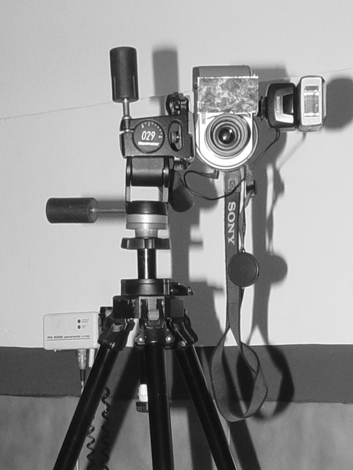
Set-up of the Camera
In this study, a Sony Mavica CD 300 digital camera was used which stores the photographs digitally that can be later transferred to the computer. The camera has a resolution of 3.3 Mega pixels, which is adequate for computer analysis. The inbuilt motorized zoom lens with an autofocus range to infinity ensured that the images were of high quality.
Positioning of the Subject
The subjects were asked to stand below the cephalostat machine on the footprints made on a foot mat. The footprints were at a comfortable distance apart with slight divergence. The ear posts of the cephalostat were then inserted into the subjects ears’ snugly to standardize the head position. The ear posts of the cephalostat being located at the same level, when inserted snugly into the external auditory meatus (EOM) of the subject, brought the EOM of both the right and left sides to the same horizontal level (Fig. 2).
Fig. 2.
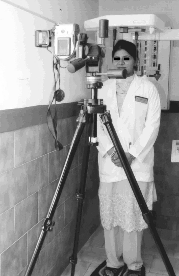
Positioning of the Subject for the photographic technique
The Camera was placed at a distance of 90 cms in front of the subject. The height of the camera was so adjusted such that the lower border of the mirror attached to the top of the camera coincided with the subjects’ eye level. This ensured that the level of each subject’s eyes was constant in relation to the lens and the camera flash. A plumb line was attached to the cephalostat machine beside the subject which acted as the vertical reference line.
The flash of the camera was set at the ‘always on’ mode that ensured that its reflection could be detected in the subjects’ pupils in every image because the subjects were asked to look straight towards the camera. As the subject’s eyes were focused at the same level, the outermost convexity of the eyeball reflected the flash.
Four frontal view images were taken for each subject in the following positions: mouth closed, smiling, biting on a disposable wooden spatula passing through the maxillary canines, biting on the fox plane.
Lines and Angles
Analysis was done using a software, Corel Draw version 9.0. Landmark points were located on the images and lines were drawn between them. The various lines drawn were:
Image 1 (Mouth Closed)
Interpupillary line (IP)—line joining the center of the reflection points of the camera’s flash on the pupils of the subject’s eyes.
Intercommissure line (I COM)—line joining the angles of the mouth with mouth closed.
Facial midline (FM)—line joining the mid-point of the inner canthii of the eyes and center of the philtrum of the upper lip (Figs. 3, 4, 5, 6).
Fig. 5.
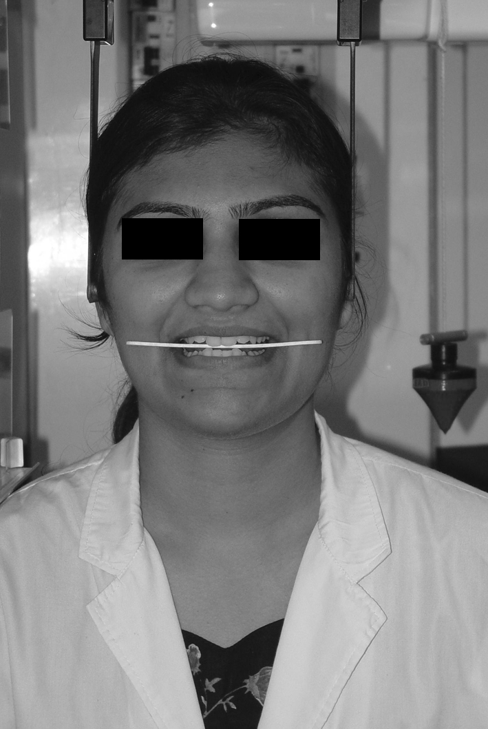
Biting on a wooden spatula
Fig. 3.
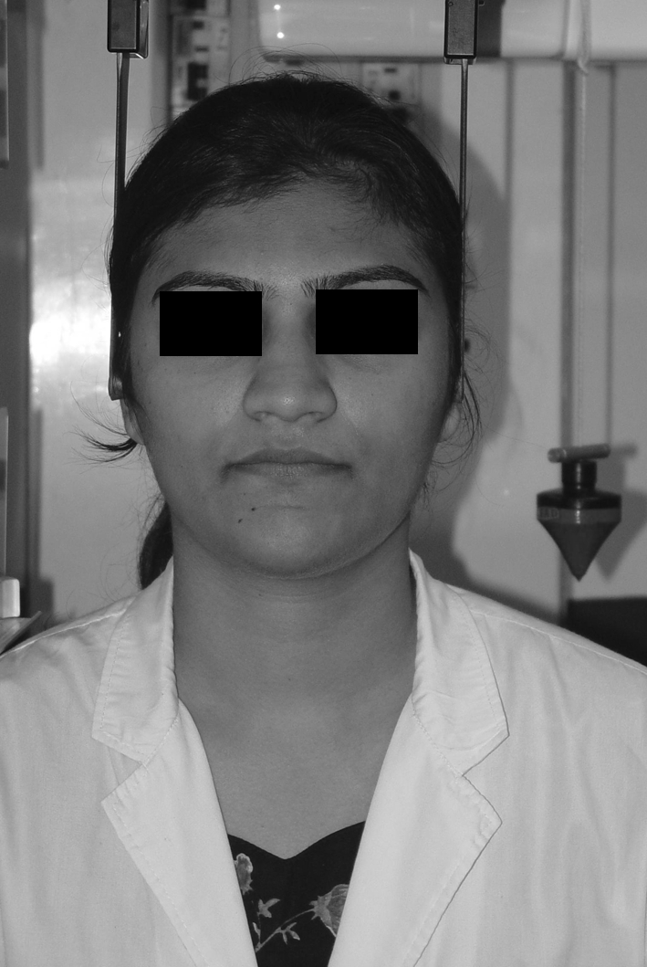
Mouth closed
Fig. 4.
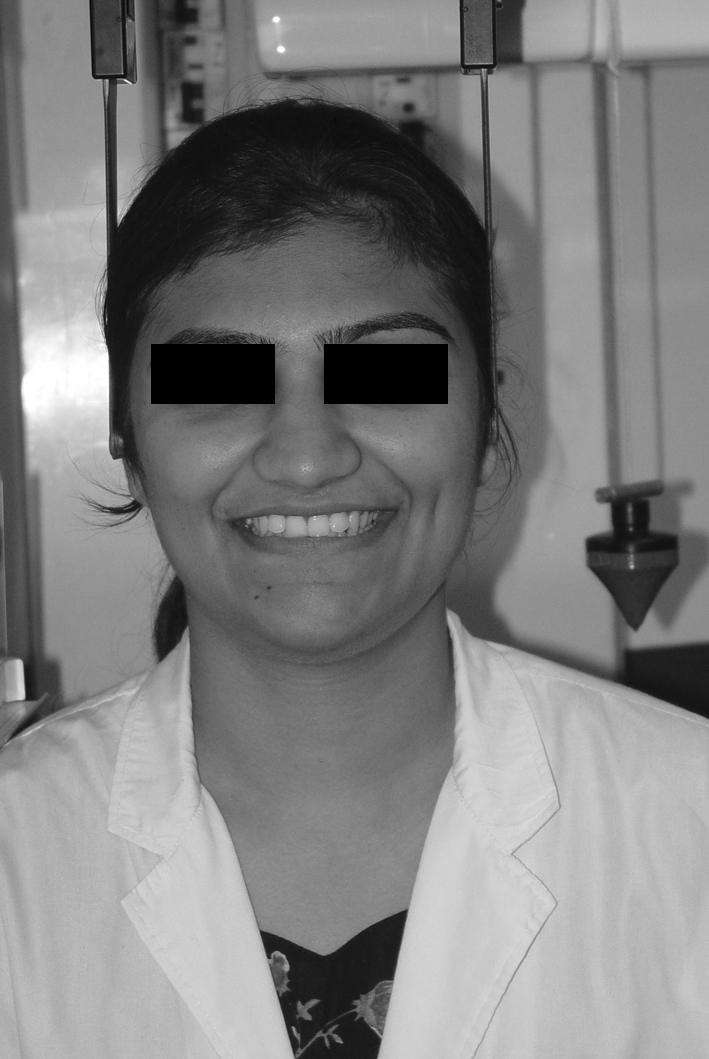
Smiling
Fig. 6.
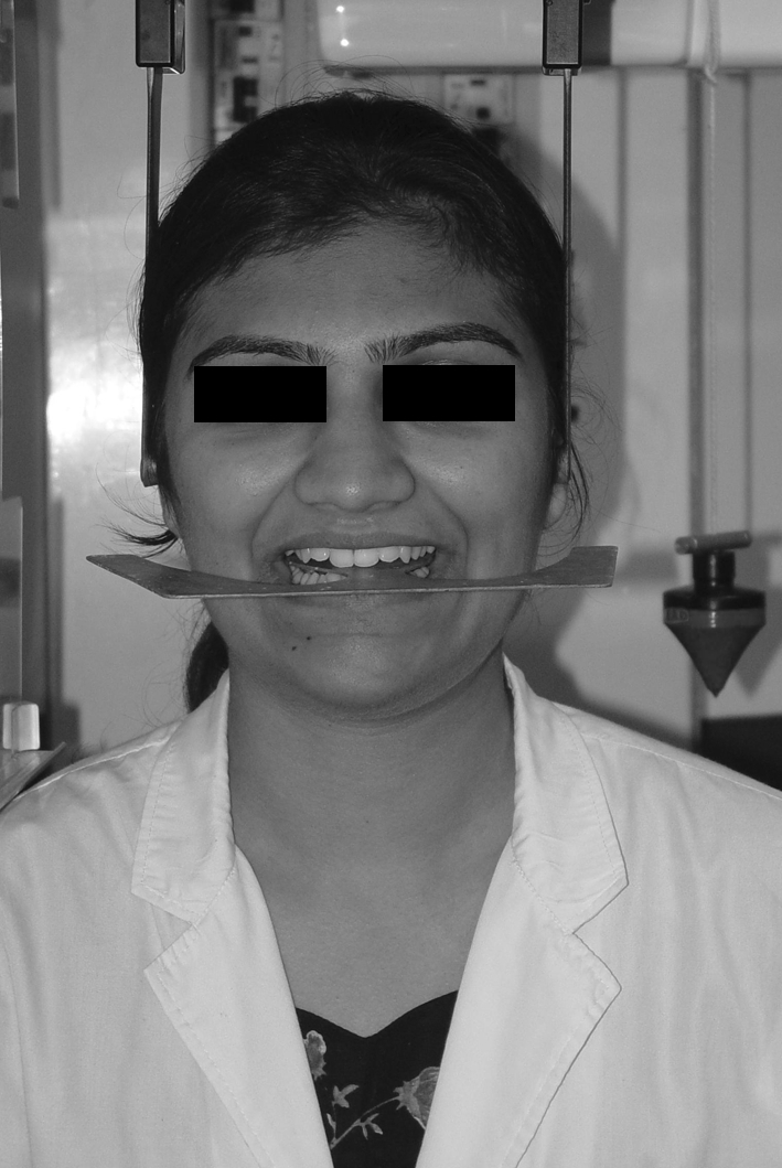
Biting on the Fox plane
Image 2 (Smiling)
Interpupillary Line (IP).
Intercommissure Line (ICS)—line joining the angles of the mouth while smiling.
Image 3 (Biting on a Wooden Spatula)
Interpupillary Line (IP).
Intercuspid Line (IC)—line joining the tips of the right and left maxillary canines in contact with the wooden spatula.
Image 4 (Biting on the Fox Plane)
Cant of Occlusal Plane (assessed by Fox Plane)—Landmarks located on the upper border of the outer edges of the Fox plane in the anterior region and a line drawn between them.
The upper and lower points of the plumb line were identified and a line drawn between them. This acted as a vertical reference line. A line at a right angle to this was taken as the true horizontal. The line joining the center of the ear posts inserted into the EOM on the right and left sides was found to be perpendicular to the plumb line and hence can be represented as the true horizontal. The same was used as a reference against which the angles of the above mentioned facial lines were calculated in each image.
After the angular measurements were made, linear measurements to find the difference between the right and left sides were done for two reference lines—IP and IC.
Linear IP: The difference between the level of the pupils on the right and left sides.
Linear IC: The difference between the level of the tip of the canines on the right and left sides.
As the angular measurements of IP and IC lines with the true horizontal were already known, linear measurements could be taken out using simple geometrical principles.
As shown in the diagram below, a perpendicular was dropped from one landmark point to the true horizontal (p). The length of the reference line between the two landmarks (h) was found out using the same software. 
Sin θ = p/h. Since, variables θ and h were already found out, it was possible to calculate p, which is the linear difference between right and left sides (Figs. 7, 8).
Fig. 7.
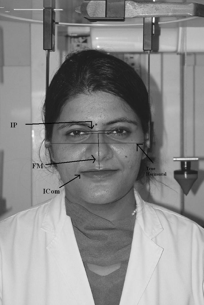
Shows that landmark points were located on the images and lines drawn between them
Fig. 8.
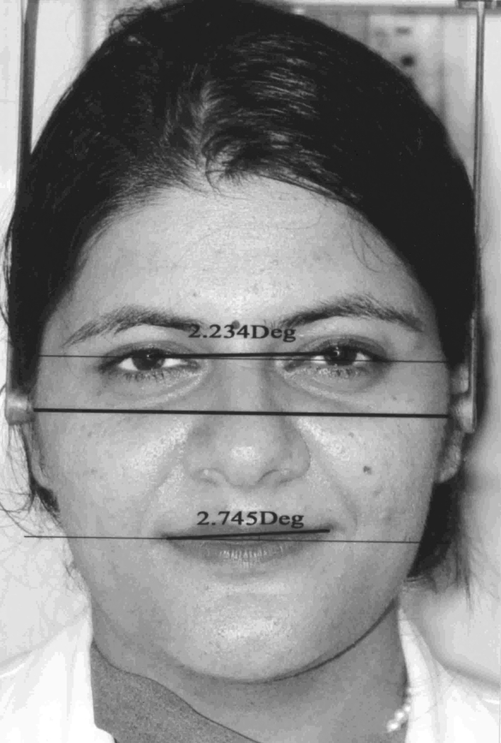
Shows the angles calculated between IP and I CS with the true horizontal (represented by a line perpendicular to the plumb line)
Reproducibility of Measurements
A test was performed to verify the accuracy of the image taken from the digital camera. The digital camera was set up perpendicular to a card on which a known angle had been drawn, the images were acquired. After downloading the images from the camera to the computer, measurements were done using COREL DRAW. The angles obtained from the computer matched those drawn on the card to within ±0.1°.
Results
All the measurements were made on the left side of the subject’s face.
Positive values are those diverging counter clockwise from the horizontal and Negative values are those diverging clockwise from the horizontal. For the facial midline, angles less than 90° diverge clockwise from the vertical and angles greater than 90° diverge counter clockwise from the vertical. Using principles of geometry, linear measurements were recorded from the angular measurements for some subjects.
The first objective of the study was to evaluate whether asymmetry exists between the right and left sides of the face in subjects with no obvious facial asymmetry. It is evident from Table 1 that all the mean values of IP, ICOM, FM, ICS, IC and Fox plane does not coincide with the true horizontal represented as “zero”. This means that there is obvious asymmetry that exists between the right and left sides of the face.
Table 1.
Descriptive statistics
| N | Minimum | Maximum | Mean | SD | |
|---|---|---|---|---|---|
| IP | 100 | –3.148 | 4.274 | 0.11411 | 1.45101 |
| ICOM | 100 | –3.865 | 4.935 | 0.33743 | 1.94943 |
| FM | 100 | 82.951 | 94.680 | 88.85 | 2.08361 |
| ICS | 100 | –3.749 | 4.591 | 0.0979 | 1.87263 |
| IC | 100 | –2.927 | 5.405 | 0.31115 | 2.02170 |
| Fox Plane | 82 | –3.892 | 6.203 | 0.65322 | 1.99833 |
| Linear IP | 22 | 0.299 | 2.716 | 1.299 | 0.74566 |
| Linear IC | 24 | 0.281 | 2.875 | 1.193 | 0.59245 |
Table 1 shows the minimum and maximum values (range), mean standard deviation of the data, where ‘N’ denotes the number of subjects.
The next objective was to estimate the range of facial asymmetry. Table 1 shows that all the measured angles are distributed over several degrees of asymmetry existing in different individuals.
Graphs 1–6 were drawn to depict the range of asymmetry values for the various variables, i.e., IP, ICOM, FM, ICS, IC and Fox plane.
To determine whether there was any relation between the various variables, correlations between the various variables were studied.
Karl Pearson’s correlation coefficient (r) was calculated for the various values and scatter diagrams were drawn depicting the correlation.
This correlation coefficient was subjected to ‘t’ test and the ‘p’ value was used to find out the level of statistical significance (p < 0.05—significant, p < 0.01-highly significant and p < 0.001-very highly significant). These were done using SPSS statistical package, version 10.
Table 2 shows the values of correlation coefficient ‘r’ and the corresponding ‘p’ values between the various variables for 100 subjects.
Table 2.
Correlations between various variables
| ICOM | FM | ICS | IC | Fox plane | Linear IC | Linear IP | |
|---|---|---|---|---|---|---|---|
| IP | |||||||
| r′ | 0.640 | 0.361 | 0.703 | 0.619 | 0.632 | 0.442 | –0.212 |
| p | 0.000 | 0.000 | 0.000 | 0.000 | 0.000 | 0.031 | 0.343 |
| N | 100 | 100 | 100 | 100 | 82 | 24 | 22 |
| ICOM | |||||||
| r′ | 0.493 | 0.708 | 0.637 | 0.591 | 0.583 | 0.140 | |
| p | 0.000 | 0.000 | 0.000 | 0.000 | 0.003 | 0.535 | |
| N | 100 | 100 | 100 | 82 | 24 | 22 | |
| FM | |||||||
| r′ | 0.357 | 0.368 | 0.290 | 0.556 | 0.227 | ||
| p | 0.000 | 0.000 | 0.008 | 0.005 | 0.309 | ||
| N | 100 | 100 | 82 | 24 | 22 | ||
| ICS | |||||||
| r′ | 0.597 | 0.561 | 0.497 | –0.145 | |||
| p | 0.000 | 0.000 | 0.014 | 0.520 | |||
| N | 100 | 82 | 24 | 22 | |||
| IC | |||||||
| r′ | 0.689 | 0.540 | –0.107 | ||||
| p | 0.000 | 0.006 | 0.635 | ||||
| N | 82 | 24 | 22 | ||||
| Fox plane | |||||||
| r′ | 0.514 | –0.077 | |||||
| p | 0.050 | 0.794 | |||||
| N | 15 | 14 | |||||
| Linear IC | |||||||
| r′ | 0.470 | ||||||
| p | 0.036 | ||||||
| N | 20 | ||||||
r′ = Karl Pearsons coefficient of correlation
It is evident from the table that the correlation between IP and ICOM ‘r’ is .640 while the corresponding ‘p’ values being 0.000, which is statistically very highly significant (p < 0.001) This relation is plotted in the scatter diagram 1, which shows the positive correlation between IP and ICOM—as the values of IP increases, the corresponding ICOM value also increases.
Likewise correlation between variables like IP and FM, IP and ICS, IP and IC, IP and Fox plane shown in various Scatter diagrams 2–5, respectively, are found to be statistically very highly significant.
The correlation between Linear IP and Linear IC also showed a positive correlation depicted in scatter diagram 6.
Results show that there is a high positive correlation between the various variables, which is statistically very highly significant. Since all the measurements were made on the left side of the subjects’ face, a positive mean value for all the variables implies that the left side of the face is at a higher level than the right side indicative of a definite facial asymmetry.
Discussion
Facial esthetics evaluation is an important part of the prosthodontic treatment planning and one of its primary goals is the attainment of best facial esthetic appearance for a given patient. This study is the photographic evaluation of asymmetry of the face in hundred subjects with no clinically discernible facial asymmetry. In this study, the entire photographic technique was standardized.
Lombardi pointed out that detailed esthetic judgement can only be made by viewing patients from the front in conversation, various facial expressions and smiling. Hence in our study, we took frontal photographs of the subjects in different positions for better visual perception and application to denture esthetics [4].
As the Interpupillary line was one of the reference lines in the study, it was sometimes difficult to locate the center of the pupil on the image of the subject by inspection because the upper eyelid was superimposed on part of the pupil area especially when the subject was smiling and both the eyelids tended to close. This study used the flash reflection from the pupil area, which was seen as a clear white area on the centre of pupil. This made it easier to locate the centre of pupil even when the eyelids overlapped part of the pupil. For this purpose we used a mirror on top of the camera as an external source of eye reference. The subjects tended to look up more when the mirror was used as a reference [3].
The occlusal plane position is the foundation of clinical treatment and one of the most important criteria used to judge the degree of treatment success. In our study, we used the Fox plane and the wooden spatula (IC) to represent the cant of occlusal plane.
The Fox plane and the IC do not coincide with the true horizontal suggestive of a definite canting of the occlusal plane, which varies from individual to individual.
Due to these individual variations, a standardized approach in locating the occlusal plane may result in less than ideal esthetics in the final restoration [5]. According to the studies done by Woo [2], Shah and joshi [6], Peck and Peck [7], the right side was found to be significantly larger than the left side. The difference was particularly marked in the vertical measurement of parietal bone, which would have the effect of placing the External Auditory Meatus (EOM) lower on right side. However, certain other studies, like that of Vig and Hewitt [8], have shown asymmetry, but the left side was found to be larger than the right side and the possible reason for this sidedness was to compensate for hemispheric laterality [2].
We found that the left side of the face is at a higher level than the right side. In the present study, we attempted to bring the EOM of the subject at the same level by inserting the ear posts of the cephalostat. The arrangement simulates the mounting of the casts on the articulator where the auditory pins are situated at the same level.
Implications in Prosthodontics
When casts are mounted on the articulator by means of a facebow transfer, the auditory pins of the articulator being situated at the same horizontal level corresponding to the EOM on both right and left sides of the patient’s face comes to fall at the same horizontal level.
But, as found out in the study, the EOM’s are not situated at the same horizontal level.
Hence, when working casts are mounted on an articulator by means of a facebow transfer, the correct angulation for esthetic placement of restoration (Long span Fixed Partial Denture) or replacement of teeth by complete or partial dentures can be expected to be slightly clockwise or counter clockwise to the axis of the articulator depending on individual variations.
If this angulation is ignored by the clinician and technician and the arrangement of teeth is done according to the articulator’s horizontal axis, the arrangement might appear acceptable on the articulator but may look unaesthetic in the patient’s mouth [2].
The results of our study show that the means of all facial lines corresponding to various facial features were having a counter clockwise angulation, which is statistically very highly significant.
This implies that the left side of the face is at a higher level than the right side. Thus, as shown in the study, facial asymmetry is a common human characteristic.
Clinical Implications
Our study can be put to use in day to day clinical practice by taking the digital photographs of such patients, downloading them on to the computer and subjecting them to analysis.
This can be done by locating the landmarks and measuring the angles between the various landmarks and the true horizontal, the same way as was done in the study. From the angular measurements, linear differences can be found out between the right and left sides and the arrangement of teeth can be done according to the individual variations between the right and left sides for the best possible esthetic result, thus, ensuring complete satisfaction of the patient.
Another way of communication with the dental laboratory is by the use of CLINOMETER [2, 9]
A CLINOMETER (Behrend clinometer, Teledyne Hanau, Buffalo, NY) is a visual aid in the form of a lined transparent plastic screen, which is attached to an earbow type of a face bow and placed on the patients face. The screen can be adjusted to several horizontal tilts from horizontal aspect in a clockwise and counter clockwise direction. The screen helps the clinician visualize horizontal and vertical facial characteristics that facilitate alignment of anterior restoration. This information can be sent to the laboratory, which can interpret the data with smaller version of adjustable screen. This facilitates the arrangement of teeth in conformity with the patient’s facial characteristics. Thus, the clinometer can be put to use in day to day clinical practice by taking the subtle facial asymmetries into consideration to provide the best esthetic result, ensuring complete satisfaction to the patient.
Electronic Supplementary Material
Footnotes
The study was conducted at Manipal College of Dental Sciences, Manipal in the Department of Prosthodontics, while I was doing my Post Graduation from Manipal.
References
- 1.Baum AT. A cephalometric evaluation of the normal skeletal and dental pattern of children with excellent occlusion. Angle Orthodont. 1951;21(2):96–103. doi: 10.1043/0003-3219(1951)021<0096:ACEOTN>2.0.CO;2. [DOI] [PubMed] [Google Scholar]
- 2.Namano S, Behrend D, Harcourt J, Wilson P. Angular asymmetries of the human face. Int J Prosthodont. 2000;13:41–46. [PubMed] [Google Scholar]
- 3.Cooke MS, Wei SHY. The reproducibility of natural head posture. A methodological study. Am J Orthod Dentofacial Orthopaedics. 1998;93:280–288. doi: 10.1016/0889-5406(88)90157-6. [DOI] [PubMed] [Google Scholar]
- 4.Zachrisson BU. Esthetic factors involved in anterior tooth display and the smile: vertical dimension. J Clin Orthod. 1998;32(07):432–445. [Google Scholar]
- 5.Rocco JDP. An individualized approach to locating the occlusal plane. Am J Orthod Dentofacial Orthopaedics. 1987;92:41–45. doi: 10.1016/0889-5406(87)90294-0. [DOI] [PubMed] [Google Scholar]
- 6.Shah S, Joshi M. An assessment of asymmetry in normal craniofacial complex. Angle Orthodont. 1978;48:141–148. doi: 10.1043/0003-3219(1978)048<0141:AAOAIT>2.0.CO;2. [DOI] [PubMed] [Google Scholar]
- 7.Peck S, Peck L, Kataja M. Skeletal asymmetry in esthetically pleasing faces. Angle Orthodont. 1991;61:43–48. doi: 10.1043/0003-3219(1991)061<0043:SAIEPF>2.0.CO;2. [DOI] [PubMed] [Google Scholar]
- 8.Vig PS, Hewitt AB. Asymmetry of the human facial skeleton. Angle Orthodont. 1975;45:125–129. doi: 10.1043/0003-3219(1975)045<0125:AOTHFS>2.0.CO;2. [DOI] [PubMed] [Google Scholar]
- 9.Shannon JL, Rogers WA. Communicating patients’ esthetic needs to the dental laboratory. J Prosthet Dent. 1991;65:526–552. doi: 10.1016/0022-3913(91)90293-6. [DOI] [PubMed] [Google Scholar]
- 10.Claman L, Patton D, Rashid R. Standardized portrait photography for dental patients. Am J Orthod Dentofacial Orthopaedics. 1990;98(3):197–205. doi: 10.1016/S0889-5406(05)81596-3. [DOI] [PubMed] [Google Scholar]
- 11.Farkas LG, Cheung G. Facial asymmetry in healthy North American caucasians. An anthropometrical study. Angle Orthod. 1981;51:70–77. doi: 10.1043/0003-3219(1981)051<0070:FAIHNA>2.0.CO;2. [DOI] [PubMed] [Google Scholar]
- 12.Peck H, Peck S. A concept of facial esthetics. Angle Orthodont. 1970;40:284–318. doi: 10.1043/0003-3219(1970)040<0284:ACOFE>2.0.CO;2. [DOI] [PubMed] [Google Scholar]
- 13.Richard KK, Djeng SK. Orientation of the plane of occlusion. J Prosthet Dent. 1990;64:31–36. doi: 10.1016/0022-3913(90)90149-7. [DOI] [PubMed] [Google Scholar]
- 14.Schudy FF. Cant of occlusal plane and axial inclinations of teeth. Angle Orthodont Apr. 1963;33:69–81. [Google Scholar]
- 15.Fischer B. Asymmetries of the dentofacial complex. Angle Orthodont. 1954;24:179–192. [Google Scholar]
- 16.Thompson JR. Asymmetry of the human face. J Am Dent Asso. 1943;30:1859–1871. [Google Scholar]
- 17.Wuerpel EH. On facial balance and harmony. Angle Orthodont. 1936;7:81–89. [Google Scholar]
Associated Data
This section collects any data citations, data availability statements, or supplementary materials included in this article.


