

Abstract
Today implant dentistry has made great inroads into the treatment modalities that are available in treating an edentulous patient. Popularity of a two implant retained overdenture has created a necessity to examine the various attachment systems being used and the stresses that are transmitted to the alveolar bone. Hence a Three dimensional Finite Element Analysis was done to analyze the stress distribution in the mandibular bone with implant-supported overdenture having Ball/O-ring and Magnet attachments of different diameters. A segment of the anterior region of the mandible was modeled with implant and the overdenture. Four different models were generated having Ball/O-Ring and Magnet Attachments. Forces of 10 N, 35 N and 70 N were applied from the horizontal, vertical and oblique directions respectively and the stress distribution studied. It was concluded that the greatest stress concentrations were seen at the crest of the cortical bone and could be reduced by using smaller sized attachments for implant supported-overdenture.
Keywords: Implant, Overdenture, Finite element analysis, Mandibular
Introduction
As life spans lengthen, a significant number of people outlive their teeth. Treating older patients, especially those with disabilities, may be a demanding challenge. The ultimate goal of treating such cases is to restore the patient to a level of satisfactory esthetics, physiological functions of speech, deglutition and mastication. The chief reason that complete mandibular dentures pose functional problems is because of poor retention. Also bone resorption is significantly greater in the mandible than in the maxilla of edentulous people. Since complete dentures rely on the residual alveolar ridge for support and retention, it is the mandibular dentures that suffer the most from this natural process [1]. Overdentures can be used as a treatment modality for the compromised completely edentulous patients especially in the mandibular arches. Retention for an overdenture is obtained by the implant supporting either retentive studs or magnet attachments similar to those used in natural tooth abutments [2]. The use of a minimal number of implants that is adequate for prosthodontic support and retention is also of economic benefit to the patient [3].
Various methods for evaluation of stress around dental implant system include Photoelastic Study, Finite Element Analysis and Strain Measurement on bone surface. The finite element method offers several advantages, including accurate representation of complex geometries, easy model modification and representation of the internal state of stress and other mechanical qualities [4].
In this study, a Three Dimensional Finite Element Model of a section of the mandible with an osseointegrated implant and overdenture is modeled having two types of attachment systems namely the Ball/O-ring and the Magnet system. The diameters of the attachments were varied and the stress distribution to the bone around the implant was studied. The loads were applied in the horizontal, vertical, and the oblique directions on the simulated overdenture.
Methodology
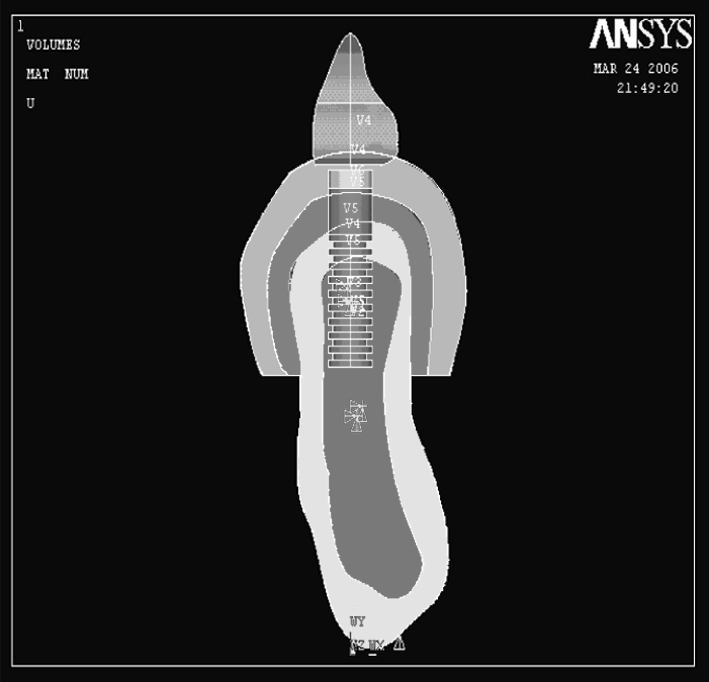
Four different finite element models, having an implant, mandibular bone section and overdenture were created for the study. The variables that were changed were the overdenture attachments as shown in (Table 1). A segment of bone around the implant with a length of 20 mm, height of 24 mm and width of 5 mm was modeled (Figs. 1, 2). The bone was modeled on D2 bone according to the classification given by Misch [5]. A Computer Tomography scan of the mandible was used to model the bone by plotting the key points on a graph and generating the same key points on the ANSYS Software 8 [6]. This was in accordance with the study conducted by Meijer et al. [4] where similar results were obtained on loading the entire mandible or a section of it at the interformainal region. Hence only a section was modeled for the study. The implant was modeled using appropriate dimensions as given by the manufacturer [mastero implant system Biohorizon]. The implant was modeled having length of 9 mm and width of 4 mm [7]. The surface of the simulated implant was threaded and the thread pitch was 0.4 mm. The inner diameter of the implant was 3.2 mm. The final number of threads that were present on the generated implant was 9 (Fig. 3).
Table 1.
Model designation and type of attachment
| Attachment type | Attachment diameter (mm) | |
|---|---|---|
| B1 | BALL/O-RING | 2.5 |
| B2 | BALL/O-RING | 4.0 |
| M1 | MAGNET | 4.0 |
| M2 | MAGNET | 4.5 |
Fig. 1.

Generation of key point for mandibular bone
Fig. 2.

Line plot for mandibular bone
Fig. 3.

Line plot for model B1 and M1
When the material properties—Young’s modulus (stress/strain) and Poisson’s ratio (lateral strain/longitudinal strain) were assigned, the simulated finite element model will behave like the actual prototype.
The ball attachment was modeled to be 2.5 mm [7] in diameter with a cuff height of 1 mm and an overall length of 4 mm [7] for the first model (Fig. 4) and 4 mm diameter with cuff height of 1 mm and an overall length of 4.75 mm for the second model as specified by the manufacturer [7] [Maestro implant system Biohorizon]. The silicone O-ring attachment is an O-shaped member with an inner radius and an outer radius. The first model had an inner radius of 1.25 mm and an outer radius of 4 mm. The second model had an inner radius of 2 mm and an outer radius of 4 mm.
Fig. 4.
Area Plot of model B1 with ball attachment
The magnet attachment was modeled to be of two diameters. The first magnet had a diameter of 4 mm [8] and length of 1.5 mm. The magnetic attraction of the magnet is 800 g. The second Magnet attachment had a diameter of 4.5 mm [8] and length of 1.7 mm. The magnetic attraction of the magnet was 910 g (Fig. 5), both the magnetic attachment was based on the Dyna magnetic system [8].
Fig. 5.
Area plot of model M1 with magnet diameter
The mucosa was modeled over the cortical bone with a uniform thickness of 2 mm. A section of the overdenture over the implant had been modeled. It consisted of an acrylic denture base and acrylic teeth. All materials used in this model were considered to be homogeneous isotropic and linearly elastic [10] (Table 2).
Table 2.
Material properties [9]
| Young’s modulus (Mpa) | Poission’s ratio | |
|---|---|---|
| Cortical bone | 13,400 | 0.30 |
| Trabecular bone | 1,370 | 0.31 |
| Ti6Al4V20 | 110,000 | 0.33 |
| NdFeB (magnet) | 160,000 | 0.24 |
| Oral mucosa | 0.00001 | 0.40 |
| Silicone | 240 | 0.29 |
Processing and Meshing
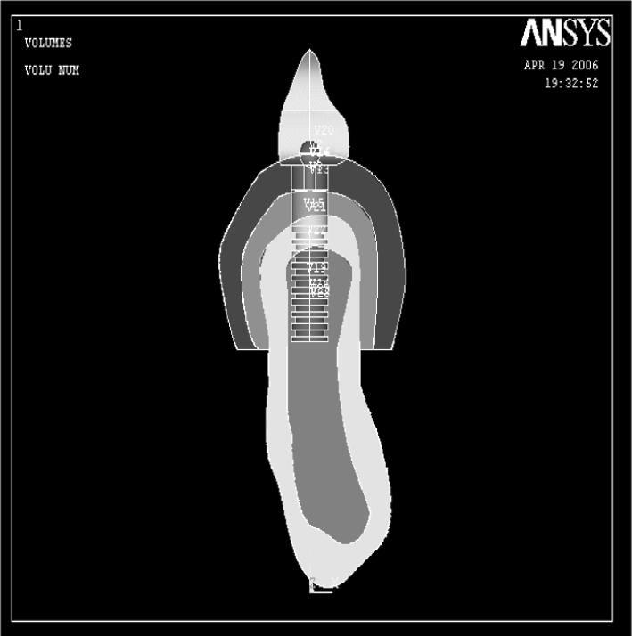
All preprocessed models should be processed to convert geometrical data into graphical representations. Once the graphical representations of the finite element model were obtained, meshing was done. The procedure of desiccating the finite element model into elements of equal size is called Meshing. The entire array of elements and nodes formed by meshing is called a Mesh. Tetrahedral (three-dimensional solid state structure with 10 nodes) elements were used because they were more harmonious with the design structure and hence will produce more accurate results. The material properties were incorporated into the model after meshing (Fig. 6).
Fig. 6.

Volume plot of model
Post Processing and Analysis
This is the final stage of the procedure wherein the prepared model was subjected to different parameters to simulate the field variables in different elements. Herein, the meshed model was subjected to horizontal, vertical (along long axis) and oblique (120° to long axis) forces to analyze the stress patterns formed in the bone. The four finite models were subsequently loaded from the horizontal (lingual), vertical, and oblique (buccal) directions with the force of 35, 70, 10 N respectively [11–13]. The forces were applied on the overdenture at the surface of the modeled tooth. The model is constrained in the mesial, distal and inferior directions and was allowed movement in the bucco-lingual plane. Stress levels according to Von-Mises criteria were calculated because Von-Mises stresses are most commonly reported in Finite Element Analysis studies to summarize the overall stress state at a point.
Results
Three dimensional models of the section of the mandibular bone segment comprising the cortical and trabecular bone, having an implant supported overdenture with various types of attachment (Ball and Magnet) were constructed. Forces of 10 N, 35 N and 70 N were applied in the horizontal, vertical and oblique directions respectively [11–13]. Stresses generated around the implant in the bone were studied.
The four different models studied are:
B1 = 2.5 mm Ball attachment
B2 = 4.0 mm Ball attachment
M1 = 4.0 mm Magnet attachment with 800 g magnetic attraction
M2 = 4.5 mm Magnet attachment with 910 g magnetic attraction
The material properties of the four different models were obtained from the literature [10]. The stress distribution was represented with different color-coding. Red being the highest followed by orange, yellow light green, green, light blue, blue and dark blue colors representing the stresses in the descending order. With these different colors the stress distribution pattern can be analyzed in the different models. The corresponding stress values for that particular color is also given at the bottom end of the photographs.
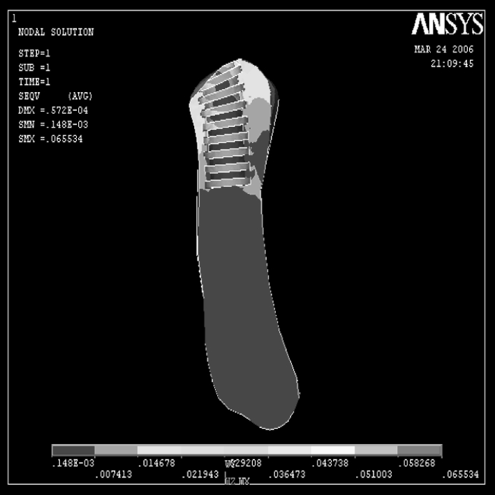
Stresses produced in the cortical bone were greatest with the model B2 when loaded with 70 N in the oblique direction. Overall it was seen that the stresses were concentrated near the neck of the implant in all of the sections of the cortical bone (Fig. 7). Stresses produced in the trabecular bone were greatest with the model B1when loaded with 70 N in the oblique direction (Fig. 8). The lowest stress concentration in the cortical bone was seen with horizontal force applied on model B1 (Fig. 9) and in the trabecular bone with model B1 in the horizontal direction (Fig. 10).
Fig. 7.
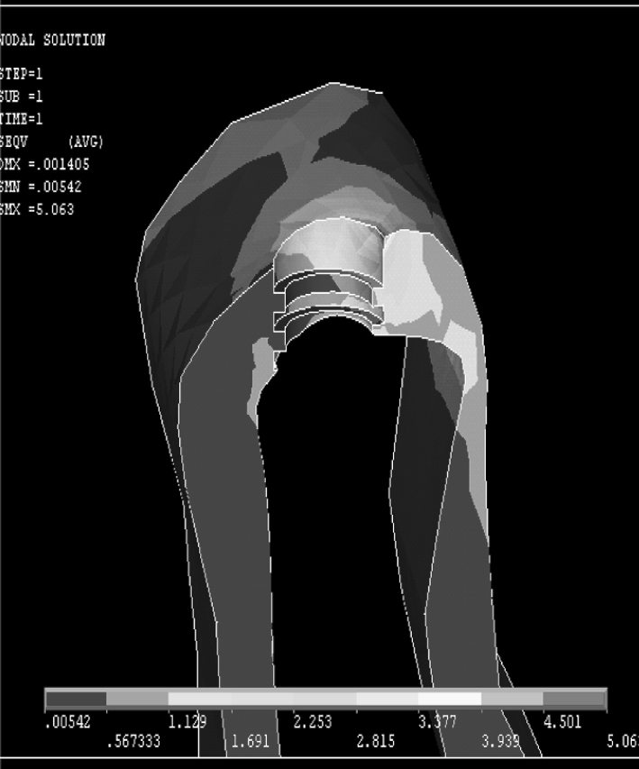
Greatest Stress generated in cortical bone in oblique loading in B2
Fig. 8.

Greatest Stress generated in trabecular bone in oblique loading in B1
Fig. 9.
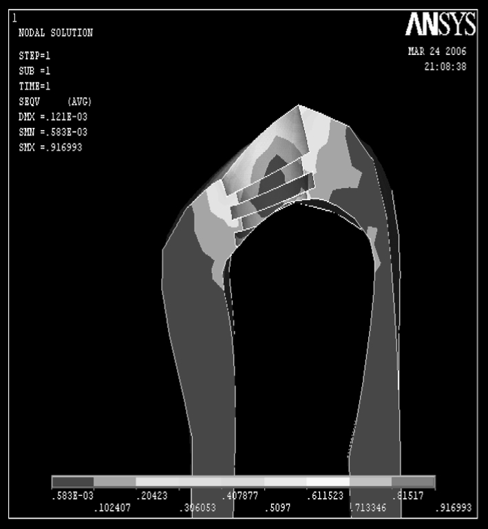
Cortical bone showing least stresses generated by B1 on horizontal loading
Fig. 10.
Trabecular bone showing least stresses generated by B1 on horizontal loading
Discussion
The McGill consensus statement on implant—supported overdentures was brought out in May of 2002 [1]. According to the consensus two implant- supported mandibular overdenture was considered to be the first choice of treatment for edentulous patients. Studies have shown that clear differences exist in the way stresses are transferred to the bone in a tooth-supported overdenture and an implant-supported overdenture The load transfer at the bone implant interface depends on (1) Implant geometry, (2) The type of loading, (3) Material properties of implant and prosthesis, (4) The nature of bone implant interface, (5) The quality and quantity of surrounding bone (6) Implant surface structure [2, 14].
Implant Geometry-Implant Dimensions
Cylindrical implants produce high shear stress on the bone; Increase in diameter increases the load bearing area by the square of its radius and the bending resistance by the fourth power of the radius. Studies show that stresses reach only a particular distance (approximately 10 mm in height) within the implant [5].
Type of Overdenture Attachment
There are various attachments that have been used with implant overdenture, the most common being the Bar-Clip attachment, Ball/O-ring attachment and the Magnet attachment. In vitro and in vivo [10, 15–17] studies show that the ball and O-ring attachment transferred less stress to the implants than the bar-clip attachment. In vitro studies [18] have shown that constant retentive properties and low retentive energy of magnet attachment could assist abutment preservation. Ball attachment are considered the simplest type of attachment for clinical application with tooth or implant supported overdentures [19]. Generally considered resilient, the specific design of the ball attachment may influence the amount of free movement thereby limiting its resiliency. Magnetic attachment has evolved over the years to become an additional option also available for use with the implant supported mandibular overdenture [20]. The development of closed field magnets of rare earth alloys substantiated magnets as an overdenture attachment system [21]. When wear induced retentive changes are considered, studies have shown that the ball attachment were found to have lost between 32% and 50% of their initial retentive force. By contrast magnets incurred a minimal reduction in retentive force of only 1.7–5.3% this is despite the microscopical corrosion that is seen within the stainless steel magnetic case [22]. The findings from comparative studies on the retentive force of ball and magnetic attachment identified the latter as the weaker attachment system. Inspite of this the magnetic attachment reflected the tendency to relatively maintain a reproducible and consistent force under wear simulation [23, 24]. This can be contributed largely to the inherent mode of retention being magnetic rather than frictional or mechanical. Stud attachment provide varying degree of resiliency in the vertical and horizontal directions. Magnetic attachment produces no vertical resiliency while quite effectively decreasing horizontal stress transmission to the abutment [25]. In the present study a comparison was made between the Ball/O-ring and the Magnet attachment. Different diameters for the attachments were used. Both the Ball/O-ring and the Magnet attachment have shown favorable stress distribution to the surrounding bone. It was observed that when the diameter of the attachments was increased there was an increase in the stress in the cortical bone. This result was consistent for both the ball and magnet attachment. This could be the result of the larger surface area of the bigger attachment, which transfers greater stresses on to the bone. Hence, if a larger diameter attachment is to be used then increasing the width of the implant will help to reduce the stresses to the cortical bone.
Type of Loading
The magnitude of the bite force is dependent on the force direction. In the present study three forces from different directions were selected: a horizontal bite force, a vertical bite force and an oblique bite force. The proportion of the force magnitude was 1:3.5:7 respectively. The vertical bite force was determined to be 35 N from studies which measured the bite force of edentulous patients with overdentures supported by implants in the mandible [13, 26]. This value was substituted in the above equation to derive the forces in the other directions. The loading force for the horizontal direction is 10 N, for the vertical direction it is 35 N and for the oblique direction it is 70 N. The horizontal force is applied in the lingual direction to simulate the constant force applied by the tongue. The oblique force is applied on the buccal surface to simulate the chewing forces. As the loading condition was different in each direction, comparisons between the models at the same loading conditions were made (Tables 3, 4; Graphs 1, 2). From the results of this study it is seen that irrespective of the loading conditions the stresses were concentrated at the crest of the cortical bone. This tendency of stress concentration around the implant neck, which was evident in all the models, is consistent with other results from Finite Element Analysis of loaded implants, as well as with findings from in vitro and in vivo experiments and clinical studies, which demonstrated bone loss around the implant neck [27].
Table 3.
Stresses developed in cortical and trabecular bone in models B1 and B2
| Direction of force | Stress in cortical bone (Mpa) | Stress in trabecular bone (Mpa) |
|---|---|---|
| 10 N (horizontal) | ||
| B1 | 0.916993 | 0.065534 |
| B2 | 1.419 | 0.105925 |
| 35 N (vertical) | ||
| B1 | 2.333 | 0.564464 |
| B2 | 2.428 | 0.417386 |
| 70 N (oblique) | ||
| B1 | 5.063 | 0.988089 |
| B2 | 6.256 | 0.627586 |
Table 4.
Stresses developed in cortical and trabecular bone in models M1 and M2
| Direction of force | Stress in cortical bone (Mpa) | Stress in trabecular bone (Mpa) |
|---|---|---|
| 10 N (horizontal) | ||
| M1 | 1.559 | 0.115590 |
| M2 | 1.810 | 0.118014 |
| 35 N (vertical) | ||
| M1 | 2.153 | 0.405691 |
| M2 | 2.224 | 0.352183 |
| 70 N (oblique) | ||
| M1 | 4.355 | 0.328770 |
| M2 | 4.674 | 0.307490 |
Graph 1.

Showing stresses in cortical bone in Mpa
Graph 2.

Graph showing stresses in trabecular bone in Mpa
Material Properties of Implant and Prosthesis
Implant biomaterials should have adequate strength and modulus of elasticity to withstand forces acting on them. Biomaterials like silicone, hydroxyapatite and carbon are intolerant to such forces; hence are not preferred as primary implant materials. Conversely, ceramics are avoided despite their strength due to their low modulus of elasticity. In conclusion, titanium alloys (Ti6Al4V), which offer superior strength and comparable modulus of elasticity, are preferable to transfer forces acting on them. An increase in force magnitude is deleterious to Osseointegration. Hence, the above factors should be considered to plan treatment so as to minimize force magnitude.
Nature of Bone Implant Interface
A critical aspect affecting the success or failure of an implant is the manner in which mechanical stresses are transferred from the implant to the bone. It is essential that neither implant nor bone be stressed beyond the long-term fatigue capacity. Any relative motion that can produce abrasion on the bone or progressive loosening of the implant should be avoided [28]. These requirements are met by osseointegrated implants by virtue of close apposition of the bone to implant in the angstrom level. The close apposition of titanium and bone at the angstrom level means that under any subsequent loading the interface moves as a unit without relative motion of the bone and titanium and with the possibility of transferring stress to all parts of the interface.
The Quality and Quantity of Bone Surrounding the Implant
The most common bone density that is present in the anterior mandible is the D2 type [5]. A finite element analysis conducted by Misch had predicted 100% success rate for implants placed in this type of bone. The type of bone present around the bone–implant interface spells the type of distribution of stress seen at the interface. Cortical bone can take better stresses as compared to trabecular bone. The ultimate compressive strength of cortical bone is 140–170 Mpa, where as the compressive strength of trabecular bone is 22–28 Mpa. In all the loading conditions the stress levels did not reach the maximum yield strength of mandibular bone, hence there would be no fracture of the bone. With the probability of excessive stresses being minimized, the focus of attention should be directed to the minimal amount of stress that is required to maintain a healthy bone–implant interface without causing bone disuse atrophy. The minimal stresses that is required for the deposition of the bone around the implant is about 1.3–1.7 Mpa [29]. It is observed from the studied loadings that the stress generated by the models were above this range. Hence both the Magnet as well as the Ball and O-ring attachments gives favorable stress distribution to the bone. This fact being laid down by the present study, the choice of the attachment now depends on the retention and stability that the attachment offers to the patient. Studies [30, 31] conducted on the satisfaction of the patient with implant-supported overdenture has revealed that they prefer the Ball O-ring attachment as compared to the Magnet attachment as far as retention and stability is concerned. Hence the best attachment to be used for implant-supported overdenture is the small diameter ball O-ring attachment.
The advantage of using Finite Element Analysis is that accurate representation of complex geometries can be made, the models can be easily modified and internal state of stress and other mechanical quantities can be represented [32, 33]. There were certain limitations pertaining to the present study. Finite Element Analysis is a mathematical in vitro study that may not simulate the clinical situation completely. A state of optimal osseointegration was assumed between the cortical bone, trabecular bone and the implant. This may not occur in clinical situations. All materials were assumed to be linearly elastic and homogeneous in nature whereas, bone is viscoelastic, anisotropic and heterogeneous material. The resultant stress values obtained may not be accurate quantitatively but are generally accepted qualitatively [32]. Chewing forces are dynamic in nature, but the loads applied in this study were static loads. In the present study only a segment of the mandible and overdenture was considered. Prosthesis movement, retention and stability were not considered. Due to the limitation pertaining to the study, further research regarding Three-dimensional Finite Element Analysis combined with long term clinical evaluation is required.
Conclusion
Within the limitations of the study it was seen that as the diameter of the attachment increases there was a resultant increase in the magnitude of stress that is transferred to the cortical bone. The greatest stress concentrations were seen at the crest of the cortical bone in all the models irrespective of the loading conditions. It was also deduced that the small diameter attachment is the better attachments to be used for implant supported-overdenture in terms of minimizing the stresses to the bone.
Contributor Information
Jins John, Email: drjinsjohn@hotmail.com.
V. Rangarajan, Email: drvranga@gmail.com
References
- 1.Feine JS, Carlsson GE, Awad MA, Chehade A, Duncan WJ, Gizani S, et al. The McGill consensus statement on overdentures. Mandibular two-implant overdentures as first choice standard of care for edentulous patients. Gerodontology. 2002;19(1):3–4. doi: 10.1111/j.1741-2358.2002.00003.x. [DOI] [PubMed] [Google Scholar]
- 2.Mericske-Stern R. Treatment outcome with implant supported overdentures: clinical consideration. J Prosthet Dent. 1998;79:66–73. doi: 10.1016/S0022-3913(98)70196-9. [DOI] [PubMed] [Google Scholar]
- 3.Celik G, Uludag B. Photoelastic stress analysis of various retention mechanisms on 3-implant-retained mandibular overdentures. J Prosthet Dent. 2007;97(4):229–235. doi: 10.1016/j.prosdent.2007.02.006. [DOI] [PubMed] [Google Scholar]
- 4.Meijer HJA, Starmans FJ, Steen WH, Bosman FA. Loading conditions of endosseous implants in an edentulous human mandible. A three-dimensional finite element study. J Oral Rehabil. 1996;23:757–763. doi: 10.1046/j.1365-2842.1996.d01-185.x. [DOI] [PubMed] [Google Scholar]
- 5.Misch CE (2005) Dental implant prosthetics. Mosby, Inc
- 6.Cruz M, Wassall T, Toledo EM, Barra L, Lemonge A. Three-dimensional finite element stress analysis of a cuneiform-geometry implant. Int J Oral Maxillofac Implants. 2003;18(5):675–684. [PubMed] [Google Scholar]
- 7.Mastero product catalog: BioHorizon (2004)
- 8.Biesaga R (2004) Dyna magnet manual. Dyna Magnet Inc
- 9.Fujimoto T, Niimi A, Murakami I, Ueda M. Use of new magnetic attachments for implant-supported overdentures. J Oral Implantol. 1998;24(3):147–151. doi: 10.1563/1548-1336(1998)024<0147:UONMAF>2.3.CO;2. [DOI] [PubMed] [Google Scholar]
- 10.Geng JP, Tan KBC, Liu GR. Application of finite element analysis in implant dentistry: a review of literature. J Prosthet Dent. 2001;85:585–598. doi: 10.1067/mpr.2001.115251. [DOI] [PubMed] [Google Scholar]
- 11.Mericske-Stern R, Overdentures ZG. An alternative implant methodology for edentulous patients. Int J Prosthodont. 1993;6:203–208. [PubMed] [Google Scholar]
- 12.Koolstra JH, Van eijden TMGJ, Naeije M, Weijs WA (1988) A three-dimensional model of the human masticatory system predicting maximum possible bite forces. J Biomech 21:563–576 [DOI] [PubMed]
- 13.Kampen FMC, Bilt A, Cune MS, Bosman F. The influence of various attachment types in mandibular implant retained overdentures on maximum bite force and EMG. J Dent Res. 2002;81(3):170–173. doi: 10.1177/154405910208100305. [DOI] [PubMed] [Google Scholar]
- 14.Eskitascioglu G, Usumez A, Sevimay M, Soytian E. The influence of occlusal loading location on stresses transferred to implant supported prosthesis and supporting bone: a three-dimensional finite element analysis. J Prosthet Dent. 2004;91:144–150. doi: 10.1016/j.prosdent.2003.10.018. [DOI] [PubMed] [Google Scholar]
- 15.Kenny R, Richards MW. Photoelastic stress patterns produced by implant retained overdentures. J Prosthet Dent. 1998;80:559–564. doi: 10.1016/S0022-3913(98)70032-0. [DOI] [PubMed] [Google Scholar]
- 16.Tokuhisa M, Matsushita Y, Koyano K. In vitro study of mandibular overdenture retained with ball, magnet or bar attachment: comparison of load transfer and denture stability. Int J Prosthdont. 2003;16:128–134. [PubMed] [Google Scholar]
- 17.Rutkunas V, Mizutani H (2004) Retentive and stabilizing properties of stud and magnetic attachments retaining mandibular overdenture. an in vitro study. Stomatol Baltic Dent Maxillofac J 6:85–90
- 18.Preiskel H (1996) Overdentures made easy: A guide to implant and tooth supported prosthesis. Quentessence, London
- 19.Wiemeyer Agar JR, Kazemi RB. Orientation of retentive matrices on spherical attachments independent of implant parallelisim. J Prostho Dent. 2001;86(4):434–437. doi: 10.1067/mpr.2001.118365. [DOI] [PubMed] [Google Scholar]
- 20.Riley MA, Walmsley AD, Harris IR. Magnets in prosthetic dentistry. J Prosthet Dent. 2001;86(2):137–142. doi: 10.1067/mpr.2001.115533. [DOI] [PubMed] [Google Scholar]
- 21.Doukas D, Michelinakis G, Smith PW, Barclay CW. The influence of interimplant distance and attachment type on the retention characteristics of mandibular overdentures on 2 implants: 6-month fatigue retention values. Int J Prosthodont. 2008;21(2):152–154. [PubMed] [Google Scholar]
- 22.Gulizio MP, Agar JR, Kelly JR. Taylor TD effect of implant angulation upon retention of overdenture attachments. J Prosthodont. 2005;14(1):3–11. doi: 10.1111/j.1532-849X.2005.00005.x. [DOI] [PubMed] [Google Scholar]
- 23.Michelinakis G, Barclay CW, Smith PW. The influence of interimplant distance and attachment type on the retention characteristics of mandibular overdentures on 2 implants: initial retention values. Int J Prosthodont. 2006;19(5):507–512. [PubMed] [Google Scholar]
- 24.Leung T, Preiskel HW. Retention profiles of stud-type precision attachments. Int J Prosthodont. 1991;4(2):175–179. [PubMed] [Google Scholar]
- 25.Haraldson T, Jemt T, Stalbald P, Lekholm U. Functions in subjects with overdentures supported by osseointegrated implants. Scand J Dent Res. 1988;96:235–242. doi: 10.1111/j.1600-0722.1988.tb01550.x. [DOI] [PubMed] [Google Scholar]
- 26.Brocher L, Reichart P. Three dimensional stress distribution around a dental implant at different stages of interface development. J Dent Res. 1983;62(2):155–159. doi: 10.1177/00220345830620021401. [DOI] [PubMed] [Google Scholar]
- 27.Chen C, Brudvik JS, Lloyd A, Jeffrey M, Rubenstein E, Chitswe K, Ariel J. Raigrodski freedom of rotation of selected overdenture attachments: An in vitro study. J Prosthet Dent. 2011;106(2):78–86. doi: 10.1016/S0022-3913(11)60099-1. [DOI] [PubMed] [Google Scholar]
- 28.Meijer HJA, Kuiper JH, Starmans FJM, Bosman FJM. Stress distribution around dental implants: influence of superstructure, length of implant and height of mandible. J Prosthet Dent. 1992;68:96–102. doi: 10.1016/0022-3913(92)90293-J. [DOI] [PubMed] [Google Scholar]
- 29.Maeda Y, Horisaka M, Yagi K. Biomechanical rationale for a single implant-retained mandibular overdenture: an in vitro study. Clin Oral Impl Res. 2008;19(3):271–275. doi: 10.1111/j.1600-0501.2007.01425.x. [DOI] [PubMed] [Google Scholar]
- 30.Burns DR, John UW, Ronald EK, Jr, Beck DA. Prospective clinical evaluation of mandibular implant overdenture: Part I-retention stability and tissue response. J Prosthet Dent. 1995;73:354–363. doi: 10.1016/S0022-3913(05)80331-2. [DOI] [PubMed] [Google Scholar]
- 31.Chan MFWY, Johnson C, Howell RA, Cowood JI. Prosthetic management of the atrophic mandible using endosseous implants and overdentures. Br Dent J. 1995;179:329–337. doi: 10.1038/sj.bdj.4808917. [DOI] [PubMed] [Google Scholar]
- 32.Żmudzki J, Chladek W, Krukowska J. Attachments of implant retained tissue supported denture under biting forces. Arch Comput Mater Sci Surf Eng. 2009;1(1):13–20. [Google Scholar]
- 33.Bathe K-J (2002) Finite element procedure, 6th edn. Prentice-Hall of India Pvt Ltd