Abstract
In this study, compliant latex thin-walled aneurysm models are fabricated to investigate the effects of expansion of shape memory polymer foam. A simplified cylindrical model is selected for the in-vitro aneurysm, which is a simplification of a real, saccular aneurysm. The studies are performed by crimping shape memory polymer foams, originally 6 and 8 mm in diameter, and monitoring the resulting deformation when deployed into 4-mm-diameter thin-walled latex tubes. The deformations of the latex tubes are used as inputs to physical, analytical, and computational models to estimate the circumferential stresses. Using the results of the stress analysis in the latex aneurysm model, a computational model of the human aneurysm is developed by changing the geometry and material properties. The model is then used to predict the stresses that would develop in a human aneurysm. The experimental, simulation, and analytical results suggest that shape memory polymer foams have potential of being a safe treatment for intracranial saccular aneurysms. In particular, this work suggests oversized shape memory foams may be used to better fill the entire aneurysm cavity while generating stresses below the aneurysm wall breaking stresses.
Keywords: Aneurysm, Shape memory polymer foam, Embolic device, Aneurysm rupture, Latex vascular model
1 Introduction
Intracranial saccular aneurysms pose a significant threat of morbidity and mortality from subarachnoid hemorrhage by rupture (Schievink 1997; Wijdicks et al. 2005); thus, many research efforts aim to better understand the aneurysm’s behavior and material properties (David and Humphrey 2003; Shah and Humphrey 1999; Kyriacou and Humphrey 1996; Akkas 1990; Austin et al. 1989; Hung and Botwin 1975; Simkins and Stehbens 1973; Ferguson 1972; Scott et al. 1972; Suzuki and Ohara 1978; Steiger et al. 1989; Abruzzo et al. 1998). These aneurysms are sac-like focal dilatations of the arterial wall that are commonly found in or near the circle of Willis, which are the major network of arteries that supplies blood to brain.
To prevent potential risk of subarachnoid hemorrhage from a rupture of one of these aneurysms, treatment methods that surgeons employ is to clip the neck of the aneurysm micro-surgically or embolize it with Guglielmi detachable coils (GDCs). After FDA approval of GDCs in 1995, endovascular coiling treatments have become more common and have significantly improved the treatment for intracranial aneurysms. A variety of modified coils have been proposed since the FDA approval (Ahuja et al. 1993; Kallmes et al. 1998a; Murayama et al. 1999, 2002; Tamatani et al. 1997). Recently, novel devices and treatments have been proposed, such as balloon-assisted coils, flow-diversion devices (Kallmes et al. 2007; Lylyk et al. 2009; Szikora et al. 2010; Fiorella et al. 2008, 2009; Leonardi et al. 2008; Appelboom et al. 2010), open- and closed-cell stent designs (Ionita et al. 2009, 2008; Biondi et al. 2007; Liang et al. 2010; Lubicz et al. 2009; Fiorella et al. 2006), bioactive and coated coils (Gunnarsson et al. 2009; Gaba et al. 2006; Geyik et al. 2010; Bendszus et al. 2007; Veznedaroglu et al. 2008; Wakhloo et al. 2007; Hirsch et al. 2007), and embolic materials (Cekirge et al. 2006; Molyneux et al. 2004; Piske et al. 2009).
Although coiling methods have improved the available treatment options on intracranial aneurysms, some limitations still exist. For instance, dependent on the coil delivery technique, there is approximately 1–5% chance of intraprocedural rupture (i.e., the rupture of aneurysms during endovascular coil embolization) (Brisman et al. 2006; Murayama et al. 2003; Tummala et al. 2001; Cloft and Kallmes 2002; Brisman et al. 2005; Henkes et al. 2004; Brilstra et al. 1999). In addition, the occlusion of less than 50% of the aneurysm volume (Horowitz et al. 1997; Kallmes et al. 1998b), coil compaction, shifting, and possible migration of the coil out of the aneurysm can cause risks of aneurysm re-growth, rupture, or stroke (Choudhari et al. 2007; Willinsky 1999).
Shape memory polymer (SMP) foams are being investigated as an alternative to coils (Maitland et al. 2007). The functionality of these foams is a result of their shape memory behavior, which is broadly summarized in Fig. 1. The shape memory characteristic of the foams allows them to be crimped to a small size, delivered endovascularly, and then thermally expanded to achieve complete occlusion of the aneurysm. The SMP foam used in this study is a poly-urethane. Polyurethanes are generally considered to have good biocompatibility and are widely used in the implantable medical devices. The biocompatibility of the neat form of our materials has also been previously reported (Cabanlit et al. 2007). Volumetric expansion ratios of SMP foams up to 60X have been reported (Small et al. 2007). Tailored foams can completely fill the geometry of the aneurysm, and blood percolating through the porous structure produces a blood clot and foreign body reaction, which then leads to fibrosis and thus isolation of the aneurysm from the vascular lumen due to endothelialization at the base of the aneurysm neck similar to a successful GDC deployment case.
Fig. 1.
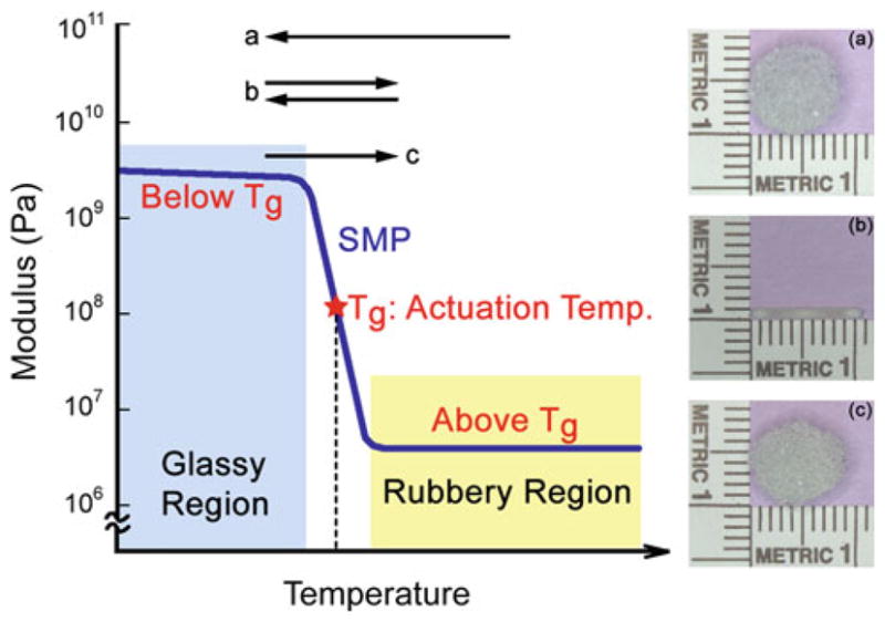
Description of the thermally actuated shape memory behavior in SMP foam. The foam is first fabricated into (a) its primary shape (e.g., 8-mm-diameter sphere) and then crimped, above the actuation temperature (i.e., the glass transition temperature Tg), into (b) its temporary shape (e.g., 1-mm-diameter cylinder). The foam is cooled to below the Tg to lock in the crimped configuration. Upon again heating through the Tg, the foam returns to (c) the original, primary shape
A critical factor in the feasibility of these foams as a treatment option is the pressure exerted by the expanding SMP foam on the aneurysm wall during deployment. Considering the aneurysm wall strength has been reported to be in the range of 700–5,000 kPa (Humphrey and Na 2002; MacDonald et al. 2000), it is not expected that rupture will occur due to foam expansion (Ortega et al. 2007). As a result, SMP foams have potential to improve the treatment for aneurysms.
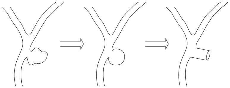
This work establishes a method for estimating the stresses exerted on the aneurismal wall by the expanding foam and thus assessing the possibility of aneurysm rupture during treatment. To estimate these stresses, a series of experiments are performed on an idealized cylindrical aneurysm model, and finite element simulations are performed to predict the stresses that would be experienced in an aneurysm wall during treatment. Figure 2 presents the simplification of an intracranial aneurysm to an idealized cylindrical model. Simplification of the aneurysm allows for applying cylindrical, thin-walled pressure vessel theory to estimate the stresses.
Fig. 2.
Schematic diagram of a saccular aneurysm near the bifurcation of an artery in the circle of Wills. Pictured is the idealization of the aneurysm into spherical and cylindrical shapes. The cylindrical model is used in the experiments and simulations performed in this work. Our cylindrical model ignores the boundary effect of distal end of the saccular aneurysm
Due to the low modulus of the SMP foam, the cylindrical aneurysm model is fabricated using latex, which is a compliant material that can conform to the expanding foam. Oversized SMP foams are then deployed to completely fill the latex model. A pattern of makers are placed on the outer surface of the latex aneurysm model. These markers are then monitored and used to estimate the circumferential stress.
The stresses exerted by SMP foam expansion in the latex aneurysm model are not expected to be the same as in the human aneurysm model due to the difference in material properties. Before we estimate the stresses of the cylindrical human aneurysm models, mechanical and analytical solutions are used to validate the latex aneurysm finite element simulations performed using ABAQUS®. The latex material properties are obtained by performing tensile tests on dogbone specimens, and the displacement of the latex during mechanical expansion is used as input. The resulting pressure the foam exerts on the latex, calculated by ABA-QUS, combined with the modulus of the aneurysm tissue is subsequently used to predict the stress that would result from deploying the foam in a cylindrical human intracranial aneurysm.
2 Materials
2.1 Shape memory polymer foam
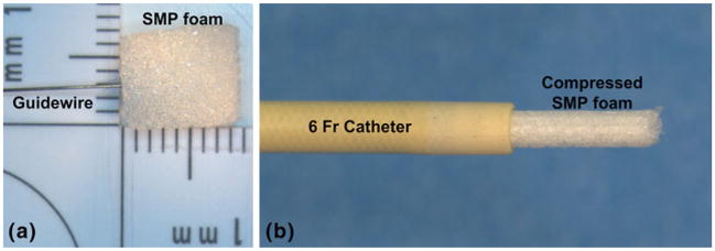
The shape memory polymer (SMP) foam used in this study was composed of hexamethylene diisocyanate (HDI), N,N,N′,N′-tetrakis (2-hydroxypropyl) ethylenediamine (HPED), and triethanolamine (TEA) (Wilson et al. 2007). The SMP foam, which had a glass transition temperature (Tg) of approximately 60°C, was cut using a biopsy punch (Sklar Trupunch™, Sklar Instruments, West Chester, Pennsylvania) into 10-mm-long cylinders that had diameters of 8 and 6 mm. Because the SMP foam has been observed to exhibit a loss of 7% in the expanded diameter during the first thermal actuation cycle (Maitland et al. 2009), it was preconditioned by performing one cycle of crimping and thermal expansion. The SMP foam was then threaded coaxially over a 0.38-mm-diameter nitinol guidewire (GUIDE-BB-10, Memry Corporation, Menlo Park, California) and crimped (SC150-42, Machine Solutions, Inc., Flagstaff, Arizona) for 10 min at 95°C (±1°C). This crimping process reduced the foam diameter to 1.38 ± 0.01 mm for 3 samples that had an initial diameter of 8 mm and a final diameter of 1.15 ± 0.01 mm for 3 samples that had an initial diameter of 6 mm. After crimping the foam, the temperature of the stent crimper was reduced by blowing dry house air into the machine for 2 h. This constrained cooling process allowed the SMP foam to cool to room temperature (23 ± 1°C) and thus ‘freeze’ the foam in its crimped state. The crimped foam was then placed in a 6 Fr catheter, as shown in Fig. 3, in preparation for deployment in the latex model.
Fig. 3.
Photograph of the SMP foam and the corresponding delivery device. Pictured are an a 8 mm diameter of cylindrical SMP foam sample with a guidewire and a b compressed SMP foam that has been passed through a 6 Fr catheter (ID = 1.78 mm, OD = 2.00 mm)
2.2 Latex
High ammonia natural rubber latex (Vytex®, Vystar Corporation, Duluth, Georgia) was used to make the aneurysm models. The liquid latex was filtered through a cone-shaped plastic mesh into a 2-oz-round glass bottle to remove all coagulation. The latex was then vortex-mixed (VM-3000, VWR International LLC, Radnor, Pennsylvania) for 15–30 s, sonicated (Bransonic® 2510, Branson Ultrasonic Corporation, Danbury, Connecticut) for 1 min, and then degassed in a desiccator (Pyrex®, Corning, Inc., Lowell, Massachusetts) using a rotary vacuum pump (RV8 195, Labconco Corporation, Kansas, Missouri). The steps for preparing the liquid latex were performed at room temperature (23°C). The latex bath was then used to create both the thin-walled, cylindrical aneurysm models and the dogbone specimens for tensile testing.
2.3 Thin-walled, cylindrical aneurysm model
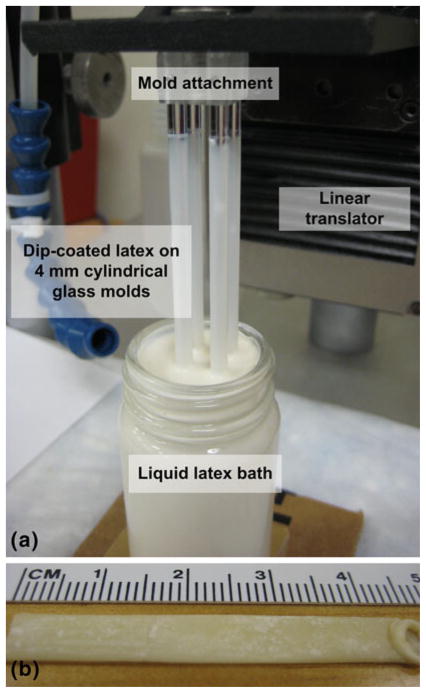
The fabrication of the latex tubes (i.e., thin-walled, cylindrical aneurysm model) was based on the dip-coating technique of Neves-Junior et al. (2006). Four 4-mm-cylindrical glass rods (McMaster-Carr Supply, Co., Atlanta, Georgia) were cleaned and dried with acetone, alcohol, distilled water, and high pressure air. The rods were then mounted in a custom-made fixture that was attached to a steel linear stage (UTM-50CC1DD, Newport Corporation, Irvine, California). The linear stage was then translated with a motion controller (ESP3000, Newport Corporation, Irvine, California) such that the glass molds were vertically introduced into the latex bath at a constant speed of 50 mm/min, as shown in Fig. 4. After dwelling in the latex bath for 30 s, the glass rods were removed at the same speed to ensure a uniform distribution of latex. The dip-coated glass rods were then air-dried for 1–2 min and subsequently cured at 50°C for 20 min in an oven (1510, VWR International LLC, Radnor, Pennsylvania). To increase the thickness of the latex tube, this procedure was repeated 4 more times with a minimum of 20 min provided for curing between each repetition. Before each coating, the latex bath was checked for bubbles and surface coagulations. After the fifth coat was applied, the dip-coated glass rods were cured at room temperature for 24 h.
Fig. 4.
Photographs of a the liquid latex dip-coating system and b a resulting natural rubber latex tube. The primary components of the dip-coating system are four 4-mm glass molds, the attachment to connect the rods to the moveable platform, the linear translator, and the latex bath. A thin-walled latex tube that has been removed from the glass rod is pictured
To neutralize the tacky surfaces of the latex tube, corn starch powder was applied to the cured tube with a soft brush. The tube was then gently removed by hand from the glass rod. Care was taken to prevent excessive stretching of the latex tube and thus maintain the mechanical integrity. After 1 mm of the tube was displaced from the glass rod, the removed section was coated with cornstarch to prevent the tube from sticking to itself. This process continued until the entire inner surface of the tube was coated and removed from the glass mold. The bottom end of the tube where excess latex collected, as shown in Fig. 4b, was removed.
2.4 Dogbone specimens
In addition to forming the cylindrical aneurysm models, the latex was used to fabricate dogbone specimens for characterizing the material properties. First, a polytetrafluorethlylene (PTFE) block (McMaster-Carr Supply, Co., Atlanta, Georgia) was machined using a rapid prototyping mill (MDX-540SA, Roland DGA Corporation, Irvine, California) to have a cavity of 180 mm (L) × 100 mm (W ) × 1 mm (D). The filtered liquid latex was then cast into the PTFE mold and cured in the oven for 24 h at room temperature. After curing, corn starch powder was applied on the surface of the latex sheet. Dogbone specimens were cut using a die (ASTM D-638 Type IV, Pionner-Dietecs Corporation, Weymouth, Massachusetts).
3 Experimental procedures
3.1 Expansion of the SMP foam in the latex aneurysm model
3.1.1 Experimental setup
Figure 5a shows the setup for the latex aneurysm model, which was placed on barbed connectors on each end. The latex tube was secured in place with non-sterile braided silk sutures (DEKNATEL® 2, Teleflex Medical, Inc., Research Triangle Park, North Carolina). The length of the latex tube between the barbed connections was 35 mm, which was the same value for each experiment. Deionized water was injected via a syringe through the aneurysm model to verify there were no leaks and to remove the cornstarch from the inner lining of the latex tube. The cornstarch residue on the outer surface of the latex tube was removed by lightly applying water and then gently wiping with a wet tissue (Kimwipe®, Kimberly-Clark Corporation, Irving, Texas). A micropipette (1B200-6, World Precision Instruments, Inc., Sarasota, Florida) was drawn to a fine-tip through which extracted ink out of a black Sharpie® marker was used to apply the marks used for displacement tracking on the latex aneurysm model. Five groups of dots were applied on the top and along the centerline of the latex tube, as shown in Fig. 5b. Each group of dots consisted of five dots in a square 1-mm grid. The movement of these dots was captured on a camera (ProgRes® CF scan, Jenoptik Optical Systems, Inc., Easthampton, Massachusetts) and microscope (MX16, Leica Microsystems, Inc., Bannockburn, Illinois), which allowed for calculating the 2D displacements of the dots.
Fig. 5.
The cylindrical latex aneurysm model mounting stage. a Photograph of the latex aneurysm model secured to the connectors with sutures. b Schematic diagram of major components of the stage, including the connections to the pressure transducers and tubing, the latex tube, and the markers on the surface of the latex tube
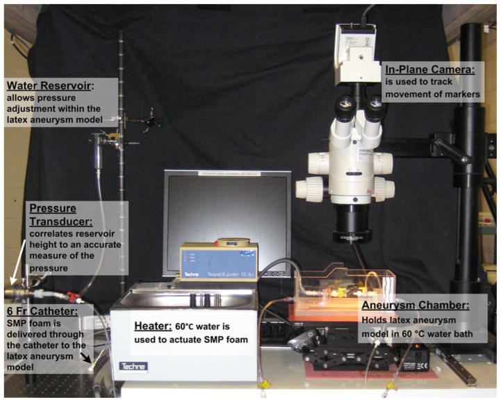
The entire aneurysm model experimental setup is shown in Fig. 6. The aneurysm chamber included the platform for the aneurysm model and the necessary connections. A y-connector was attached to one end of the platform. The y-connector allowed for both controlling the water input and also creating a pathway for the deployment of the compressed foam, which was delivered using a guiding catheter (ENVOY XB 6 Fr, Cordis Neurovascular, Inc., Miami Lakes, Florida). The other end of the platform was connected to a pressure transducer (PX429-2.5G5V, OMEGADYNE Inc., Sunbury, Ohio) that correlated water reservoir height to a measure of the pressure. The water was heated to a temperature of 60°C using a water heater and pump (Tempette Junior TE-8J, Techne, Inc., Princeton, New Jersey), and the heated water was responsible for inducing the shape recovery of the SMP foam.
Fig. 6.
A photograph of the primary components of the experimental system, which consists of: a temperature-controlled aneurysm chamber, a distension system including a static water reservoir, pathways for a 6 Fr catheter pathway and a pressure transducer, and a video system for tracking the motion of markers on the surface of the latex aneurysm model
3.1.2 Protocol for the deployment of the SMP foam
After the temperature of the water in the aneurysm chamber reached 60°C, the aneurysm model was pressurized by slowly increasing the height of the water reservoir that was connected to the pressure transducer. As a result, the pressure in the aneurysm model increased by increments of 3.0–3.8 mmHg. To precondition the aneurysm model, the pressure was increased from 0 mmHg to ~30 mmHg and then back to 0 mmHg. This pressure cycle was repeated ten times.
The temperature of the water in the aneurysm chamber was decreased to room temperature (23°C), and then the crimped SMP foam, attached to a guidewire (Fig. 3), was delivered through the catheter pathway to the center of the aneurysm model. The temperature of the water in the chamber was increased to 60°C, approximately the Tg of the SMP, and the SMP foam attempted to expand to its original shape, which was either 6 or 8 mm diameter. Due to the constraints imposed by the latex aneurysm model, the final diameter of the foam and latex model was less than that of the original, expanded foam. After expansion was complete, the dots were again imaged to determine the resultant displacements from a single image.
3.1.3 Calculation of the strain in the latex aneurysm model
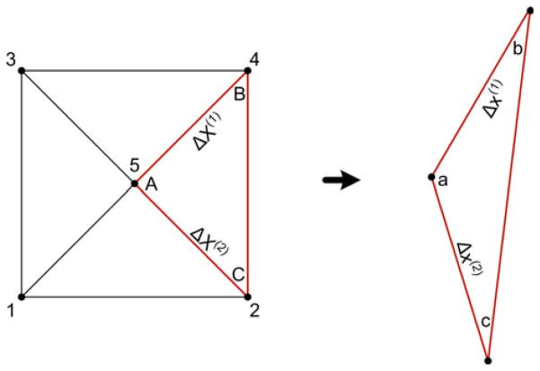
The tracking markers on the surface of the inflating latex aneurysm model were used to calculate the local displacement gradients and in-plane Green strain. As shown in Fig. 7, each set of five dots was decomposed into four similar triangles (Heistand et al. 2005; Humphrey 2002).
Fig. 7.
A set consist of 5 markers subdivided into four triplets (nodes 215, 135, 345, and 425 (highlighted)). The resulting deformation gradients are obtained from the difference of position vectors between the reference and current configurations. For each triplet, points A and a are selected to be at the center of the five-dot system. Adapted from Heistand et al. (2005)
The 2D deformation gradient tensor F was calculated using Eq. 1 (Lai et al. 1993; Heistand et al. 2005) for each triplet by comparing the position vectors in the current (deformed) configuration to the position vectors in the reference (undeformed) configuration. As shown in Fig. 7, the corners of the triplets were labeled with a, b, and c in the current configuration and A, B, and C in the reference configuration. The markers of the triplet were assumed to be close enough to approximate the deformation as homogenous within each marker triplet.
| (1) |
where Δx(1) and Δx(2) were the differences in the current configuration positions of a and b (xb − xa) and a and c (xc − xa), respectively, and ΔX(1) and ΔX(2) were the differences in the reference configuration positions of a and b (Xb − Xa) and a and c (Xc − Xa), respectively. For each triplet, points A and a were taken to coincide with the vertex at the center of the five dots. After calculating the deformation gradient for each triplet, the finite 2D Green strain tensor E was calculated using Eq. 2 (Lai et al. 1993),
| (2) |
where E11 and E22 were the axial and circumferential components, respectively, and E12 and E21 were the shear components of the Green strain.
3.1.4 Estimation of the stress in the latex aneurysm model
The stress was estimated using 3 different methods: (1) physical, experimental estimate, (2) analytical solution, and (3) computational model. In all three methods, the deformation of the latex tube after foam deployment was the independent variable, and the stress required to produce the latex deformation was sought. For the experimental estimate, the latex tube was pressurized incrementally from 0 to 30 mmHg, and Green strains were calculated from the measured deformations. Using a second-degree polynomial fit to the data, the pressures associated with the deformations of the foam deployments were estimated. The pressure values were then used to estimate the circumferential stress (hoop stress), σc, of the latex aneurysm model using the thin-walled, cylindrical pressure vessel formula in Eq. (3),
| (3) |
where p was the pressure estimated from the regression curve, r was the inner radius of the cylindrical aneurysm model, and t was the wall thickness of the latex model.
3.1.5 Constitutive relation for latex model and dogbone tests
For the analytical solution and the computation model, the constitutive relation for latex was needed. We used a Mooney-Rivlin constitutive model with strain energy function:
| (4) |
where C10 and C01 were material-specific coefficients that were estimated from uniaxial testing of the dogbones, IC and IIC were the first and second invariants of C in Eq. (5), and the material was assumed to be incompressible.
| (5) |
The latex dogbones were submerged in a water bath (89032-216, VWR International LLC, Radnor, Pennsylvania) at 60°C for 1 h. Each dogbone was stretched up to 150% of its original length. The preconditioning stretching was repeated ten times to simulate the preconditioning of the cylindrical samples. Tensile tests were performed on the latex dogbones to obtain the material properties that were used in the analytical solution and the finite element simulations. The experiments were performed on a single column, screw-driven, electromechanical tensile tester (Synergie 400, MTS Systems Corporation, Eden Prairie, Minnesota), which was accessorized with a 50 N load cell (SMT1-50N-166, Interface, Inc., Scottsdale, Arizona) and 10 N spring action grips (100-033-242, MTS Systems Corporation, Eden Prairie, Minnesota). The tests were conducted with the specimen and grips inside a water bath (Bionix Mini Bath 685.07, MTS Systems Corporation, Eden Prairie, Minnesota) that was equipped with an additional coil heater to aid in achieving the desired temperature. The procedure for testing each of the three dogbone samples was the following:
Set the load and strain to zero and mount the specimen in the grips.
Fill the water bath and raise the temperature to 60°C. The temperature was measured by a thermocouple that was placed near the center of the latex specimen.
Strain the specimen at a displacement rate of 50 mm/min, which corresponded to the ASTM D638 standard for nonrigid polymers (ASTM Standard D638 2003).
3.2 Analytical solution of the stress in the latex aneurysm model
The inflation and extension of the circular tube with assumed incompressibility was a tractable boundary problem (Humphrey 2002). This problem was solved using the position vectors, in cylindrical coordinates, of the cylindrical tube in the reference (R, Θ, Z) and current (r, θ, z) configurations.
| (6) |
where Λ was the longitudinal stretch per unit unloaded length.
The deformation gradient tensor F for pure inflation and extension is
| (7) |
Enforcing the incompressibility assumption J = det F ≡ 1 led to:
| (8) |
where, r and R were radii in the loaded configuration and the unloaded configuration, respectively, and subscript i represented values corresponding to the inner-wall. The right and left Cauchy-Green strain tensors (C = FTF and B = FFT, respectively) were identical for the diagonal deformation gradient considered, and the result is presented in Eq. (9).
| (9) |
The Cauchy stress was then calculated using Eq. (10).
| (10) |
where p* was the Lagrange multiplier determined from boundary conditions and equilibrium in Eq. (11).
| (11) |
The material properties and values of deformation used as inputs for the analytical equations were obtained from the dogbone tensile tests and cylindrical expansion experiments, respectively. The longitudinal stretch, Λ, was obtained by calculating the change of axial lengths in unloaded and loaded configurations. Table 1 summarizes the values of deformation used as input to the analytical equations.
Table 1.
Input parameters used to calculate the analytical solutions
| Analytical solution | Inner radius, initial (mm) | Outer radius, initial (mm) | Inner radius, final (mm) | Outer radius, final (mm) | Averaged axial stretch, Λ |
|---|---|---|---|---|---|
| 1 | 2.151 | 2.21 | 2.304 | 2.36 | 0.9925 |
| 2 | 2.201 | 2.26 | 2.598 | 2.65 | 0.9660 |
| 3 | 2.211 | 2.27 | 2.384 | 2.44 | 0.9756 |
| 4 | 2.151 | 2.21 | 2.407 | 2.46 | 0.9925 |
| 5 | 2.186 | 2.245 | 2.568 | 2.62 | 0.9660 |
| 6 | 2.106 | 2.165 | 2.299 | 2.335 | 0.9716 |
| 7 | 2.151 | 2.21 | 2.209 | 2.265 | 1.0191 |
| 8 | 2.026 | 2.085 | 2.083 | 2.14 | 1.0021 |
C10 and C01 will be addressed in Table 2
After solving for the Cauchy stress t with deformation values in Table 1 and the parameters in the Mooney-Rivlin coefficients in Table 2, the first Piola-Kirchhoff stress P, which was a 3D generalization of engineering stress, was calculated using Eq. (12).
Table 2.
Material properties and geometries considered for the cylindrical aneurysm finite element model
| (12) |
3.3 Finite element modeling of the cylindrical aneurysm
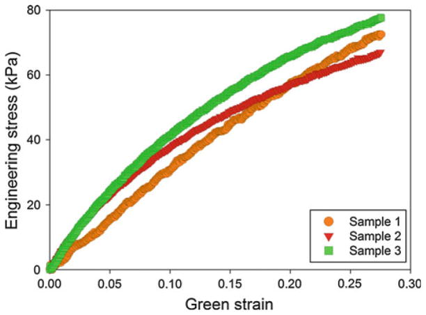
The simulations in this work were performed using ABAQUS® 6.9-EF1 finite element software. The geometry of the model was assumed to be an idealization of the experimental setup. The latex was modeled as an isotropic, 2D cylindrical shell with a length of 20 mm. The thickness of the shell was chosen to be 0.118 mm, which was an average of the thicknesses of the latex samples in the experimental procedure. The material properties of the latex were calculated from the tensile tests performed on the latex dog-bones, of which the results were presented in Fig. 8. Using the ABAQUS® material evaluator, the average Mooney-Rivlin coefficients C10 and C01 were −28.97 and 109.35 kPa.
Fig. 8.
Stress versus Green strain (up to 0.5) for the three latex dog-bone samples tested uniaxially while submerged in water at 60°C. The material response is observed to be repeatable between the three samples to approximately 0.20
The foam was modeled as an isotropic, solid cylinder 10 mm in length and 2 mm in initial outer radius. The expansion of the foam was modeled as a uniform radial displacement imposed on the boundary. This radial displacement was approximated using the outer radius of the latex, measured experimentally, before and after the expansion of the foam. Because the stress in the latex model (and not the foam) was the quantity of interest, the foam was arbitrarily modeled as a linear elastic material with an elastic modulus of 75 kPa.
The latex was modeled using 2D, linear, reduced integration elements (S4R), and the foam was modeled using 3D, linear, hybrid brick elements (C3D8H). The element seed size was selected to be 0.1 for both the latex and the foam, resulting in approximately 3500 and 18000 elements, respectively. The foam was assumed to be at the center of the latex, of which the edges were assumed to be pinned. The nonlinear geometry feature was enabled for the simulation, and the general contact feature was used to accommodate the resulting contact between the foam and the latex. Using symmetrical boundary conditions in each of the three principal directions, only 1/8th of the aneurysm model was simulated.
The finite element model was used to simulate the smallest and largest expansion cases in the 8-mm foam experiments as well as the median expansion cases for each of the four 8-mm foam experiments and the two 6-mm foam experiments. Tables 2 and 3 summarize the parameters for the finite element simulations. Table 2 presents the model geometries and material properties for the cylindrical latex and human aneurysm models. Table 3 presents the experimentally measured outer diameters before and after expansion and the resulting radial displacements for the foam for each case considered.
Table 3.
Boundary conditions used as input to the finite element simulations
| Simulation | Outer radius (latex), initial (mm) | Outer radius (foam + latex), final (mm) | Radial displacement, foam (mm) | Equivalent contact pressure (kPa)a |
|---|---|---|---|---|
| 1 | 2.21 | 2.36 | 0.242 | 1.9 |
| 2 | 2.26 | 2.65 | 0.532 | 3.53 |
| 3 | 2.27 | 2.44 | 0.322 | 1.95 |
| 4 | 2.21 | 2.46 | 0.342 | 2.75 |
| 5 | 2.245 | 2.62 | 0.502 | 3.5 |
| 6 | 2.165 | 2.335 | 0.237 | 2.3 |
| 7 | 2.21 | 2.265 | 0.147 | 0.75 |
| 8 | 2.085 | 2.14 | 0.022 | 0.82 |
The equivalent contact pressure is the pressure the foam exerts on the latex aneurysm model, and these values are used as input to the human aneurysm model
After simulating the foam expansion experiments in the latex system, the finite element model was used to predict the stresses that would result upon deployment of the shape memory polymer foam inside a human aneurysm. The initial radius of the simplified cylindrical aneurysm was assumed to be equal to that of the latex system (2 mm), but the thickness was modified to be 0.0278 mm, which was assumed to be a reasonable minimum value for a saccular aneurysm (Kyriacou and Humphrey 1996; Scott et al. 1972; Stehbens 1990; Suzuki and Ohara 1978). The aneurysm was then modeled as a linear elastic material with a modulus of 1700 kPa, which is an average value for the elastic modulus at the aneurysm fundus (Steiger et al. 1989). Rather than using the radial expansion of the foam measured in the latex experiments, the foam expansion was simulated as an applied pressure. The pressures used for these predictions were the contact pressures calculated in the foam and latex simulations. The contact pressure was the pressure that the foam exerted on the latex during expansion and was assumed to be a representation of the tendency of the foam to return to its original, expanded shape. As a result, the contact pressure was assumed to be the same value for both the latex or aneurysm systems and considered to be a more reasonable input to the aneurysm model predictions than the radial displacements measured in the latex experiments, which were dependent on the compliance and thickness of the cylindrical shell. The pressure values used for each of the eight predictions are presented as the equivalent contact pressure in Table 3.
4 Results
4.1 Calibration of pressure versus strain
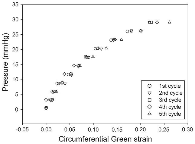
Figure 9 presents the results for a test in which the latex model was inflated to pressures of 0 to 30 mmHg for five cycles. The data shown represent one triplet of the center of the five groups (five nodes/marks per group). After preconditioning the sample (inflation and deflation) ten times, no correlation of the calculated circumferential strains with the cycle number is observed. Figure 9 indicates that the Green strain of a particular marker triplet is repeatable for each of the five cycles. The standard deviation of the circumferential strain varies exponentially from 0.001 at 0 mmHg to 0.033 at 30 mmHg for each nominal value of pressure.
Fig. 9.
Five inflation cycles of a preconditioned latex aneurysm mode. The pressure versus Green strain in the circumferential direction is presented for each inflation cycle
4.2 Estimation of the stress in the latex aneurysm model
Cylindrical SMP foams, with original (uncrimped) diameters of 6 and 8 mm, were deployed inside a latex aneurysm model that had an initial inner diameter of 4 mm. As the water was heated to 60°C to deploy the foam, the latex tube was also heated and became more compliant, which allowed the latex to better conform to the shape of the expanding foam. Figure 10 presents the Green strains and estimated circumferential stresses, using thin-walled, cylindrical pressure theory, for six experiments. Experiments 1–4 correspond to SMP foam samples with uncrimped diameters of 8 mm, and experiments 5–6 correspond to SMP foam samples with uncrimped diameters of 6 mm. Each of the five experimental data points represents the average value from the four triplets that comprise set of markers.
Fig. 10.
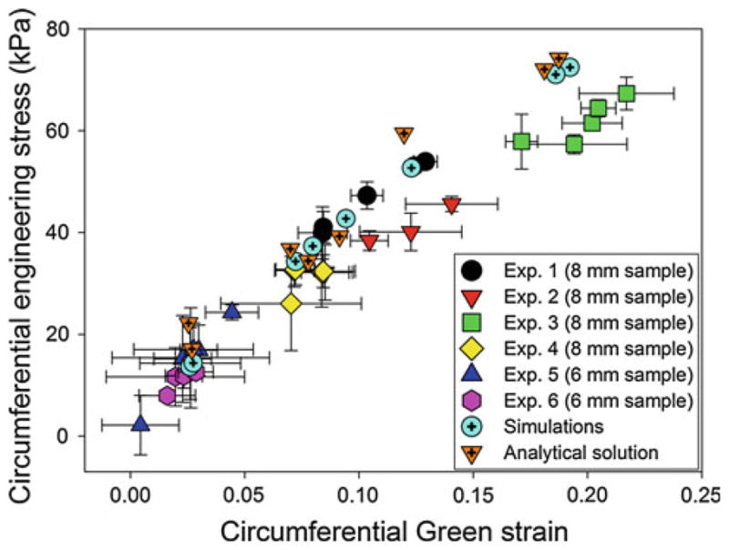
Circumferential stress versus circumferential strain for the analytical theory, simulations, and experimental data
With the exception of experiment 2, the data from each experiment show no correlation of the pressure and strain with the location of marker sets. The maximum stress from experiments 1, 3, and 4 is 67.3 kPa at a strain of 0.22 and minimum stress is 26.04 kPa at a strain of 0.07. In these three experiments, all markers were located in the middle of the foam expansion region. Experiment 2, on the other hand, analyzed the circumferential strains near one end of expanded SMP foam, and the maximum stress is 45.59 kPa at a strain of 0.14. The minimum stress is 15.38 kPa at a strain of 0.03. For the 6 mm SMP foams (experiments 5 and 6), the maximum stress is 24.3 kPa at a strain of 0.04 and the minimum stress is 2.15 kPa at a strain of 0.004. For all 6- and 8-mm foams, the pressure resulting from the expansion of foams is measured experimentally to be less than 10 mmHg (6-mm foams) to 30 mmHg (8-mm foams).
The difference in the stress and strain values for SMP foam samples of the same size is likely due to the heterogeneity of the foam (e.g., difference in pore cell sizes, anisotropy, etc.). As a result, the SMP foams may not be expanded uniformly inside of the latex aneurysm model, and thus, the stress distribution in each experiment might vary between each contact point (marker set) between the SMP foams and the latex aneurysm model.
4.3 Analytical solution of the stress in the latex aneurysm model
The results from analytical solution for the stress exerted by the foam expansion in the latex aneurysm model are presented in Fig. 10. In this figure, the circumferential stresses are presented for the smallest and largest strains in the 8-mm foam expansion experiments as well as the median strain cases for each of the 6- and 8-mm experiments. The difference in the stresses estimated using thin-walled, cylindrical pressure theory and the analytical equations is due to the Poisson effect, which becomes non-negligible for large expansions, and is captured by the analytical solution but not by the thin-walled, cylindrical pressure theory. Specifically, for expansions resulting in large circumferential strains, the contraction of the aneurysm in the longitudinal direction results in an increase in the circumferential stress, which is captured in the analytical solutions through the variable Λ.
4.4 Finite element modeling
4.4.1 Cylindrical latex aneurysm experiments simulations
The results from simulating the foam expansion in the latex aneurysm model are presented in Fig. 10. In this figure, the circumferential stress values are presented for the smallest and largest strains in the 8-mm foam expansion experiments as well as the median strain cases for each of the 6- and 8-mm experiments. The results for the circumferential stress in the shell are compared to the stresses estimated from the experiments. It is observed that the finite element simulations have reasonable agreement with the values calculated from both the thin-walled, cylindrical pressure theory and the analytical solutions and capture well the nonlinear stress versus strain behavior. The differences between the finite element simulations and the analytical solutions in the circumferential stresses and circumferential Green strains are 2.311 ± 4.175 (kPa) and 0.003 ± 0.002, respectively. The slight differences are primarily a result of the differences in input parameters to the analytical equations and finite element simulations. In the analytical solutions, both the longitudinal stretch and change in outer diameter, estimated from the experimentally acquired images, are used as inputs. On the other hand, the finite element simulations use the change in the final outer diameter as input and the longitudinal stretch is handled through the incompressibility condition.
4.4.2 Cylindrical human aneurysm predictions
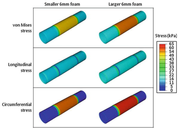
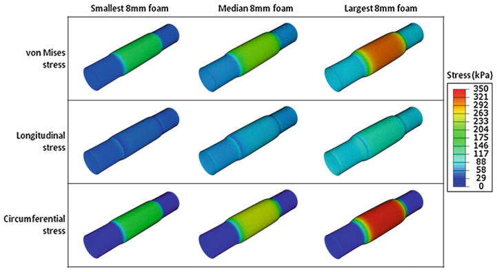
In Figs. 11, 12, 13, the predictions for the stress and strain of a cylindrical human aneurysm with reasonable material properties are presented. In Fig. 11, the stress versus strain behavior is presented for the range of pressures corresponding to the 6- and 8-mm foam expansion experiments. The stresses predicted for the human aneurysm are higher than those simulated for the latex aneurysm model because the human aneurysm has a smaller thickness (0.0278 mm) compared to the latex (0.118 mm) and because the linear elastic modulus of the human aneurysm is higher than the modulus of the latex. In addition, Fig. 12 presents the contour plots for the two 6-mm foam expansion cases. The maximum circumferential stress is observed in the larger expansion case (right), and the maximum value is approximately 65 kPa. In Fig. 13, the smallest, median, and largest 8-mm foam expansion cases in the first, second, and third columns, respectively. The hoop stresses, axial stresses, and resulting von Mises stresses in the cylindrical aneurysm are presented in the first, second, and third rows, respectively.
Fig. 11.
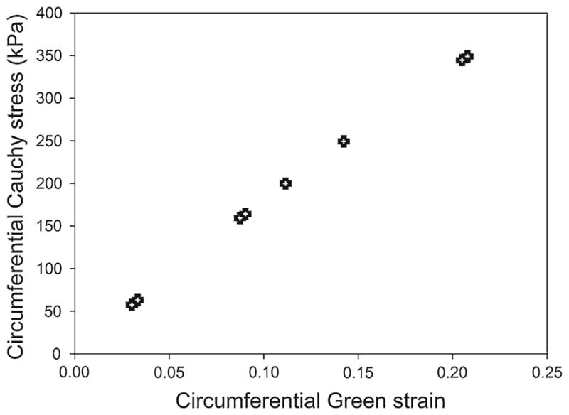
Finite element predictions for the cylindrical stress versus cylindrical strain in a cylindrical human aneurysm that has a thickness of 0.0278 mm and an elastic modulus of 1700 kPa. The input pressures used in these simulations are the results of the latex simulations shown in Fig. 10
Fig. 12.
Predictions in the aneurysm wall for the stresses in the two 6-mm foam expansion cases. The smaller and larger of the two expansions are presented in the left and right columns, respectively. The von Mises, longitudinal, and circumferential stresses are presented in the first, second, and third rows, respectively. All contours are presented with respect to the same scale, which has a maximum of 65 kPa
Fig. 13.
Predictions in the aneurysm wall for the stresses in three 8-mm foam expansions. The smallest, median, and largest 8-mm foam deployments are presented in the first, second, and third columns, respectively. The von Mises, longitudinal, and circumferential stresses are presented in the first, second, and third rows, respectively. All contours are presented with respect to the same scale, which has a maximum of 350 kPa
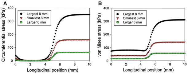
In addition, the spatial variation of the stresses with respect to position can be obtained from the finite element analyses. In Fig. 14a, b, the circumferential stresses and von Mises stresses are presented, respectively, with respect to the longitudinal position for the largest 8-mm foam, the smallest 8-mm foam, and the larger 6-mm foam. In these analyses, the cylindrical aneurysm was longitudinally and radially constrained at 0 mm, the symmetrical boundary conditions were applied at 10 mm, and the equivalent pressure used to model the foam expansion was radially applied from 5 mm to 10 mm. From Fig. 14, it is observed the stresses are at a maximum from approximately 7–10 mm—the central portions of the foam expansion. The stresses then decrease near the edge of the foam expansion, with the circumferential stress decreasing to approximately zero at a position of 3 mm, and the von Mises stress reaching an approximately constant value at 4 mm. This constant value ranges from 15 to 80 kPa for the larger 6-mm foam and the largest 8-mm foam cases, respectively, and is primarily a result of stretching in the longitudinal direction.
Fig. 14.
Predictions of the a circumferential and b von Mises stresses in a cylindrical human aneurysm for the largest 8-mm foam, the smallest 8-mm foam, and the larger 6-mm foam cases. The foam expansion is modeled as an equivalent radial pressure, applied from a longitudinal position of 5–10 mm. The aneurysm is constrained longitudinally and radially at 0 mm and symmetrical boundary conditions are enforced at 10 mm
5 Discussion
This study presented a deployment of oversized SMP foam to embolize an aneurysm. The foam, either 150 or 200% oversized compared to the diameter of the latex aneurysm model, was deployed in-vitro, and the displacements of the applied marker dots were used to estimate the strains in the latex, which was 0.118 mm thick.
The stresses in the latex resulting from the foam expansion, estimated using thin-walled, cylindrical pressure theory, an analytical solution, and finite element simulations were all in good agreement with each other. The finite element model extended to predict the stresses in a human aneurysm considered a worst case scenario of an aneurysm wall with a reasonable minimum thickness, 1.5 and 2 times oversized embolization, and linear elastic material properties for the aneurysm wall. The maximum circumferential stress predicted in these simulations was 350 kPa at a circumferential Green strain of 0.21, which was still well below threshold wall breaking stress the minimum wall breaking stresses of 700 kPa (Humphrey and Na 2002; MacDonald et al. 2000).
A Mooney-Rivlin material model is ill-conceived for the determination of material response functions for latex because of a degeneracy, wherein there are many representations with the same response (Criscione 2003). However, the degeneracy of representations based on W (I1, I2) is inconsequential for our application, a forward solution. This material model is well-recognized as one that gives accurate results for the stresses in rubber-like materials undergoing moderate strain.
It is noteworthy that this study uses a cylindrical aneurysm model instead of a spherical model, which is considered a better representation of the real human aneurysm. While providing for a simplification in the study, the cylindrical model also allows for the worst case for the circumferential stresses generated in the model from the expanding foam. The circumferential stresses of a spherical latex aneurysm using the thin-walled spherical pressure vessel can be written as , where, p is pressure, r is radius, and t is thickness. From Eq. 3, σs for a spherical geometry is a half of the circumferential stresses of a cylindrical latex aneurysm. Therefore, for the same pressure exerted by the expanding foam, circumferential stresses generated in the cylindrical geometry will be higher than the spherical, giving the worst case for aneurysm rupture in cylindrical model. Human aneurysms however are generally of very complex geometries ranging from small spherical to large fusiform shapes. For better estimation of biomechanics of human aneurysm in future studies, it may be useful to consider both multiaxial mechanical data of real aneurysm tissue and a realistic geometry in modeling.
The results here indicate that SMP foam samples 1.5–2 times the size of aneurysm can be safely implanted in the aneurysm without a risk of rupture, thereby providing a high packing volume in the treatment. While this result is promising in itself, there are several other details for an effective translation of this concept into clinical practice that are worth discussing:
Foam shape
If a SMP foam is deployed in an aneurysm, there is a possibility of the SMP to protrude into the vessel lumen. There are two general ways to overcome this risk: constrain the foam geometry and constrain expansion. Constraining geometry refers to limiting the foams geometry such that it does not expand into the parent vessel. One example of geometry constraint is mounting the foam on a wire or coil backbone similar to current embolic coil designs. If the foam is limited to radial expand by 1 mm, placing the hybrid device in an aneurysm with a 2-mm-long neck would minimize the risk of the foam protruding into the parent vessel. A second example of geometric constraint would be to produce foam spheroids with machined concave indentations that would limit foam expansion into the parent vessel. Constrained expansion is the use of a temporary or permanent mechanical constraint to limit the foam protrusion into the parent vessel. Placing the foam through a stent wall would result in the stent constraining the foam expansion. The use of stent-assisted SMP foam device has been reported in an earlier study for a fusiform aneurysm model (Small et al. 2007). Even though an oversized packing with SMP foam was not performed in the former study, a neurovascular stent-assisted SMP foam deployment may be possible for treating wide neck or fusiform aneurysms.
Flexibility
It is a challenge for the embolic device (crimped SMP foam and delivery device) to be navigated through tortuous vascular pathways such as the carotid siphon. For this reason, a 3-point bending experiment was run to measure the flexural moduli (moduli of elasticity in bending) of the crimped SMP foam (1.15 ± 0.05 mm diameter), 5 Fr guiding catheter (ENVOY 5 Fr, Cordis Neurovascular, Inc., Miami Lakes, Florida), and 1.7 Fr micro catheter (PROWLER-10, Cordis Neurovascular, Inc., Miami Lakes, Florida), and the results were 79.60 ± 26.90, 182.78 ± 16.16, and 76.65 ± 5.95 MPa, respectively (n = 5 in all cases). Because the modulus of the crimped SMP foam is less than half of the 5 Fr guiding catheter, the SMP foam will be easy to navigate within the catheter. Even if the modulus of the microcatheter is similar to that of the crimped SMP, we believe that less material volume and a surface modification of the crimped SMP foam will allow flexibility in navigating tortuous pathways.
Actuation
These thermally actuated shape memory foams require heat energy to come to their expanded primary shape from a crimped secondary shape. In this study, we use 60°C water as a thermal source because latex is an elastomer whose mechanical properties can get changed with temperature changes, and with a uniform water bath, it was possible to characterize the mechanical properties of latex repeatably under this condition. In clinical practice, a radiative energy source at the distal end of the delivery device could be used to actuate the SMP to the primary, recovered shape (Maitland et al. 2007; Ortega et al. 2007).
6 Conclusion
This study established an experimental method of estimating the forces applied by a low-modulus SMP foam on the aneurysm wall during expansion. Thin-walled, cylindrical latex models custom-made via dip coating were used for allowing measurement of low strains from the foams, and calculation of stresses was done using the thin wall pressure vessel theory, an analytical solution, and finite element modeling. The experimental results were used with finite element modeling to predict stresses generated in a human aneurysm in the worst case scenario of a minimum thickness, 1.5 and 2 times oversized embolization, and linear elastic material properties for the cylindrical aneurysm wall.
It is predicted that a 1.5 times oversized foam (e.g., 6-mm foam in a 4-mm aneurysm) can be deployed and result in a maximum circumferential stress of 65 kPa, which is less than 1/10th of the minimum wall breaking stress of 700 kPa. In addition, the expansion of 6-mm foam is measured to exert a pressure of less than 10 mmHg, which is not expected to pose a significant additional risk to the existing physiological condition of patients.
In conclusion, the use of oversized SMP foam as embolic devices can promote a more complete filling of an aneurysm while generating stresses that are well below the threshold that may cause the aneurysm wall to break. Thus, these foams may present reduced risk of rupture resulting from the embolic implant compared to microcoils.
Acknowledgments
This work was supported by the National Institutes of Health/National Institute of Biomedical Imaging and Bioengineering Grant R01EB000462. Funding for the work of B.L. Volk was provided by the National Defense Science and Engineering Graduate (NDSEG) Fellowship. The authors would also like to acknowledge Jaewon Park for measuring latex thicknesses.
Contributor Information
Wonjun Hwang, Department of Biomedical Engineering, Texas A&M University, MS 3120, 5045 Emerging Technologies Building, College Station, TX, 77843-3120, USA.
Brent L. Volk, Department of Biomedical Engineering, Texas A&M University, MS 3120, 5045 Emerging Technologies Building, College Station, TX, 77843-3120, USA. Materials Science and Engineering Program, Texas A&M University, MS 3003, 412 ENPO Building, College Station, TX, 77843-3003, USA
Farida Akberali, Department of Biomedical Engineering, Texas A&M University, MS 3120, 5045 Emerging Technologies Building, College Station, TX, 77843-3120, USA.
Pooja Singhal, Department of Biomedical Engineering, Texas A&M University, MS 3120, 5045 Emerging Technologies Building, College Station, TX, 77843-3120, USA. Chemical Sciences Division, Physical and Life Sciences, Lawrence Livermore National Laboratory, Livermore, CA, 94550, USA.
John C. Criscione, Department of Biomedical Engineering, Texas A&M University, MS 3120, 5045 Emerging Technologies Building, College Station, TX, 77843-3120, USA
Duncan J. Maitland, Email: djmaitland@tamu.edu, Department of Biomedical Engineering, Texas A&M University, MS 3120, 5045 Emerging Technologies Building, College Station, TX, 77843-3120, USA. Materials Science and Engineering Program, Texas A&M University, MS 3003, 412 ENPO Building, College Station, TX, 77843-3003, USA
References
- Abruzzo T, Shengelaia GG, Dawson RC, III, Owens DS, Cawley CM, Gravanis MB. Histologic and morphologic comparison of experimental aneurysms with human intracranial aneurysms. Am J Neuroradiol. 1998;19(7):1309–1314. [PMC free article] [PubMed] [Google Scholar]
- Ahuja AA, Hergenrother RW, Strother CM, Rappe AA, Cooper SL, Graves VB. Platinum coil coatings to increase thrombogenicity—a preliminary-study in rabbits. Am J Neuroradiol. 1993;14(4):794–798. [PMC free article] [PubMed] [Google Scholar]
- Akkas N. Aneurysms as a biomechanical instability problem. In: Mosora F, editor. Biomechanical transport processes. Plenum Press; New York: 1990. pp. 303–311. [Google Scholar]
- Appelboom G, Kadri K, Hassan F, Leclerc X. Infectious aneurysm of the cavernous carotid artery in a child treated with a new-generation of flow-diverting stent graft: case report. Neurosurgery. 2010;66(3):E623–E624. doi: 10.1227/01. NEU.0000365370.82554.08. discussion E624. [DOI] [PubMed] [Google Scholar]
- ASTM Standard D638. ASTM International. 2003. Standard test method for tensile properties of plastics; pp. 1–15. [DOI] [Google Scholar]
- Austin GM, Schievink W, Williams R. Controlled pressure-volume factors in the enlargement of intracranial aneurysms. Neurosurgery. 1989;24(5):722–730. doi: 10.1227/00006123-198905000-00011. [DOI] [PubMed] [Google Scholar]
- Bendszus M, Bartsch AJ, Solymosi L. Endovascular occlusion of aneurysms using a new bioactive coil: a matched pair analysis with bare platinum coils. Stroke. 2007;38(10):2855–2857. doi: 10.1161/STROKEAHA.107.489088. [DOI] [PubMed] [Google Scholar]
- Biondi A, Janardhan V, Katz JM, Salvaggio K, Riina HA, Gobin YP. Neuroform stent-assisted coil embolization of wide-neck intracranial aneurysms: strategies in stent deployment and mid-term follow-up. Neurosurgery. 2007;61(3):460–468. doi: 10.1227/01.NEU.0000290890.62201.A9. discussion 468–469. [DOI] [PubMed] [Google Scholar]
- Brilstra EH, Rinkel GJ, van der Graaf Y, van Rooij WJ, Algra A. Treatment of intracranial aneurysms by embolization with coils: a systematic review. Stroke. 1999;30(2):470–476. doi: 10.1161/01.str.30.2.470. [DOI] [PubMed] [Google Scholar]
- Brisman JL, Niimi Y, Song JK, Berenstein A. Aneurysmal rupture during coiling: low incidence and good outcomes at a single large volume center. Neurosurgery. 2005;57(6):1103–1109. doi: 10.1227/01.neu.0000185631.20246.1a. discussion 1103–1109. 00006123-200512000-00005. [DOI] [PubMed] [Google Scholar]
- Brisman JL, Song JK, Newell DW. Cerebral aneurysms. N Engl J Med. 2006;355(9):928–939. doi: 10.1056/NEJMra052760. [DOI] [PubMed] [Google Scholar]
- Cabanlit M, Maitland D, Wilson T, Simon S, Wun T, Gershwin ME, Van de Water J. Polyurethane shape-memory polymers demonstrate functional biocompatibility in vitro. Macromol Biosci. 2007;7(1):48–55. doi: 10.1002/mabi.200600177. [DOI] [PubMed] [Google Scholar]
- Cekirge HS, Saatci I, Ozturk MH, Cil B, Arat A, Mawad M, Ergungor F, Belen D, Er U, Turk S, Bavbek M, Sekerci Z, Beskonakli E, Ozcan OE, Ozgen T. Late angiographic and clinical follow-up results of 100 consecutive aneurysms treated with Onyx reconstruction: largest single-center experience. Neuroradiology. 2006;48(2):113–126. doi: 10.1007/s00234-005-0007-6. [DOI] [PubMed] [Google Scholar]
- Choudhari KA, Flynn PA, McKinstry SC. Spontaneous extrusion of guglielmi detachable coils from anterior communicating artery aneurysm. Neurol India. 2007;55(2):148–150. doi: 10.4103/0028-3886.32787. [DOI] [PubMed] [Google Scholar]
- Cloft HJ, Kallmes DF. Cerebral aneurysm perforations complicating therapy with Guglielmi detachable coils: a meta-analysis. Am J Neuroradiol. 2002;23(10):1706–1709. [PMC free article] [PubMed] [Google Scholar]
- Criscione JC. Rivlin’s representation formula is ill-conceived for the determination of response functions via biaxial testing. J Elasticity. 2003;70(1–3):129–147. [Google Scholar]
- David G, Humphrey JD. Further evidence for the dynamic stability of intracranial saccular aneurysms. J Biomech. 2003;36(8):1143–1150. doi: 10.1016/s0021-9290(03)00083-6. S0021929003000836. [DOI] [PubMed] [Google Scholar]
- Ferguson GG. Physical factors in the initiation, growth, and rupture of human intracranial saccular aneurysms. J Neurosurg. 1972;37(6):666–677. doi: 10.3171/jns.1972.37.6.0666. [DOI] [PubMed] [Google Scholar]
- Fiorella D, Albuquerque FC, Woo H, Rasmussen PA, Masaryk TJ, McDougall CG. Neuroform instent stenosis: incidence, natural history, and treatment strategies. Neurosurgery. 2006;59(1):34–42. doi: 10.1227/01.NEU.0000219853.56553.71. discussion 34–42. [DOI] [PubMed] [Google Scholar]
- Fiorella D, Kelly ME, Albuquerque FC, Nelson PK. Curative reconstruction of a giant midbasilar trunk aneurysm with the pipeline embolization device. Neurosurgery. 2009;64(2):212–217. doi: 10.1227/01.NEU.0000337576.98984.E4. discussion 217. [DOI] [PubMed] [Google Scholar]
- Fiorella D, Woo HH, Albuquerque FC, Nelson PK. Definitive reconstruction of circumferential, fusiform intracranial aneurysms with the pipeline embolization device. Neurosurgery. 2008;62(5):1115–1120. doi: 10.1227/01.neu.0000325873. 44881.6e. discussion 1120–1111. [DOI] [PubMed] [Google Scholar]
- Gaba RC, Ansari SA, Roy SS, Marden FA, Viana MA, Malisch TW. Embolization of intracranial aneurysms with hydrogel-coated coils versus inert platinum coils: effects on packing density, coil length and quantity, procedure performance, cost, length of hospital stay, and durability of therapy. Stroke. 2006;37(6):1443–1450. doi: 10.1161/01.STR.0000221314.55144.0b. [DOI] [PubMed] [Google Scholar]
- Geyik S, Ertugrul O, Yavuz K, Geyik P, Saatci I, Cekirge HS. Comparison of bioactive coils and bare platinum coils for treatment of intracranial aneurysms: a matched-pair analysis. J Neurosurg. 2010;112(4):709–713. doi: 10.3171/2009.8.JNS081372. [DOI] [PubMed] [Google Scholar]
- Gunnarsson T, Tong FC, Klurfan P, Cawley CM, Dion JE. Angiographic and clinical outcomes in 200 consecutive patients with cerebral aneurysm treated with hydrogel-coated coils. Am J Neuroradiol. 2009;30(9):1657–1664. doi: 10.3174/ajnr.A1691. [DOI] [PMC free article] [PubMed] [Google Scholar]
- Heistand MR, Pedrigi RM, Delange SL, Dziezyc J, Humphrey JD. Multiaxial mechanical behavior of the porcine anterior lens capsule. Biomech Model Mechanobiol. 2005;4(2–3):168–177. doi: 10.1007/s10237-005-0073-z. [DOI] [PubMed] [Google Scholar]
- Henkes H, Fischer S, Weber W, Miloslavski E, Felber S, Brew S, Kuehne D. Endovascular coil occlusion of 1811 intracranial aneurysms: early angiographic and clinical results. Neurosurgery. 2004;54(2):268–280. doi: 10.1227/01.neu.0000103221.16671.f0. discussion 280–265. [DOI] [PubMed] [Google Scholar]
- Hirsch JA, Bendok BR, Paulsen RD, Cognard C, Campos J, Cronqvist M. Midterm clinical experience with a complex-shaped detachable platinum coil system for the treatment of cerebral aneurysms: Trufill DCS Orbit detachable coil system registry interim results. J Vasc Interv Radiol. 2007;18(12):1487–1494. doi: 10. 1016/j.jvir.2007.07.020. [DOI] [PubMed] [Google Scholar]
- Horowitz M, Samson D, Purdy P. Does electrothrombosis occur immediately after embolization of an aneurysm with Guglielmi detachable coils? Am J Neuroradiol. 1997;18(3):510–513. [PMC free article] [PubMed] [Google Scholar]
- Humphrey JD. Cardiovascular solid mechanics: cells, tissues, and organs. Springer; New York: 2002. [Google Scholar]
- Humphrey JD, Na S. Elastodynamics and arterial wall stress. Ann Biomed Eng. 2002;30(4):509–523. doi: 10.1114/1.1467676. [DOI] [PubMed] [Google Scholar]
- Hung EJ, Botwin MR. Mechanics of rupture of cerebral saccular aneurysms. J Biomech. 1975;8(6):385–392. doi: 10.1016/0021-9290(75)90074-3. [DOI] [PubMed] [Google Scholar]
- Ionita CN, Paciorek AM, Dohatcu A, Hoffmann KR, Bednarek DR, Kolega J, Levy EI, Hopkins LN, Rudin S, Mocco JD. The asymmetric vascular stent: efficacy in a rabbit aneurysm model. Stroke. 2009;40(3):959–965. doi: 10.1161/STROKEAHA.108.524124. [DOI] [PMC free article] [PubMed] [Google Scholar]
- Ionita CN, Paciorek AM, Hoffmann KR, Bednarek DR, Yamamoto J, Kolega J, Levy EI, Hopkins LN, Rudin S, Mocco J. Asymmetric vascular stent: feasibility study of a new low-porosity patch-containing stent. Stroke. 2008;39(7):2105–2113. doi: 10.1161/STROKEAHA.107.503862. [DOI] [PMC free article] [PubMed] [Google Scholar]
- Kallmes DF, Borland MK, Cloft HJ, Altes TA, Dion JE, Jensen ME, Hankins GR, Helm GA. In vitro proliferation and adhesion of basic fibroblast growth factor-producing fibroblasts on platinum coils. Radiology. 1998;206(1):237–243. doi: 10.1148/radiology.206.1.9423678. [DOI] [PubMed] [Google Scholar]
- Kallmes DF, Ding YH, Dai D, Kadirvel R, Lewis DA, Cloft HJ. A new endoluminal, flow-disrupting device for treatment of saccular aneurysms. Stroke. 2007;38(8):2346–2352. doi: 10.1161/STROKEAHA.106.479576. [DOI] [PubMed] [Google Scholar]
- Kallmes DF, Williams D, Cloft HJ, Lopes MBS, Hankins GR, Helm GA. Platinum coil-mediated implantation of growth factor-secreting endovascular tissue grafts: an in vivo study. Radiology. 1998;207(2):519–523. doi: 10.1148/radiology.207.2.9577504. [DOI] [PubMed] [Google Scholar]
- Kyriacou SK, Humphrey JD. Influence of size, shape and properties on the mechanics of axisymmetric saccular aneurysms. J Biomech. 1996;29(8):1015–1022. doi: 10.1016/0021-9290(96)00010-3. 0021929096000103. [DOI] [PubMed] [Google Scholar]
- Lai WM, David Rubin, Erhard Krempl. Introduction to continuum mechanics. 3. Butterworth-Heinemann; Woburn: 1993. [Google Scholar]
- Leonardi M, Dall’olio M, Princiotta C, Simonetti L. Treatment of carotid siphon aneurysms with a microcell stent. A case report. Interv Neuroradiol. 2008;14(4):429–434. doi: 10.1177/159101990801400408. IN.v14.i4.p429. [DOI] [PMC free article] [PubMed] [Google Scholar]
- Liang G, Gao X, Li Z, Wei X, Xue H. Neuroform stent-assisted coiling of intracranial aneurysms: a 5 year single-center experience and follow-up. Neurol Res. 2010;32(7):721–727. doi: 10.1179/016164109X12445616596409. [DOI] [PubMed] [Google Scholar]
- Lubicz B, Bandeira A, Bruneau M, Dewindt A, Baleriaux D, De Witte O. Stenting is improving and stabilizing anatomical results of coiled intracranial aneurysms. Neuroradiology. 2009;51(6):419–425. doi: 10.1007/s00234-009-0519-6. [DOI] [PubMed] [Google Scholar]
- Lylyk P, Miranda C, Ceratto R, Ferrario A, Scrivano E, Luna HR, Berez AL, Tran Q, Nelson PK, Fiorella D. Curative endovascular reconstruction of cerebral aneurysms with the pipeline embolization device: the Buenos Aires experience. Neurosurgery. 2009;64(4):632–642. doi: 10.1227/01. NEU.0000339109.98070.65. discussion 642–633; quiz N636. [DOI] [PubMed] [Google Scholar]
- MacDonald DJ, Finlay HM, Canham PB. Directional wall strength in saccular brain aneurysms from polarized light microscopy. Ann Biomed Eng. 2000;28(5):533–542. doi: 10.1114/1.292. [DOI] [PubMed] [Google Scholar]
- Maitland DJ, Small WIV, Ortega JM, Buckley PR, Rodriguez J, Hartman J, Wilson TS. Prototype laser-activated shape memory polymer foam device for embolic treatment of aneurysms. J Biomed Opt. 2007;12(3):030504. doi: 10.1117/1.2743983. [DOI] [PubMed] [Google Scholar]
- Maitland DJ, Small WIV, Singhal P, Hwang W, Rodriguez JN, Clubb F, Wilson TS. Design and realization of biomedical devices based on shape memory polymers. Mater Res Soc. 2009;1190(NN06):1–13. [Google Scholar]
- Molyneux AJ, Cekirge S, Saatci I, Gal G. Cerebral aneurysm multicenter european onyx (CAMEO) trial: results of a prospective observational study in 20 European centers. Am J Neuroradiol. 2004;25(1):39–51. [PMC free article] [PubMed] [Google Scholar]
- Murayama Y, Nien YL, Duckwiler G, Gobin YP, Jahan R, Frazee J, Martin N, Vinuela F. Guglielmi detachable coil embolization of cerebral aneurysms: 11 years’ experience. J Neurosurg. 2003;98(5):959–966. doi: 10.3171/jns.2003.98.5.0959. [DOI] [PubMed] [Google Scholar]
- Murayama Y, Vinuela F, Suzuki Y, Akiba Y, Ulihoa A, Duckwiler GR, Gobin YP, Vinters HV, Iwaki M, Abe T. Development of the biologically active Guglielmi detachable coil for the treatment of cerebral aneurysms. Part II: an experimental study in a swine aneurysm model. Am J Neuroradiol. 1999;20(10):1992–1999. [PMC free article] [PubMed] [Google Scholar]
- Murayama Y, Vinuela F, Tateshima S. Matrix: new bio-absorbable polymeric coils for the treatment of intracranial aneurysms. Int Congr Ser. 2002;1247:119–126. S0531-5131(02)01039-7. [Google Scholar]
- Neves-Junior WFP, Ferreira M, Alves MCO, Graeff CFO, Mulato M, Coutinho-Netto J, Bernardes MS. Influence of fabrication process on the final properties of natural-rubber latex tubes for vascular prosthesis. Braz J Phys. 2006;36(2B):586–591. [Google Scholar]
- Ortega J, Maitland D, Wilson T, Tsai W, Savas O, Saloner D. Vascular dynamics of a shape memory polymer foam aneurysm treatment technique. Ann Biomed Eng. 2007;35(11):1870–1884. doi: 10. 1007/s10439-007-9358-y. [DOI] [PubMed] [Google Scholar]
- Piske RL, Kanashiro LH, Paschoal E, Agner C, Lima SS, Aguiar PH. Evaluation of Onyx HD-500 embolic system in the treatment of 84 wide-neck intracranial aneurysms. Neurosurgery. 2009;64(5):E865–E875. doi: 10.1227/01.NEU.0000340977.68347.51. discussion E875. [DOI] [PubMed] [Google Scholar]
- Schievink WI. Intracranial aneurysms. N Engl J Med. 1997;336(1):28–40. doi: 10.1056/NEJM199701023360106. [DOI] [PubMed] [Google Scholar]
- Scott S, Ferguson GG, Roach MR. Comparison of the elastic properties of human intracranial arteries and aneurysms. Can J Physiol Pharmacol. 1972;50(4):328–332. doi: 10.1139/y72-049. [DOI] [PubMed] [Google Scholar]
- Shah AD, Humphrey JD. Finite strain elastodynamics of intracranial saccular aneurysms. J Biomech. 1999;32(6):593–599. doi: 10.1016/s0021-9290(99)00030-5. S0021-9290(99)00030-5. [DOI] [PubMed] [Google Scholar]
- Simkins TE, Stehbens WE. Vibrational behavior of arterial aneurysms. Lett Appl Eng Sci. 1973;1:85–100. [Google Scholar]
- Small W, Buckley PR, Wilson TS, Benett WJ, Hartman J, Saloner D, Maitland DJ. Shape memory polymer stent with expandable foam: a new concept for endovascular embolization of fusiform aneurysms. IEEE Trans Biomed Eng. 2007;54(6 Pt 2):1157–1160. doi: 10.1109/TBME.2006.889771. [DOI] [PubMed] [Google Scholar]
- Stehbens WE. Pathology and pathogenesis of intracranial berry aneurysms. Neurol Res. 1990;12(1):29–34. doi: 10.1080/01616412.1990.11739909. [DOI] [PubMed] [Google Scholar]
- Steiger HJ, Aaslid R, Keller S, Reulen HJ. Strength, elasticity and viscoelastic properties of cerebral aneurysms. Heart Vessel. 1989;5(1):41–46. doi: 10.1007/BF02058357. [DOI] [PubMed] [Google Scholar]
- Suzuki J, Ohara H. Clinicopathological study of cerebral aneurysms. Origin, rupture, repair, and growth. J Neurosurg. 1978;48(4):505–514. doi: 10.3171/jns.1978.48.4.0505. [DOI] [PubMed] [Google Scholar]
- Szikora I, Berentei Z, Kulcsar Z, Marosfoi M, Vajda ZS, Lee W, Berez A, Nelson PK. Treatment of intracranial aneurysms by functional reconstruction of the parent artery: the Budapest experience with the pipeline embolization device. Am J Neuroradiol. 2010;31(6):1139–1147. doi: 10.3174/ajnr.A2023. [DOI] [PMC free article] [PubMed] [Google Scholar]
- Tamatani S, Ozawa T, Minakawa T, Takeuchi S, Koike T, Tanaka R. Histological interaction of cultured endothelial cells and endovascular embolic materials coated with extracellular matrix. J Neurosurg. 1997;86(1):109–112. doi: 10.3171/jns.1997.86.1.0109. [DOI] [PubMed] [Google Scholar]
- Tummala RP, Chu RM, Madison MT, Myers M, Tubman D, Nussbaum ES. Outcomes after aneurysm rupture during endovascular coil embolization. Neurosurgery. 2001;49(5):1059–1066. doi: 10.1097/00006123-200111000-00007. discussion 1066–1057. [DOI] [PubMed] [Google Scholar]
- Veznedaroglu E, Koebbe CJ, Siddiqui A, Rosenwasser RH. Initial experience with bioactive cerecyte detachable coils: impact on reducing recurrence rates. Neurosurgery. 2008;62(4):799–805. doi: 10.1227/01.neu.0000318163.44601.c7. discussion 805–796. [DOI] [PubMed] [Google Scholar]
- Wakhloo AK, Gounis MJ, Sandhu JS, Akkawi N, Schenck AE, Linfante I. Complex-shaped platinum coils for brain aneurysms: higher packing density, improved biomechanical stability, and midterm angiographic outcome. Am J Neuroradiol. 2007;28(7):1395–1400. doi: 10.3174/ajnr.A0542. [DOI] [PMC free article] [PubMed] [Google Scholar]
- Wijdicks EF, Kallmes DF, Manno EM, Fulgham JR, Piepgras DG. Subarachnoid hemorrhage: neurointensive care and aneurysm repair. Mayo Clin Proc. 2005;80(4):550–559. doi: 10.4065/80.4.550. [DOI] [PubMed] [Google Scholar]
- Willinsky RA. Detachable coils to treat intracranial aneurysms. CMAJ. 1999;161(9):1136. [PMC free article] [PubMed] [Google Scholar]
- Wilson TS, Bearinger JP, Herberg JL, Marion JE, Wright WJ, Evans CL, Maitland DJ. Shape memory polymers based on uniform aliphatic urethane networks. J Appl Polym Sci. 2007;106(1):540–551. [Google Scholar]


