

Abstract
Since the 1960s, the Radiological Research Accelerator Facility (RARAF) has been providing researchers in biology, chemistry and physics with advanced irradiation techniques, using charged particles, photons and neutrons.
We are currently developing a unique facility at RARAF, to simulate neutron spectra from an improvised nuclear device (IND), based on calculations of the neutron spectrum at 1.5 km from the epicenter of the Hiroshima atom bomb. This is significantly different from a standard fission spectrum, because the spectrum changes as the neutrons are transported through air, and is dominated by neutron energies between 0.05 and 8 MeV. This facility will be based on a mixed proton/deuteron beam impinging on a thick beryllium target.
A second, novel facility under development is our new neutron microbeam. The neutron microbeam will, for the first time, provide a kinematically collimated neutron beam, 10–20 micron in diameter. This facility is based on a Proton Microbeam, impinging on a thin lithium target near the threshold of the 7Li(p,n)7Be reaction. This novel neutron microbeam will enable studies of neutron damage to small targets, such as single cells, individual organs within small animals or microelectronic components.
Keywords: Accelerator applications, Beam optics, Neutron sources, Radiation damage evaluation methods
1. Introduction
Over the past 45 years, the Radiological Research Accelerator Facility (RARAF) has been providing researchers in biology, chemistry and physics with advanced irradiation techniques, using charged particles, photons and neutrons. As an NIH-funded user facility, we are constantly developing new irradiation techniques to answer the needs of our users. We present here two novel neutron irradiation systems currently under development at RARAF – a broad energy spectrum irradiator for small animals and a neutron microbeam [1].
The small animal irradiator is a unique facility, to simulate neutron spectra from an improvised nuclear device (IND) and will be used both to verify the RBE (Relative Biological Effectiveness) of these neutrons as well as to characterize biodosimetry assays for triage of individuals exposed in a nuclear detonation. This facility will be based on a mixed proton/deuteron beam impinging on a thick beryllium target
The second facility under development is our new neutron microbeam system. The neutron microbeam will provide a kinematically collimated microscopic neutron beam. It is based on a Proton Microbeam [2] impinging on a thin lithium target near the threshold of the 7Li(p,n)7Be reaction forming a thin cone of neutrons. This revolutionary neutron microbeam will enable studies of neutron damage to small targets such as single cells, individual organs in small animals or microelectronic components.
Figure 1, shows the layout of the accelerator hall at RARAF, highlighting the locations of the two new beam lines under construction. The broad energy neutron small animal (mouse) irradiator is being constructed on the T0 (zero degree) horizontal beam line and the neutron microbeam system is located on the T2 (30 degree south) beam line.
Figure 1.
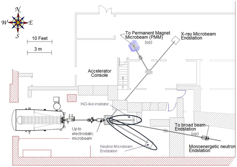
The RARAF Accelerator hall. The two new beam lines (0° for the IND-like neutron irradiator and 30° South for the neutron microbeam) are circled.
2. Broad energy neutron small animal irradiator
In the past, RARAF has provided neutron irradiations with mono-energetic neutrons having energies from 0.22 to 15 MeV for a wide variety of applications ranging from cellular studies [3–5], mice [6, 7], microelectronics devices and even for calibrating detectors for Weakly Interacting Massive Particles (WIMPs) [8]. Currently we are in the process of assembling a novel neutron target system to provide a broad-range energy spectrum from 100 keV to 10 MeV that will approximate the Hiroshima atomic bomb neutron spectrum [9]. This novel neutron source has been motivated by the increased interest in the study of realistic irradiation scenarios in radiation biology in general and in the field of biodosimetry in particular.
Up to now most biodosimetry work has been performed using uniform exposures of gamma rays, which is not a realistic model for many of the scenarios of interest [10]. These scenarios may involve a significant component of dose from energetic neutrons. Neutrons are known to be much more efficient than gamma rays at inducing acute radiation syndrome, both for gastrointestinal and for hematopoietic death [11].
In particular, National Planning Scenario #1 [10] describes a 10 kT improvised nuclear device (IND), detonated in downtown Washington DC. This is an enriched uranium gun-type device very similar to the 15 kT “Little Boy” detonated over Hiroshima. Our goal, therefore, is to mimic the neutron spectra from such a device at relevant distances from the epicenter. As our benchmark spectrum we have taken the Hiroshima neutron spectrum at 1.5km [9]. This spectrum is significantly different from a standard reactor fission spectrum, because the spectrum is moderated as the neutrons are transported through air over long distances, and is dominated by neutron energies between 0.05 and 8 MeV (see figure 2).
Figure 2.
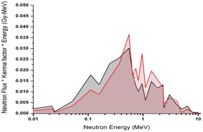
MCNPX simulated neutron dose (red hashed curve, corresponding to a 2:1 deuteron / proton mix on a thick beryllium target, behind a water moderator, as compared to [9] – calculated at 1.5 km from the epicenter at Hiroshima. Data plotted is the dose weighted neutron flux.
2.1 Method
To generate a broad energy range neutron beam with our accelerator, we propose to use a mixed beam of deuterons, protons and molecular ions (H2+/D2+), accelerated to 5 MeV impinging on a thick (1 mm) beryllium target. The resultant neutron spectrum is the sum of the spectra from the 9Be(d,n) reaction (which generates higher energy neutrons) and the 9Be(p,n) reactions (which generate lower energy neutrons).
The shape of the resulting spectrum can be adjusted by using an appropriate mixture of hydrogen and deuterium in the ion source, and by sampling the neutrons from the target at an appropriate angle.
The predicted accelerator-based neutron spectra have been evaluated using the MCNPX Monte Carlo code [12], and compared with the IND-like spectrum from [9]. To validate the simulation results, MCNPX calculations for a 7.44 MeV deuteron beam incident on a thick aluminum target were compared to measurements made at a back emission angle. The results of the Monte Carlo simulation and the measured spectrum are renormalized and the scale factors are used for the 5 MeV deuteron beam comparison. The following simulations indicate that the closest match is obtained (see Figure 2) using a ratio of protons to deuterons of 2. The calculated accelerator-based neutron spectrum (shown as hatched red in the Figure) compares well with the computed Hiroshima spectrum (shaded grey). The calculated dose rate for 200 μA total beam current is 4.4 Gy/hr at 10 cm away from the target and 60° with respect to the original deuteron direction..
In order to validate these calculations we have used Ohio University's Edwards Accelerator Laboratory to measure neutron angular distribution and spectrum from the 9Be(d,n) reaction (Figure 3) and are in the process of measuring the 9Be(p,n) yields.
Figure 3.
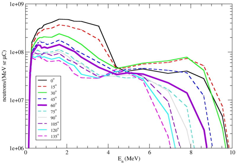
Neutron yields from a 5 MeV deuteron beam on a thick beryllium target. The 60° spectrum is highlighted.
For these measurements a mixed array of two 8-mm lithium glass detectors (96% 6Li) and one NE213 detector was used. The detector efficiency was calibrated against the Al(d,n) standard at 7.44 MeV and 120°. The beryllium target was placed in a low-mass scattering sample holder. Good charge collection and electron suppression were assured by use of a 300 V potential in the target holder. The measurements were made at 15° spacing between 0° and 135°.
As seen in figure 4, the high energy neutron yields from the 9Be(d,n) neutron reaction at 60°, match the high energy part of the Hiroshima neutron spectrum rather well. In the intermediate energy range, the deuteron-induced spectrum underestimates the required one significantly. This can be corrected by adding neutrons from the 9Be(p,n) reaction which produce a significant neutron component up to about 2 MeV [13].
Figure 4.
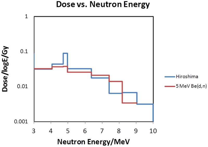
Comparison of the high energy component of the neutron spectrum from [9] with that from a 5 MeV deuteron beam impinging on a thick beryllium target, sampled at 60°.
2.2 Endstation design
The beryllium target (Figure 5a) was manufactured by Materion Brush Corp. (Elmore, OH). The target is a 99.0% pure 1 mm thick beryllium window, diffusion bonded to a single-sided 2¾ inch Conflat flange over a 39 mm aperture. It is guaranteed bakeable to 450°C. In order to overcome the expected heat load on the target of 1 kW (5 MeV × 200 μA over a 2 cm diameter), we have designed a target cooling system based on a submerged jet, as shown in figure 4b. The downstream side of the target serves as one wall in a water filled chamber; a water jet is injected into this chamber and impinges on the target. This is a much more efficient cooling mechanism than the more conventional water flow across the target. Simulations using ANSYS multiphysics (Ansys Inc Canonsburg, PA) have demonstrated that a 5 m/sec water jet will cool the target sufficiently. We have also simulated the pressure on the back of target. With the nozzle about 1 cm away from target, there will be about 10 kPa of additional pressure on the target, which is much lower than the Cu yield strength.
Figure 5.
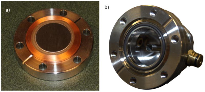
a) Beryllium target bonded to a Conflat flange. b) Photo of the cooling chamber.
The target cooling will be initially tested by applying a heater to the beam side of the target and measuring the temperature change on the back side of the target under various water flows. If necessary the back of the target can be scored to increase the efficiency of heat transfer at the stagnation point [14].
For irradiations, mice will be placed in plastic tubes and hung on rods mounted on the face of a “Ferris wheel” rotator. The tubes are free to rotate around the rods as the wheel rotates around the charged particle beam axis. In this manner, variations in dose rate around the target structure are averaged and the mice will be irradiated essentially uniformly from all directions. The direction of the mouse tubes will be reversed at mid-dose to average dose variations due to the differences in angle and distance between the positions of the ends of the tubes. The rotator will be placed such that the centers of the mice are at an angle of 60° to the axis of the beam and at a distance of 10 cm from the target.
2.3 Shielding
The RARAF accelerator hall was originally shielded against radiation formed incidentally on the various apertures in the various beam lines but until now we were not generating significant neutron yields in this area. With the development of a new, intense neutron source, placed adjacent to the target area exit maze, we have performed a detailed study of the existing shielding at our facility. Using the construction diagrams we have identified the shape and dimension of each of the concrete blocks surrounding the T0 endstation. We have then performed an MCNPX calculation to determine expected dose rates at various locations around our facility.
Following these studies we have decided to reinforce the shielding in the entrance maze to the irradiation hall. We will add a 5” thick polyethylene door as well as polyethylene ceiling panels above the endstation.
Once beam is available, we will conduct a full survey using an ionization survey meter to measure the total dose and a moderated BF3 survey instrument to measure the neutron dose equivalent to verify that no hotspots exist.
2.4 Beam Diagnostics
Total dose will be measured in a mouse phantom using a small tissue-equivalent ionization chamber filled with methane tissue-equivalent gas. The gamma-ray component of the dose will be measured using a compensated Geiger-Müller detector and/or an aluminum ionization chamber filled with argon. Measurements will be made relative to the charged particle beam current and to a monitor ionization chamber. The neutron spectrum will be measured using a combination of a gas filled spherical proportional counter (for the low energy components) and a liquid scintillation counter (for the high energy component).
3. The neutron microbeam
A single-cell microbeam [15] is a very narrow beam of radiation of micrometer dimensions. Together with integrated techniques for imaging cellular, or other small-volume targets, microbeams allow precisely defined quantities of damage to be induced at precisely defined locations. Thus the microbeam is essentially a tool for investigators to study intra- and inter-cellular mechanisms of damage signal transduction. It can also be applied to detect the equivalent events in microelectronic devices.
Following our development of microbeams for charged particles [2] and x rays [16], our users have been requesting a neutron microbeam – the only ionizing radiation for which microbeam technology has not to date been applied. The interest in neutrons is both mechanistic and also practical, relating to the biological effects of intermediate-energy neutron exposure in the nuclear power industry.
3.1 Method
The 7Li(p,n)7Be nuclear reaction, which has a threshold at 1.881 MeV, is a well-known source for generating neutrons. The near-threshold reaction provides a relatively high neutron yield, as well as a very narrow forwardly-peaked angular distribution for the outgoing neutrons [17] (figure 6a). The narrow forward-peaked neutron microbeam results from the fact that the velocity of the center of mass is greater than the relative outgoing velocity of the neutrons. As we show, this “kinematic collimation” enables us to produce neutron microbeams of diameter 8 to 20 μm (depending on the energy above threshold), starting with a proton microbeam with a diameter of 5μm [1]. Neutron scattering in the thin gold target is negligible.
Figure 6.
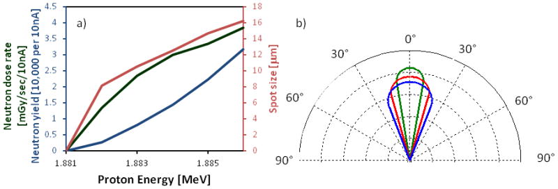
a) Normalized angular distribution of neutrons for 1.882 MeV (green), 1.884 MeV (Red) and 1.886 MeV (blue). b) Neutron yield (expressed as actual yield in blue and dose rate in green) and neutron spot size (red) as a function of initial proton energy, assuming a 10nA proton beam and a 5μm proton spot size.
Using a proton beam current of 10nA, neutron fluxes of dose rates of 0.08–0.23 Gy/min are achievable (figure 6b).
Compared to the “standard” charged particle microbeam [2], where small spot size is paramount and beam flux of secondary importance, the neutron microbeam requires a high proton beam current to achieve biologically relevant neutron yields. We have therefore redesigned the electrostatic focusing system to have a higher acceptance by increasing the limiting aperture [2] and modifying the support structures within the lens assembly (shown in figure 7a) to remove all collimation.
Figure 7.
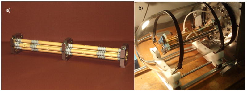
a) Photo of electrostatic quadruplet. b) Quadruplet in bell jar test chamber. The test chamber is equipped with individual feedthroughs for all 16 electrodes as well as a turbo pump and residual gas analyzer.
The focusing system is based on the original RARAF electrostatic lens [15, 18]. This is an electrostatic quadrupole quadruplet (see figure 6). The electrodes are gold plated onto ground Macor (machineable glass-ceramic, Corning Inc.) rods. Alignment of electrodes relative to each other is “guaranteed” by their one-piece, high-precision construction.
In terms of electrostatic design, we have adopted “Russian symmetry” which insures a circular beam spot. Specifically, the lens strengths are (+A, −B, +B, −A). The pole lengths were selected such that the operating voltage on each electrode would be roughly equal – to ensure no “weak links”. Indeed, tests of the lens in our bell-jar test system revealed no discharges or corona up to 10kV.
The proton beam entering the lens is defined by a 100 μm diameter object aperture 3.5 m upstream from the lens. A second, 100 μm, limiting aperture at the entrance to the first lens element eliminates protons that would have high spherical aberrations in the lens. The effective focal length of the lens is 22 cm, resulting in a demagnification of 22, This results in a beam spot at the focal point of about 5 um.
At the endstation, the quadruplet lens is mounted on a 2D pivot adjustment plate, and can rotate around its center plane. By adjusting the pivot plate tilt angle, the lens is aligned with the beam. The whole lens holder system is mounted on rails on the beam end station table.
3.2 Endstation design
The experiment station design is based closely on our standard microbeam endstation configuration [19, 20] with the main difference being that all other endstations were designed for a vertical beam and this one was designed for a horizontal beam. In addition to the lens assembly, the endstation consists of:
A sample holder, mounted on an XYZ stage with 0.1μm step size (Thorlabs, Newton, NJ).
A solid state semiconductor detector to detect the protons and measure their energies during beam diagnostics.
A fluorescence imaging system which includes a fast Camlink CMOS camera (PhotonFocus AG, Lachen, Switzerland) and a lens tube with both low magnification (4×) and high magnification (20×) microscope objectives (Morell Instruments, Melville NY). The image frame grabber is a Matrox Helios card. The image processing code was written using the MIL 9.0 library (Matrox Imaging, Dorval, Quebec, Canada).
-
The entire setup is on an isolation table and covered by an enclosure to block light and maintain temperature/humidity for the cells..
Initially for beam diagnostic purposes, the focused proton beam will be operated at low flux, by adding a collimator at the entrance to the electrostatic lens. The proton beam will exit the vacuum system through a thin silicon nitride exit window and we will determine the lens settings for optimal proton spot size and location using our standard knife edge and bead scan techniques [2, 19]. This will also be the center of the neutron microbeam. Once lens settings have been found, the collimator will be removed and the silicon nitride microbeam window will be replaced by a neutron target consisting of a 20 μm thick gold foil with a thin LiF layer on the vacuum side. The neutron beam size will be measured using a fluorescent nuclear track detector (FNTD) chip using a confocal laser scanning microscope [1]. The neutron dose rate will be measured using a microdosimeter prior to each set of irradiations and monitored using beam current.
For irradiations, the cells are imaged by a horizontal imaging system. The irradiation protocol for initial cell irradiations will be the same as for the other microbeams: scan the dish for cells at low magnification, then zoom in and image at higher magnification only those areas which contain cells, move the cells to the beam location, and irradiate.
An alternative, flow-through system using microfluidics is also under development.
3.3 Initial tests
A proof-of-principle test was conducted using a collimator system. The proton beam was collimated by a copper disc with a 1 mm diameter aperture. The target system included a target holder with 1 mm diameter hole, a thin LiF foil target on a 40 um Au/Al foil back plate. The initial proton beam was stopped at the back plate but the neutron beam, with more penetrability, passed through. The beam size measurement was made using a very thin layer of lithium carbonate, enriched in 6Li, and an FNTD chip obtained from Mark Akselrod of Landauer Inc. In the lithium carbonate, the neutrons generate alpha particles through the 6Li(n,α) reaction. At the back of the lithium carbonate the alpha particles left tracks on the surface of the FNTD. Using a confocal laser scanning microscope, the alpha tracks were counted and the profile of beam is shown in figure 8. Based on the geometry of this system, the 2 mm diameter of the beam size is consistent with what was predicted.
Figure 8.
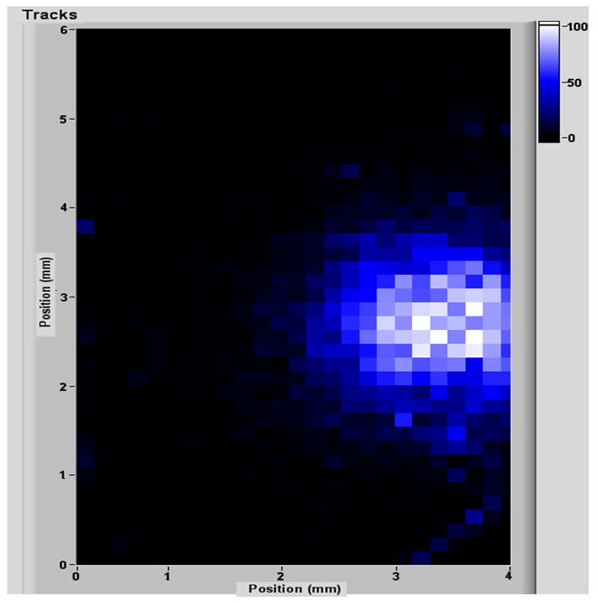
Image of a 2mm neutron beam on an FNTD.
Acknowledgments
Development of the IND-like broad energy neutron source is supported by grant number U19 AI067773 to the Center for High-Throughput Minimally Invasive Radiation Biodosimetry from the National Institute of Allergy and Infectious Diseases / National Institutes of Health.
Development of the Neutron microbeam is supported by grant number P41 EB002033 to the Radiological research Accelerator Facility from the National Institute of Biomedical Imaging and Bioengineering/ National Institutes of Health.
The Be(d,n) cross section measurements were supported by U.S. DOE grant number DE-FG52-09NA29455/A000.
This is an author-created, un-copyedited version of an article accepted for publication in Journal of Instrumentation. IOP Publishing Ltd is not responsible for any errors or omissions in this version of the manuscript or any version derived from it. The definitive publisher-authenticated version is available online at http://dx.doi.org/10.1088/1748-0221/7/03/C03031.
References
- 1.Xu Y, et al. An accelerator-based neutron microbeam system for studies of radiation effects. Radiation Protection Dosimetry. 2011;145(4):373–376. doi: 10.1093/rpd/ncq424. [DOI] [PMC free article] [PubMed] [Google Scholar]
- 2.Randers-Pehrson G, et al. The Columbia University sub-micron charged particle beam. Nuclear Instruments and Methods in Physics Research Section A: Accelerators, Spectrometers, Detectors and Associated Equipment. 2009;609(2–3):294–299. doi: 10.1016/j.nima.2009.08.041. [DOI] [PMC free article] [PubMed] [Google Scholar]
- 3.Borek C, Hall EJ, Rossi HH. Malignant transformation in cultured hamster embryo cells produced by X-rays, 460-keV monoenergetic neutrons, and heavy ions. Cancer Res. 1978;38(9):2997–3005. [PubMed] [Google Scholar]
- 4.Freyer GA, et al. Neoplastic transformation of mouse C3H10T1/2 cells following exposure to neutrons does not involve mutation of ras gene as analyzed by SSCP and cycle sequencing. Mutat Res. 1996;357(1–2):237–44. doi: 10.1016/0027-5107(96)00130-3. [DOI] [PubMed] [Google Scholar]
- 5.Miller RC, et al. Oncogenic transformation in C3H10T1/2 cells by low-energy neutrons. Int J Radiat Biol. 2000;76(3):327–33. doi: 10.1080/095530000138664. [DOI] [PubMed] [Google Scholar]
- 6.Carsten AL, V, Bond P, Thompson K. The r.b.e. of different energy neutrons as measured by the heamatopoietic spleen-colony technique. Int J Radiat Biol Relat Stud Phys Chem Med. 1976;29(1):65–70. doi: 10.1080/09553007614551561. [DOI] [PubMed] [Google Scholar]
- 7.Worgul BV, et al. Quantitative assessment of the cataractogenic potential of very low doses of neutrons. Radiat Res. 1996;145(3):343–9. [PubMed] [Google Scholar]
- 8.Aprile E, et al. New measurement of the relative scintillation efficiency of xenon nuclear recoils below 10 keV. Physical Review C. 2009;79(4):045807. [Google Scholar]
- 9.Egbert SD, Kerr GD, Cullings HM. DS02 fluence spectra for neutrons and gamma rays at Hiroshima and Nagasaki with fluence-to-kerma coefficients and transmission factors for sample measurements. Radiat Environ Biophys. 2007;46(4):311–25. doi: 10.1007/s00411-007-0120-5. [DOI] [PubMed] [Google Scholar]
- 10.Homeland_Security_Council. National Planning Scenarios (Final Version 21.3) Washington DC: 2006. [Google Scholar]
- 11.Jones TD, et al. Neutron RBEs for cytopenia and repopulation of stroma and hematopoietic stem cells: Mathematical models of marrow cell kinetics. Health Physics. 1997;72(4):530–543. doi: 10.1097/00004032-199704000-00004. [DOI] [PubMed] [Google Scholar]
- 12.Hendricks JS, et al. MCNPX, Version 2.5.c. 2003, Los Alamos National Laboratory Report LA-UR-03–2202. Los Alamos, NM: [Google Scholar]
- 13.Howard WB, et al. Measurement of the [sup 9]Be(p,n) thick target spectrum for use in accelerator-based Boron Neutron Capture Therapy. Medical Physics. 1996;23(7):1233–1235. doi: 10.1118/1.597684. [DOI] [PubMed] [Google Scholar]
- 14.Gabour LA, Lienhard JHV. Wall Roughness Effects on Stagnation-Point Heat Transfer Beneath an Impinging Liquid Jet. Journal of Heat Transfer. 1994;116(1):81–87. [Google Scholar]
- 15.Bigelow AW, et al. Single-Particle/Single-Cell Ion Microbeams as Probes of Biological Mechanisms. Plasma Science, IEEE Transactions on. 2008;36(4):1424–1431. [Google Scholar]
- 16.Harken AD, et al. The Columbia University proton-induced soft X-ray microbeam. Nuclear Instruments & Methods in Physics Research Section B-Beam Interactions with Materials and Atoms. 2011;269(18):1992–1996. doi: 10.1016/j.nimb.2011.05.033. [DOI] [PMC free article] [PubMed] [Google Scholar]
- 17.Lee CL, Zhou XL. Thick target neutron yields for the Li-7(p,n)Be-7 reaction near threshold. Nuclear Instruments & Methods in Physics Research Section B-Beam Interactions with Materials and Atoms. 1999;152(1):1–11. [Google Scholar]
- 18.Dymnikov AD, et al. Theoretical study of short electrostatic lens for the Columbia ion microprobe. Review of Scientific Instruments. 2000;71(4):1646–1650. [Google Scholar]
- 19.Bigelow AW, et al. The Columbia University microbeam II endstation for cell imaging and irradiation. Nuclear Instruments & Methods in Physics Research Section B-Beam Interactions with Materials and Atoms. 2005;231:202–206. [Google Scholar]
- 20.Randers-Pehrson G, et al. The Columbia University single-ion microbeam. Radiation Research. 2001;156(2):210–214. doi: 10.1667/0033-7587(2001)156[0210:tcusim]2.0.co;2. [DOI] [PubMed] [Google Scholar]