

Abstract
Nanofluidic sensing elements have been the focus of recent experiments for numerous applications from nucleic acid fragment sizing to single-molecule DNA sequencing. These applications critically rely on high measurement fidelity, and methods to increase resolution are required. Herein, we describe fabrication and testing of a nanochannel device that enhances measurement resolution by performing multiple measurements (>100) on single DNA molecules. The enhanced measurement resolution enabled length discrimination between a mixture of λ-DNA (48.5 kbp) and T7 DNA (39.9 kbp) molecules, which were detected as transient current changes during translocation of the molecules through the nanochannel. As long DNA molecules are difficult to resolve quickly and with high fidelity with conventional electrophoresis, this approach may yield potentially portable, direct electrical sizing of DNA fragments with high sensitivity and resolution.
Keywords: Nanofluidic, DNA, Single-Molecule, Sizing, Nanopore, Electrophoresis
Introduction
The study of single biomolecules such as nucleic acids and proteins has provided the ability to learn new insights that were previously masked by ensemble measurements1. Tools such as nanopore sensors have attracted attention for the study of single biomolecules as they provide direct electrical signals indicative of the structure of a molecule as it passes through the nanopore2–6. These nanopores are typically either biological, such as α-hemolysin inserted into a lipid membrane, or inorganic nanometer-scale holes in thin dielectric membranes. The nanopore separates two reservoirs filled with an electrolyte solution, and upon application of a voltage bias across the membrane, an ionic current is driven through the pore. Translocation of single molecules such as DNA through the pore results in a measurable transient current signal7, 8. The translocation signal depends on various factors including the electrokinetic driving force, molecule-pore interactions, and length of the molecule9. A number of novel applications have been investigated using nanopore sensors including DNA sequencing10, label-free detection of single nucleotide polymorphisms11 and mapping of DNA-binding proteins12.
The ability to accurately measure nucleic acid length and differentiate nucleic acid fragments with different lengths has important implications for diverse applications such as profiling of short tandem repeat (STR) markers13, biomedical diagnostics14, and biodefense15. While fluorescence-based methods for length measurements have achieved high measurement resolution (~5%)16, 17, the need for sources, optics and detectors limit their portability, particularly for on-field applications. Moreover, the scalability of resolution using optical systems to short DNA fragments is typically restricted by diffraction-limited optics. Electrophoresis-based methods18 also provide high resolution; however, long DNA molecules require specialized methods for separation and there are limitations on the analysis time and sample size. Nanopore sensors offer the potential for rapid, label-free sizing and mapping of DNA at the single molecule level with a direct electrical readout, which may be advantageous over other methods based on fluorescence or electrophoresis. Potentially, nanopores also offer a platform that is easily integrated with microfluidic devices. However, the resolution of nanopores to size or map DNA molecules is currently limited by variability in DNA translocation time and conformations, as well as the limited signal-to-noise ratio arising from insufficient measurement time during translocation19, 20. Integrating the area of the current blockade over time (electron charge deficit) has been shown to account for different folded conformations of the translocating DNA molecule19, 21, but till date it has not been possible for nanopore sensors to differentiate DNA molecules with lengths differing by less than 30%. A promising approach to overcome this issue is to repeatedly measure the transient current signal of the same molecule, which can result in improved resolution through statistical averaging22. Gershow et al23 first showed recapture of 4–10 kbp DNA molecules in solid-state nanopores by reversing the applied voltage bias after detection of a translocation event. The recapture process was shown to depend on the competition between diffusion and electrophoresis outside of the nanopore, but the recapture probability was less than 70%. Hence, while multiple measurements were demonstrated, the low recapture efficiency precluded large numbers of measurements to be reliably performed on each molecule, and the ability of multiple measurements to improve resolution of the nanopore was not shown.
Herein, we report facile fabrication and testing of a nanofluidic device to interrogate single DNA molecules multiple times as transient changes in ionic current through a nanochannel (Figure 1). The devices were engineered to provide sufficient electric field around the nanochannel for a high recapture probability (>99%) and enabled large numbers of consecutive measurements (>100) to be performed on single molecules. Consequently, we provide the first experimental validation that statistical averaging of the translocation current amplitude over multiple measurements increases the measurement resolution, and quantify the resolution enhancement as a function of the number of measurements. We use this resolution enhancement from multiple measurements to discriminate between a heterogeneous mixture of DNA molecules with different lengths (48.5 kbp λ-DNA and 39.9 kbp T7-DNA molecules), which was not possible using one measurement per molecule. These nanofluidic devices have the advantages of a simple fabrication strategy (micromolding) and ease of integration with microfluidics upstream of the nanochannel.
Figure 1.
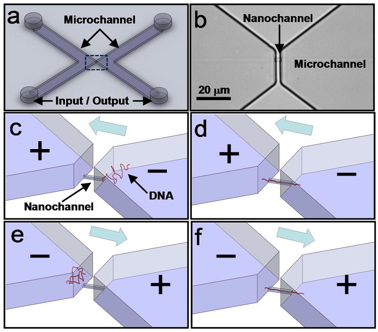
Nanofluidic device. a) Schematic of device showing inlet and outlet reservoirs and microchannels. b) Micrograph of the device (dotted area in (a)) showing a 200 nm × 500 nm × 4 μm nanochannel that connects the two microchannels. c, d) Application of a voltage bias across the nanochannel drives the DNA into the nanochannel. e, f) Upon completion of the translocation, the voltage bias is reversed to translocate the same molecule in the reverse direction. This process is repeated to obtain multiple translocations of the same DNA molecule through the nanochannel.
Materials and methods
Device fabrication
Nanochannel devices were fabricated by micromolding in polydimethylsiloxane (PDMS). 200 nm thick, 500 nm wide titanium (Ti) metal lines were patterned using e-beam lithography lift-off technique to define the nanochannel. A thick layer of photoresist (10 μm, SU-8) was patterned on top of the Ti features to define the connecting microchannels. The length of the nanochannels was 4 μm. PDMS was cast on the mold, cured and peeled off, followed by bonding to a glass slide using oxygen plasma. The device comprised two microfluidic channels with a single nanochannel serving as the only electrical and fluidic connection between the two microchannels. The microchannel and nanochannel dimensions were 0.8 cm × 1 mm × 10 μm, and 4 μm × 500 nm × 200 nm (length × width × height), respectively.
To prevent adhesion of the DNA molecules to the surface of the nanochannel, the nanochannel surface was first passivated with bovine serum albumin (BSA, Sigma Aldrich). 1 mg/mL of BSA was dissolved in 1/15 × (diluted from 1×) phosphate buffered saline (PBS, conductivity of σ = 0.1441 S/m, pH 7.4, composition given in the supporting information) and flowed into the device for 10 min before introduction of DNA. DNA samples (48.5 kbp λ-DNA, New England Biolabs and 39.9 kbp Bacteriophage T7 DNA, Boca Scientific) were dissolved in 1/15 × PBS to a final concentration of 1 μg/mL of λ-DNA, or a mixture of 1 μg/mL of λ-DNA and 1 μg/mL of T7 DNA. The DNA solution was then injected on one side of the nanochannel, while the other side was injected with only 1/15 X PBS solution.
Ag/AgCl electrodes (In Vivo Metric, Healdsburg, CA) were inserted into the microchannel reservoirs on opposite sides of the nanochannel for making electrical contact with the solution. A patch clamp amplifier (Axopatch 200B, Molecular Devices) was used to apply a voltage bias, record the corresponding ionic current through the nanochannel, and filter the data (80 dB/dec) at 1 kHz cutoff frequency. Current measurements were obtained inside a custom-built Faraday cage to shield the devices from any electromagnetic interference, and the measured current data were digitized and recorded using Digidata 1440A and associated software (Molecular Devices). To perform feedback control and multiple measurements on single molecules, current data was digitized at 20 kHz/16 bits using a Data Acquisition Card (DAQ) (PCI-6251M, National Instruments) controlled by LabVIEW (National Instruments). A shielded connector card (SCB-68) was used to send a voltage signal to the Axopatch amplifier to control the driving voltage (±1 V) applied by the Axopatch amplifier. Translocation signals at a driving voltage of ±1 V (the maximum voltage that can be applied by the Axopatch 200B amplifier) yielded sufficiently large translocation amplitudes and durations (20–50 pA, 4 ms) for automated real-time detection with LabVIEW.
Real-time feedback control algorithm
A feedback control algorithm for performing multiple measurements on single DNA molecules was implemented in LabVIEW. To detect a DNA translocation event, the last 1 ms interval of digitized ionic current data was averaged and considered as real-time current ia, while the 3 ms interval of digitized ionic current prior to the last 1 ms was averaged and considered as open nanochannel current ib. Since the entry of a DNA molecule into the nanochannel caused an increase of ionic current of ~40 pA for λ-DNA, and ~30 pA for T7 DNA, the algorithm identified a translocation event when ia exceeded ib by a threshold of 10 pA (i.e. ΔI > 10 pA). (2) Upon detection of a DNA molecule in the nanochannel, the polarity of the voltage bias was reversed after a delay of 30 – 40 ms to allow for completion of translocation (duration was 4±2 ms) while avoiding immediate recapture after voltage reversal when the current was rapidly changing. The loop continued, resulting in multiple translocations of the same molecule through the nanochannel.
Data analysis
Translocations were identified and analyzed offline using a second algorithm. To identify a DNA translocation event, a time scale, t0, was chosen such that it was small enough that the changing baseline current after voltage reversal could be approximated with a linear regression, but long enough that the translocation signal could not be well approximated. Linear regressions of duration t0 were fit to the current vs. time trace. During the translocation, the linear fit failed to follow the current accurately, thereby increasing the error in the regression (residuals) and allowing for the identification of the translocation. For each segment (current trace between two consecutive voltage reversals), the maximum, initial (first segment right after voltage reversal), and mean residuals (errors) in the linear regression for each segment were computed. A DNA translocation event was defined when the maximum residual in any segment exceeded a threshold value. To accurately determine the amplitude of each translocation, the capacitive transient following voltage reversal was fit and subtracted from the data. Since the translocation waveform had a maximum transient current peak as well as a slight minimum preceding it, the difference between the maximum and minimum current in the vicinity of the translocation was calculated and defined as the translocation amplitude.
Results and discussion
Figure 1a,b depicts the nanofluidic devices comprising a single nanochannel (200 nm × 500 nm × 4 μm ) connecting two microchannels (0.8 cm × 1 mm × 10 μm) on either side. At 1 V voltage bias with low buffer salt concentrations (1/15 X PBS), the devices were capable of detecting single molecules of λ-DNA (48.5 kbp) and T-7 DNA (39.9 kbp) from the transient increase in ionic current through the channel (ΔI). The transient current increase is due to the introduction of mobile counter-ions screening the inherent charge on the DNA molecules into the nanochannel7, 8. For Δn counterions of mobility μ introduced into a channel of length L, with fraction b of counterions that are mobile, electron charge e, and voltage bias V, the change in ionic current is approximately given by24
| (1) |
Assuming that the entire DNA molecule is enclosed in the nanochannel, we expect a current increase of 15.6 pA for λ-DNA and 12.6 pA for T7 DNA (μ = 5.4×10⁻⁸ m2/Vs for Na+, b = 0.3 for ~10 mM NaCl salt concentration25, 26), which is consistent with the observed translocation current increase of 20–30 pA. At relevant salt concentrations and surface treatments, the electroosmotic mobility of the BSA-coated surfaces can be estimated μEOF = 2 × 10⁻⁸ m2/V s 27,28. The experimentally measured effective DNA translocation duration of ~ 4 ms given by L/(μEP – μEOF)E corresponds to an electrophoretic mobility of roughly μEP = 2.4 × 10⁻⁸ m2/V s, which is consistent with the free-solution mobility of DNA in the presence of Na+ as measured by Ross et. al29. Thus, while the DNA molecules moved from the negative to positive electrode, the electroosmotic flow significantly decreased their velocity.
Multiple measurements on single DNA molecules
The real-time feedback control algorithm was designed to reverse the applied voltage bias after each DNA translocation, thereby performing multiple measurements on the same DNA molecule (Figure 1c-f). A typical current trace pattern for a solution containing a mixture of 1 μg/mL λ-DNA and 1 μg/mL T7 DNA (Figure 2) reveals successive events comprising a DNA translocation followed by a voltage reversal. After voltage reversal, the current changes sign and starts decreasing rapidly to its baseline value. Upon detection of a DNA translocation event, the voltage bias is again reversed after a delay of 30–40 ms (Figure 2a). The translocation events occur alternately at forward and reverse voltage bias, as expected when the DNA molecule is recaptured back into the nanochannel and translocated alternately in forward and reverse directions (Figure 1c-f). Viewed over a longer period of time (Figure 2c), the current trace reveals that the translocation events are grouped into distinct sets separated by pauses. The pauses between neighboring sets in Figure 2c indicate that a translocation event was not detected either following escape of the molecule being recaptured or failure of the algorithm to detect the translocation. Upon detection of another translocation event, the pause terminates and another set of successive measurements begins. The regular translocation events in each set interrupted by much longer pauses suggest that each set corresponds to a single DNA molecule being actively shuttled back and forth through the nanochannel.
Figure 2.

Current traces with feedback control for a mixture of 1 μg/mL λ-DNA and 1 μg/mL T7 DNA. a) Translocation signal of a single DNA molecule (red arrow). Delay time before voltage reversal is also indicated. b) Current traces showing multiple measurements presumably on the same DNA molecule. When each translocation event (red arrow) is detected, the applied voltage bias is reversed, resulting in successive recapture and translocation of the same molecule. c) Current traces over a longer period show sets of translocation events separated by pauses that occur whenever the DNA molecule escapes or the translocation is not identified by the real-time algorithm. Vertical lines in the plot correspond to transient current changes that occur when the applied voltage bias is reversed, with each vertical line indicating a voltage reversal following detection of a translocation event.
Identification of DNA translocation events
Identifying translocations required a method for accurately detecting peaks in ionic current during the decaying current transient that followed voltage reversal (Figure 2a). For a mixture of 1 μg/mL λ-DNA and 1 μg/mL T7 DNA, Figure 3a depicts the maximum, initial, and mean linear regression residuals in each segment of current trace between two voltage reversals, with each linear fit spanning a time interval t0 = 1.5 ms. The residual from the linear regression for the first segment right after voltage reversal, called initial residual, was typically higher than the mean residual. However, the maximum residuals from the linear regressions were clearly distinguished from the initial and mean residuals (Figure 3b), and corresponded to the DNA translocations. Hence, DNA translocation events were identified based on a threshold residual that cleanly separated residuals corresponding to DNA translocations from the initial and mean residuals. It was manually verified that initial residuals above the threshold were caused by a translocation event very soon after voltage reversal. Each segment with a maximum residual below the threshold value was manually checked to ensure that it did not contain a translocation (which would correspond to a missed translocation). With this criterion, the data analysis missed less than 1 in 10,000 translocations, and did not incorrectly identify any baseline current transients as translocation events. Identification of DNA translocation events enabled extraction of translocation signal amplitudes and analysis of the current traces.
Figure 3.

a) Visual representation of translocation identification algorithm showing raw data measured by Axopatch 200B (blue) and consecutive linear regressions fit to the data (red). b) Maximum (red), initial (green) and mean (blue) residuals of consecutive segments of current traces between two voltage reversals. The solid line depicts the threshold residual for determining whether a translocation event occurred in the segment.
Recapture Time Distribution: Simulation and Experiment
The recapture of a DNA molecule by a nanopore or nanochannel depends on the competition between diffusive and electrokinetic transport. This process can be characterized by a recapture radius such that a molecule within this distance from the pore can be recaptured into the pore with a high probability. This recapture radius scales proportionally with the current through the pore, and inversely with the solution conductivity and molecular diffusivity23. In the present device, the large cross section area of the nanochannel, large applied voltage (1 V), and the low diffusivity of the λ-DNA and T7 DNA molecules, all favor a larger recapture radius compared to the case of a nanopore in a membrane23. Assuming spherical symmetry, the calculated recapture radius for λ-DNA in the device is 88 μm (see supporting information), which exceeds the microchannel height of 10 μm. Thus, beyond a distance of ~10 μm, the microchannel further confines the electric field.
To investigate the mechanism of DNA recapture and the role of the microchannels, we compared the molecule recapture time distribution with numerical simulations. The recapture time is defined here as the time between voltage reversal and translocation of the molecule. Prior to recapture, transport of DNA molecules around the nanochannel is influenced by diffusion, electrophoresis, and electro-osmosis. Since the cross-sectional area of nanochannel is more than an order of magnitude smaller than that of the adjacent microchannel, the DNA transport in this region can be approximated as spherically symmetric for length scales smaller than the microchannel height. Simulation of DNA transport is obtained by solving the one-dimensional time-dependent drift-diffusion equation in spherical coordinates23:
| (2) |
Where DNA diffusivity D = 4×10⁻¹³ (m2/s), r is the distance away from the nanochannel, c is the concentration (in this case the probability density) of DNA molecule, and μ= 4×10⁻⁹ (m2/V s) is the measured DNA mobility. The electric field in the microchannels was obtained by solving Gauss’ equation for the device geometry and applied voltage.
The initial condition for the probability distribution, c, was set as a delta function located close to the nanochannel entrance. The probability distribution was allowed to propagate under an electric field for 32.5 ms, which corresponds to the period before the applied voltage is reversed, during which the DNA molecule continues to move away from the nanochannel. The direction of the electric field was then reversed to drive the probability distribution towards the nanochannel. The recapture time distribution was calculated by computing the difference in the probability distribution outside the nanochannel between time steps.
Figure 4 compares the simulated recapture time distribution for a pre-reversal time of 32.5 ms to the experimentally measured recapture time distribution for pre-reversal times in the range of 30–35 ms. The experimental results agree with the simulation result, where most of the molecules were recaptured within 100 ms, and both experimental and simulation peaks of the recapture time were centered around 40~50 ms. The small discrepancies at the right end of the distribution may be attributed to effects of surface charge30, interaction between DNA molecules and channel walls, the effect of electric field strength on DNA conformation, and the finite DNA size, which were not included in the simulation.
Figure 4.

Experimental histogram and simulation for DNA recapture time distribution (The time between voltage reversal and molecule arrival).
The simulated mean DNA travel distance during the pre-reversal time (1.38 μm) and the characteristic diffusion length scale during recapture (0.3 μm) were both significantly smaller than the microchannel height (10 μm) and the recapture radius (88 μm, supporting information). These results suggest that the primary mechanism for the high recapture probability in the device was the larger recapture radius due to a combination of the larger nanochannel size, higher applied voltage, and lower DNA diffusivity. The results also indicate that the electric field confinement due to the microchannels did not directly aid in DNA recapture.
Enhanced discrimination of DNA molecules
To enable statistical averaging over multiple measurements on single molecules, it is important to identify sets of translocation events that correspond to back-and-forth translocations of the same molecule. A series of measurements on the same molecule was defined as a set of translocation events with a) exactly one voltage reversal between successive translocations, and b) <500 ms delay between neighboring translocation events (compared to a mean arrival time of ~10 s under a constant voltage bias and a mean recapture time of 30 ms after voltage reversal). In an experiment with a mixture of 1 μg/mL λ-DNA and 1 μg/mL T7 DNA comprising Ntrans = 4200 translocations, 32 series were identified that satisfied the above criteria and comprised at least 64 translocation events. Each series contained an average of 130 measurements. Arrangement of extracted translocation signal amplitudes in chronological order revealed distinct shifts in the translocation signals (Figure 5a), which may be expected if one DNA molecule is switched with another molecule of different length between different series (Equation 1). We also investigated reasons for termination of a series of consecutive measurements by violation of the above criteria. The analysis revealed that ~25% of terminations (8 series) occurred due to detection of a second translocation event prior to voltage reversal (double translocation), ~28% (9 series) were caused by failure of the real-time Labview algorithm to detect a DNA translocation (no trigger), ~25% (8 series) were caused when the voltage was reversed by the algorithm prior to DNA translocation (false trigger), while ~22% (nescape = 7 series) occurred due to failure of the DNA molecule to be recaptured (escape). Assuming that the probability of escape is independent of the previous measurement, the recapture probability can be calculated as:
| (3) |
Figure 5.

a) Chronological sequence of translocation signal amplitudes exhibits distinct shifts in the mean amplitude between series. Horizontal bars denote mean value of the translocation signal for each series. Histogram of the translocation signal amplitude without any averaging (right). b) Chronological sequence of translocation current amplitudes after averaging over 32 consecutive measurements within each series accentuates the shifts in the mean amplitude between series. The corresponding histogram of translocation signal amplitudes after averaging over 32 consecutive measurements reveals distinct groups of translocation signals (right). Fit to two Gaussian distributions is depicted; the outlying set is excluded from the fit.
Equation (3) yields the recapture probability for 7 escape events out of 4200 translocations as 99.83%.
The distinct shifts in the measured translocation signals become more apparent when successive measurements within each series are averaged over 32 measurements (Figure 5b). More importantly, the translocation signal histogram appeared to have a single peak when no averaging was performed (Figure 5a), indicating the failure to discriminate between λ-DNA and T7 DNA molecules in the absence of any chronological information. However, the histogram resolved into three distinct peaks after averaging over 32 measurements (Figure 5b). In accordance with Equation 1, the mean translocation signal amplitude depends on the number of excess charges introduced into the nanochannel. If the entire DNA molecule is enclosed within the nanochannel during translocation, the number of charges introduced into the channel and hence the translocation signal amplitude is expected to be proportional to the DNA length. Thus, the three peaks (33.4, 41.2, and 64.5 pA, respectively) in the histogram may be assigned to T7 DNA, λ-DNA, and a dimer of λ-DNA that can occur due to cohesive ends of the molecule19. Interestingly, the ratio of mean translocation signal amplitudes of T7 and λ-DNA matches the ratio of their lengths within 5%, suggesting that the molecules were enclosed within the nanochannels during translocation. Although the length of a translocating DNA molecule is expected to depend on the electric field31, the equilibrium length Leq of a DNA molecule inside a nanochannel with cross-section dimensions larger than twice the persistence length32 is given by the deGennes theory as33:
| (4) |
Where d = 316 nm is the equivalent width of the nanochannel, L is the contour length of the DNA, λ is the persistence length of the DNA, and w is the molecule width. The equilibrium lengths of T7 and λ-DNA molecules inside the nanochannels were calculated to be 1.7 and 2.1 μm respectively, which is consistent with the above observations. Larger DNA molecules above ~100 kpb have an equilibrium length that exceeds the nanochannel length. We observed that the translocation amplitude of the λ-DNA dimer (97 kbp) was only 56% greater than that of λ-DNA, suggesting that it is not completely enclosed in the nanochannel during translocation. Sizing of longer DNA molecules could be easily achieved by increasing the length of the nanochannel so that the whole DNA molecule fits in. On the other hand, although smaller DNA molecules result in proportionally lower translocation current amplitudes, noise in the feedback loop prevents multiple measurements of DNA molecules smaller than about 25 kbp. Sizing of smaller DNA molecules could be achieved by decreasing the channel length, or modulating the cross-sectional area of the nanochannel34.
The experimental results displayed in Figure 5 also agreed with control experiments with a solution of only λ-DNA molecules, whereby the translocation signal histogram narrowed upon averaging, and did not resolve into multiple peaks (data not shown). These results indicate that averaging over multiple measurements enhanced the measurement resolution and enabled discrimination between T7 DNA and λ-DNA molecules, which was not possible with single measurements. In the supplementary information, we demonstrated the ability to detect the switching of a DNA molecule with another molecule of a different length. Furthermore, we illustrate that the specific time sequence of translocation events is fundamental to the improved resolution between the two molecules, and that all differences in the translocation amplitudes between series are lost upon scrambling of the chronological sequence of the translocations. In conjunction with the enhanced discrimination facilitated by averaging over multiple measurements, the results in the supplementary information support the conclusion that the majority of the series represent multiple measurements on the same molecule.
Scaling of the standard deviation of the averaged translocation signal amplitudes
Finally, we examined the scaling of the standard deviation of the mean value of the translocation signal amplitude after averaging over n measurements (SDOM or σn). Ideally, for a given series of multiple measurements on the same molecule, all measurements sample the same distribution. In this case, for a large number of measurements, the standard deviation of the mean after averaging over n measurements (σn) is expected to be smaller than the standard deviation corresponding to single measurements (σ1) in accordance with the Central Limit Theorem:
| (5) |
Thus, the resolution enhancement after performing multiple measurements arises from the reduced SDOM, and the √n−1 scaling, in principle, determines the number of measurements per molecule needed to resolve its length to a given degree. To quantify σn, a single series with N > 500 measurements was divided into floor(N/n) smaller sub-series. The standard deviation of the mean for each sub-series of n measurements (up to 32) was computed. Within this series, σn scaled inversely with √n, decreasing from 3.4 pA for a single measurement to 0.6 pA for n = 28 (Figure 6). This scaling behavior was also typical for other series. Assuming that the DNA translocation signal scales linearly with the length of the molecule, we can estimate the resolution as follows:
| (6) |
Figure 6.

The effect of averaging over multiple measurements on the resolution and standard deviation of the averaged translocation signals. Symbols denote experimental data while the solid line denotes a 1/√n fit. Histograms of the translocation signal amplitude (ΔI) corresponding to n = 1 and averaging over n = 4, 16, and 28 are shown in the inset.
Here, the resolution R is expressed in terms of the DNA length LDNA (39.9 kbp), and ΔIn is the mean translocation signal (31.4 pA). Based on Equation (6), the resolution is expected to decrease from 8.5 kbp for n = 1 to 1.5 kbp for n = 32, as depicted in Figure 6.
The histogram consisting of all DNA molecules measured (Figure 5b), however, displayed a weaker scaling with the number of measurements. For n = 32, while the λ-DNA and T7 DNA molecules were easily distinguished, the standard deviations of the two Gaussian curves fit were 2.2 and 2.3 pA, corresponding to a measurement resolution of 4.5 kbp. The histogram over all DNA molecules includes translocations that occur over approximately two hours. As demonstrated in Figure 6, the standard deviation scaling within the timescale of a single series (5 – 10 seconds) is consistent with a 1/√n scaling. Thus, the weaker standard deviation scaling for the cumulative set of all translocations is a result of temporal fluctuations in the mean translocation amplitude between series, which occurs on a timescale longer than the timescale of a single series. Since the fluctuations in mean translocation current displayed no functional dependence on the baseline nanochannel current, it is likely that such fluctuations were caused by secondary effects, such as fluctuations in the nanochannel temperature, surface charge, or buffer conditions between series, similar to sources that lead to 1/f noise. Better control of these variables could mitigate these effects in future devices.
Conclusions
In conclusion, we have demonstrated enhancement of the ability to discriminate between DNA molecules of different lengths using multiple measurements in a nanochannel device. The device can recapture DNA molecules with a probability of greater than 99%, and consistently perform >100 measurements on single DNA molecules. The DNA sizing resolution improved from ~8.5 kbp to ~4.5 kbp by statistical averaging over multiple measurements, enabling discrimination between 48.5 kbp λ-DNA and 39.9 kbp T7 DNA molecules, which was not possible with a single measurement per molecule. The devices can be rapidly fabricated using micromolding and easily integrated with microfluidic channels. This work demonstrates the feasibility of enhancing the ability of nanochannel or nanopore sensors for DNA sizing via multiple measurements on the same molecule. Further development of this approach may enable rapid, label-free, high-resolution electrical sizing of DNA lengths by nanofluidic devices, which has hitherto been largely confined to electrophoresis.
Supplementary Material
Acknowledgments
Devices were fabricated in the Microsystems Technology Laboratory (MTL) and the Scanning E-beam Lithography facility (SEBL) at MIT. This work was sponsored by NIH grant R21EB009180 and under Air Force Contract FA8721-05-C-0002. Opinions, interpretations, conclusions and recommendations are those of the authors and are not necessarily endorsed by the United States Government.
References
- 1.Moerner WE. Proceedings of the National Academy of Sciences of the United States of America. 2007;104:12596–12602. doi: 10.1073/pnas.0610081104. [DOI] [PMC free article] [PubMed] [Google Scholar]
- 2.Howorka S, Siwy Z. Chemical Society Reviews. 2009;38:2360–2384. doi: 10.1039/b813796j. [DOI] [PubMed] [Google Scholar]
- 3.Karhanek M, Kemp JT, Pourmand N, Davis RW, Webb CD. Nano Letters. 2005;5:403–407. doi: 10.1021/nl0480464. [DOI] [PubMed] [Google Scholar]
- 4.Saleh OA, Sohn LL. Biophysical Journal. 2002;82:166a–166a. [Google Scholar]
- 5.Saleh OA, Sohn LL. Proceedings of the National Academy of Sciences of the United States of America. 2003;100:820–824. doi: 10.1073/pnas.0337563100. [DOI] [PMC free article] [PubMed] [Google Scholar]
- 6.Saleh OA, Sohn LL. Review of Scientific Instruments. 2001;72:4449–4451. [Google Scholar]
- 7.Fan R, Karnik R, Yue M, Li DY, Majumdar A, Yang PD. Nano Letters. 2005;5:1633–1637. doi: 10.1021/nl0509677. [DOI] [PubMed] [Google Scholar]
- 8.Smeets RMM, Keyser UF, Krapf D, Wu MY, Dekker NH, Dekker C. Nano Letters. 2006;6:89–95. doi: 10.1021/nl052107w. [DOI] [PubMed] [Google Scholar]
- 9.Storm AJ, Storm C, Chen JH, Zandbergen H, Joanny JF, Dekker C. Nano Letters. 2005;5:1193–1197. doi: 10.1021/nl048030d. [DOI] [PubMed] [Google Scholar]
- 10.Branton D, Deamer DW, Marziali A, Bayley H, Benner SA, Butler T, Di Ventra M, Garaj S, Hibbs A, Huang XH, Jovanovich SB, Krstic PS, Lindsay S, Ling XSS, Mastrangelo CH, Meller A, Oliver JS, Pershin YV, Ramsey JM, Riehn R, Soni GV, Tabard-Cossa V, Wanunu M, Wiggin M, Schloss JA. Nature Biotechnology. 2008;26:1146–1153. doi: 10.1038/nbt.1495. [DOI] [PMC free article] [PubMed] [Google Scholar]
- 11.Iqbal SM, Akin D, Bashir R. Nature Nanotechnology. 2007;2:243–248. doi: 10.1038/nnano.2007.78. [DOI] [PubMed] [Google Scholar]
- 12.Kowalczyk SW, Hall AR, Dekker C. Nano Letters. 2010;10:324–328. doi: 10.1021/nl903631m. [DOI] [PubMed] [Google Scholar]
- 13.Reedy CR, Hagan KA, Marchiarullo DJ, Dewald AH, Barron A, Bienvenue JM, Landers JP. Analytica Chimica Acta. 2011;699:126–126. doi: 10.1016/j.aca.2010.12.016. [DOI] [PubMed] [Google Scholar]
- 14.Fan HC, Blumenfeld YJ, Chitkara U, Hudgins L, Quake SR. Clinical Chemistry. 2010;56:1279–1286. doi: 10.1373/clinchem.2010.144188. [DOI] [PubMed] [Google Scholar]
- 15.Tok JBH. Nano and Microsensors for Chemical and Biological Terrorism Surveillance. Royal Soceity of Chemistry; Cambridge: 2008. [Google Scholar]
- 16.Chou HP, Spence C, Scherer A, Quake S. Proceedings of the National Academy of Sciences of the United States of America. 1999;96:11–13. doi: 10.1073/pnas.96.1.11. [DOI] [PMC free article] [PubMed] [Google Scholar]
- 17.Foquet M, Korlach J, Zipfel W, Webb WW, Craighead HG. Analytical Chemistry. 2002;74:1415–1422. doi: 10.1021/ac011076w. [DOI] [PubMed] [Google Scholar]
- 18.Herschleb J, Ananiev G, Schwartz DC. Nature Protocols. 2007;2:677–684. doi: 10.1038/nprot.2007.94. [DOI] [PubMed] [Google Scholar]
- 19.Fologea D, Brandin E, Uplinger J, Branton D, Li J. Electrophoresis. 2007;28:3186–3192. doi: 10.1002/elps.200700047. [DOI] [PMC free article] [PubMed] [Google Scholar]
- 20.Deamer DW, Akeson M. Trends in Biotechnology. 2000;18:147–151. doi: 10.1016/s0167-7799(00)01426-8. [DOI] [PubMed] [Google Scholar]
- 21.Fologea D, Gershow M, Ledden B, McNabb DS, Golovchenko JA, Li JL. Nano Letters. 2005;5:1905–1909. doi: 10.1021/nl051199m. [DOI] [PMC free article] [PubMed] [Google Scholar]
- 22.Berge LI, Feder J, Jossang T. Review of Scientific Instruments. 1989;60:2756–2763. [Google Scholar]
- 23.Gershow M, Golovchenko JA. Nature Nanotechnology. 2007;2:775–779. doi: 10.1038/nnano.2007.381. [DOI] [PMC free article] [PubMed] [Google Scholar]
- 24.Sen YH, Karnik R. Analytical and Bioanalytical Chemistry. 2009;394:437–446. doi: 10.1007/s00216-008-2529-3. [DOI] [PubMed] [Google Scholar]
- 25.Vuletic T, Babic SD, Grgicin D, Aumiler D, Radler J, Livolant F, Tomic S. Physical Review E. 2011;83:041803. doi: 10.1103/PhysRevE.83.041803. [DOI] [PubMed] [Google Scholar]
- 26.Manning GS. Journal of Chemical Physics. 1969;51:924. [Google Scholar]
- 27.Schrott W, Slouka Z, Cervenka P, Ston J, Nebyla M, Pribyl M, Snita D. Biomicrofluidics. 2009;3:044101. doi: 10.1063/1.3243913. [DOI] [PMC free article] [PubMed] [Google Scholar]
- 28.Zhou F, Wang W, Wu WY, Zhang JR, Zhu JJ. Journal of Chromatography A. 2008;1194:221–224. doi: 10.1016/j.chroma.2008.03.085. [DOI] [PubMed] [Google Scholar]
- 29.Ross PD, Scruggs RL. Biopolymers. 1964;2:231–236. [Google Scholar]
- 30.Stein D, Deurvorst Z, van der Heyden FHJ, Koopmans WJA, Gabel A, Dekker C. Nano Letters. 2010;10:765–772. doi: 10.1021/nl902228p. [DOI] [PubMed] [Google Scholar]
- 31.Mannion JT, Reccius CH, Cross JD, Craighead HG. Biophysical Journal. 2006;90:4538–4545. doi: 10.1529/biophysj.105.074732. [DOI] [PMC free article] [PubMed] [Google Scholar]
- 32.Reisner W, Morton KJ, Riehn R, Wang YM, Yu ZN, Rosen M, Sturm JC, Chou SY, Frey E, Austin RH. Phys Rev Lett. 2005;94:196101. doi: 10.1103/PhysRevLett.94.196101. [DOI] [PubMed] [Google Scholar]
- 33.Tegenfeldt JO, Prinz C, Cao H, Chou S, Reisner WW, Riehn R, Wang YM, Cox EC, Sturm JC, Silberzan P, Austin RH. Proceedings of the National Academy of Sciences of the United States of America. 2004;101:10979–10983. doi: 10.1073/pnas.0403849101. [DOI] [PMC free article] [PubMed] [Google Scholar]
- 34.Huh D, Mills KL, Zhu XY, Burns MA, Thouless MD, Takayama S. Nature Materials. 2007;6:424–428. doi: 10.1038/nmat1907. [DOI] [PubMed] [Google Scholar]
Associated Data
This section collects any data citations, data availability statements, or supplementary materials included in this article.