

Introduction
Recent evidence suggests that abnormal hip morphology may be the primary cause of osteoarthritis of the hip in young adults1-5. Hip pathomorphology is manifested as acetabular deficiency or malorientation, or as femoral deformity or malorientation, and most commonly as a combination of these problems6,7. Contemporary surgical intervention for hip preservation has been directed toward correction of these malformations and associated chondrolabral injuries and has shown promise as a way of alleviating hip pain and possibly retarding the progression of osteoarthritis8,9. With the increasing number of available surgical methodologies (e.g., surgical dislocation, osteochondroplasty, hip arthroscopy, and redirectional acetabular osteotomy) that are directed at hip preservation, the importance of understanding the pathologic process that results in a painful hip has become paramount. In an effort to augment the basic information obtained from clinical examination, two-dimensional plain radiography, and magnetic resonance arthrography, we have utilized a validated three-dimensional modeling protocol to serve as a diagnostic and surgical planning tool for hip-preservation surgery. Three-dimensional modeling has helped to emphasize the complex pathomorphology that is evident in patients with hip dysplasia and femoroacetabular impingement and may have a future role in the classification and treatment of hip maladies in young adults.
The goals of this study were to describe the typical presentation of the young adult with a painful hip and to offer corresponding case examples of the common morphologic abnormalities of the femur and acetabulum. The case examples illustrate the value of a comprehensive imaging protocol to facilitate diagnosis and management of patients who have complex femoroacetabular impingement and dysplasia. In addition, we describe our experience with three-dimensional computational model development as a function of a subset of work focused on the biomechanics of the dysplastic hip, and we outline future streams of work based on three-dimensional imaging.
Clinical Presentation and Two-Dimensional Imaging
Clinical Presentation
Patients with dysplasia or hip impingement will typically present at some time between their late teenage years and their middle or late forties. In our practice, the age range for these patients is fifteen to forty-nine years, with a mean age of twenty-eight years. Patients with classic acetabular dysplasia are more likely to be women and within the age range of fourteen to thirty-five years, whereas patients with femoroacetabular impingement are equally divided in terms of sex and are more likely to be within the age range of twenty years old to the late forties. Patients typically present with a chief complaint of groin pain, which is usually exacerbated by activities. The groin pain is associated with catching, clicking, or popping in as many as 80% of the patients. The onset of pain is associated with a traumatic event approximately one-third of the time, although the underlying morphologic abnormality of the hip has usually been present for a longer period of time. Additionally, it is common for patients who are involved in high-demand activities (e.g., dance, gymnastics, and soccer) to have similar symptoms in the absence of gross anatomic abnormalities because supraphysiologic motion can produce similar joint injury. Most patients describe exacerbation of the pain with sitting, squatting, or activities that involve hip flexion. The duration of pain can range from months to years, with an average duration of sixteen months. Most patients have seen multiple prior health-care providers before an appropriate diagnosis is made, and as many as 15% of the patients have undergone prior surgery for hip pain.
The physical examination involves assessment of gait, palpation of the hip and the area surrounding the hip, evaluation of the range of motion of the hip, and provocative testing. The gait pattern of patients with dysplasia and femoroacetabular impingement is nonspecific: a normal gait or slight antalgia are the most common observations. Palpation of the hip and the surrounding area usually results in unremarkable findings. Limitation of internal rotation with the hip positioned in 90° of flexion is the most common physical finding in patients with femoroacetabular impingement; it is present in >90% of patients who have femoroacetabular impingement and is most pronounced in men who have cam-type femoroacetabular impingement10. Most of these patients prefer to have the hip positioned in external rotation or extension. Patients with classic acetabular dysplasia typically exhibit normal internal and external rotation. Provocative maneuvers, such as the impingement test and the apprehension test, are extremely important in the examination of the adult hip1,11,12. The anterior impingement test, performed with the hip in flexion, internal rotation, and slight adduction, is positive in virtually all patients with femoroacetabular impingement1,12. The apprehension test, performed with the hip in full extension and external rotation, is positive and indicative of chondrolabral damage in the anterior part of the acetabulum when the patient's pain is reproduced11.
Two-Dimensional Imaging
Imaging of the hip in patients with femoroacetabular impingement or dysplasia includes plain radiographic assessment as well as magnetic resonance arthrography and, increasingly, computed tomographic arthrography to further characterize the state of the femoral and acetabular chondrolabral tissue and determine the true three-dimensional character of the morphologic abnormalities. Understanding the plain radiographic findings in patients with painful femoroacetabular impingement or dysplasia is perhaps the most critical factor in establishing the proper diagnosis and treatment method. Plain radiographic examination includes the following: an orthograde anteroposterior radiograph of the pelvis with symmetrical obturator foramina and a sacrococcygeal-symphysis distance of 1 to 4 cm, a false-profile radiograph, and a frog-leg lateral radiograph13,14. Pelvic rotation and pelvic tilt will alter the interpretation of the underlying deformity15,16. The following parameters are assessed on the anteroposterior pelvic radiograph: the acetabular index17, the center-edge angle of Wiberg17,18, the relationship of the anterior and posterior walls of the acetabulum as defined by the so-called crossover sign19-22 and the relationship of the center of the femoral head to the posterior wall as defined by the so-called posterior wall sign23, the presence of a prominent ischial spine24, and, finally, a characterization of femoral sphericity25,26. The false-profile lateral27,28 radiograph estimates anterior acetabular coverage and anterior femoral head-neck offset and may reveal a calcified labrum or an os acetabuli. The frog-leg lateral radiograph offers the best assessment of femoral head-neck offset, the alpha angle, and secondary femoral signs of impingement, such as herniation pits and cyst formation at the head-neck junction25,26,29. The most commonly seen abnormal plain radiographic findings in patients with cam and pincer femoroacetabular impingement and acetabular dysplasia are illustrated in the case examples described below.
Advanced imaging with magnetic resonance arthrography allows further characterization of femoral and acetabular chondrolabral pathology. The technique used at our center involves 15 mL of gadolinium injected into the hip joint with local anesthetic, a field of view of 16 to 18 cm, and use of a dedicated torso coil along with surface coil. The following images are acquired: T1-weighted coronal and axial images, proton-density-weighted sagittal images with fat saturation, T1-weighted oblique axial images along the axis of the femoral neck, and T2-weighted coronal images. These sequences facilitate determination of the alpha angle, femoral sphericity, and the integrity of the femoral and acetabular chondrolabral tissue. Magnetic resonance arthrography has been shown to be sensitive and specific for the diagnosis of labral injury but less so for hyaline cartilage injury30,31. Identification of acetabular hyaline cartilage delamination, a finding present in nearly 50% of men with cam-type femoroacetabular impingement, is especially important32. Beaulé and Zaragoza described the so-called “inverted Oreo cookie” sign created by high intensity contrast on each side of low-intensity delaminated acetabular cartilage33. We have found that delamination is best seen on sagittal T1-weighted or proton-density-weighted magnetic resonance arthrography with fat saturation32.
Typical Pathomorphology Present in Patients with Femoroacetabular Impingement and Acetabular Dysplasia
Femoroacetabular impingement has been described as occurring in one of two forms—cam or pincer—with cam-type femoroacetabular impingement referring to impingement due to reduced femoral head-neck offset, and pincer-type femoroacetabular impingement referring to acetabular overcoverage typically due to acetabular retroversion or coxa profunda. In reality, however, the majority of patients with hip impingement have elements of both femoral and acetabular abnormal morphology. Similarly, although some patients with acetabular dysplasia have the classic deformity of deficient anterolateral acetabular coverage, others have more complex rotational abnormalities that we now recognize as acetabular retroversion. Furthermore, some of these patients may manifest hip impingement due to anterior acetabular overcoverage while others will have hip instability due to volumetric acetabular deficiency. Thus, it becomes clear that arriving at the appropriate diagnosis and related treatment for these patients depends on an accurate characterization of the underlying anatomic deformity and the integrity of the chondrolabral tissue. In the following illustrative cases, the more common presentations of young patients with hip impingement and dysplasia are presented, with emphasis placed on the two-dimensional imaging and corresponding treatment methodologies.
Femoral Deformities
Hip impingement that is predominantly due to abnormal femoral morphology has been termed cam impingement by Myers et al.34. Reduced femoral head-neck offset or an aspherical femoral head produces a cam phenomenon as the femoral head-neck junction enters the acetabulum during flexion and internal rotation of the hip. Typically, the capsular margin of the labrum is pushed out of the way by the leveraging femoral head, and the underlying articular cartilage-articular labral complex undergoes pressurization that leads to eventual failure, usually in the form of hyaline cartilage delamination and undersurface labral damage2,5,6,35. The most notable primary radiographic findings in patients with cam-type femoroacetabular impingement are reduced femoral head-neck offset, an alpha angle of >50° and an aspherical femoral head26,29,36,37. Secondary findings include herniation pit or cyst formation at the head-neck junction, increased cortical density, and acetabular cyst formation38-41. The underlying treatment principle is restoration of the normal femoral head-neck offset and, where possible, treatment of the resulting chondrolabral damage. The two cases shown below illustrate the pathomorphologic variety seen in hips with a component of cam impingement.
Case 1. Combined Pincer and Cam Impingement
A twenty-year-old college football player presented with a two-year history of progressively worsening right hip pain. The findings on physical examination were consistent with a diagnosis of femoroacetabular impingement. Radiographic analysis revealed reduced femoral head-neck offset, an aspherical femoral head with associated acetabular retroversion, a positive posterior wall sign, and an os acetabuli. Treatment consisted of surgical dislocation and osteochondroplasty, débridement of the anterior aspect of the acetabular rim with excision of the corresponding hyaline cartilage delamination, excision of the os acetabuli, labral advancement and refixation, and femoral head-neck osteochondroplasty (Figs. 1-A through 1-D).
Fig. 1.

Case 1. A: Anteroposterior pelvic radiograph demonstrating acetabular retroversion, a positive posterior wall sign, an os acetabuli, and reduced femoral head-neck offset of both hips. B: False-profile lateral radiograph demonstrating anterior acetabular overcoverage and reduced femoral head-neck offset. C: T1-weighted magnetic resonance arthrogram demonstrating discontinuity of the os acetabuli and labrum from the acetabulum and a reduced femoral head-neck offset. D: Intraoperative photograph demonstrating labral detachment at the half past twelve o'clock position.
Case 2. Cam Impingement and Acetabular Delamination
A twenty-three-year-old man with a history of a prior femoral neck fracture that had been treated with open reduction and internal fixation and subsequent hardware removal presented with a four-year history of left groin pain. The findings on physical examination were consistent with femoroacetabular impingement. Radiographic examination revealed a reduced femoral head-neck offset due to an underlying retroversion deformity of the femoral head. Treatment consisted of surgical dislocation and osteochondroplasty, resection of delaminated hyaline cartilage, débridement of the anterior aspect of the acetabular rim, and labral advancement and refixation (Figs. 2-A through 2-E).
Fig. 2.

Case 2. A: Anteroposterior pelvic radiograph demonstrating varus deformity and reduced femoral head-neck offset of the left hip. B: Three-dimensional computational model reformation demonstrating retroversion deformity of the femoral head resulting in a reduced femoral head-neck offset. C: Intraoperative photograph demonstrating hyaline cartilage delamination of the left femoral head at the one o'clock position. D: Intraoperative photograph demonstrating the retroversion deformity of the femoral head. E: Intraoperative photograph after osteochondroplasty of the femoral head-neck junction, demonstrating improved femoral head-neck offset.
Acetabular Deformities
Acetabular maldevelopment or malorientation produces a greater variety of morphologic abnormalities than those which are observed at the proximal aspect of the femur. Insufficiency of anterolateral acetabular coverage is recognized as classic acetabular dysplasia and leads to hip pain and the development of early osteoarthritis in most young patients with this condition. In contrast, anterior acetabular overcoverage, which is usually caused by acetabular retroversion or coxa profunda (an abnormally deep acetabulum), can lead to impingement based on a pincer mechanism6,7,13,35,42. The impingement process in hips with these types of problems produces more linear contact between the femur and the acetabulum, thus producing a variety of secondary damage patterns to the labrum and the proximal part of the femur2. For example, labral damage is usually isolated to the outer or capsular margin of a labrum, and continued trauma may produce calcification in the labrum, accentuating the acetabular overcoverage (a calcified labrum). The acetabular hyaline cartilage is usually protected6,32. On the femoral side, a linear groove at the site of impingement at the head-neck junction, which is produced as a result of the prominent anterior aspect of the acetabular rim, is a common finding42. Treatment of this problem is directed at removal of the prominent anterior aspect of the acetabular rim, either by improving clearance with an acetabular and femoral osteochondroplasty or by reorientation of the acetabulum23,43. Specific circumstances, such as a volumetrically deficient and/or retroverted acetabulum (a positive posterior wall sign), may favor reorientation over osteochondroplasty21. The cases below illustrate the variety of pathomorphologic conditions associated with acetabular maldevelopment or malorientation.
Case 3. Acetabular Retroversion
A twenty-seven-year-old man presented with femoroacetabular impingement and restricted range of motion of the right hip. Radiographs revealed retroversion and lateral acetabular overcoverage because of a calcified labrum. Treatment consisted of surgical dislocation and osteochondroplasty and resection of the calcified labrum from the eight o'clock position to the four o'clock position (Figs. 3-A through 3-D).
Fig. 3.

Case 3. A: Anteroposterior pelvic radiograph demonstrating lateral acetabular overcoverage and reduced femoral head-neck offset of the right hip. B: False-profile lateral radiograph demonstrating calcification of the anterior portion of the labrum and resultant anterior acetabular overcoverage. C: Intraoperative photograph demonstrating linear contact between the calcified acetabular labrum and the femoral head-neck junction. D: Frog-leg lateral radiograph after acetabular rim and femoral head-neck osteochondroplasty.
Case 4. Acetabular Retroversion
A twenty-seven-year-old man, who sustained what he believed to be a hip injury while diving, presented with symptomatic femoroacetabular impingement with acetabular retroversion, a positive posterior wall sign, and an os acetabuli. The computed tomography scan and a three-dimensional reconstruction confirmed a deficient posterior wall and accentuated the cam deformity. Treatment consisted of a periacetabular osteotomy with a femoral head-neck osteochondroplasty, removal of the os acetabuli, and repair of the labrum (Figs. 4-A through 4-D).
Fig. 4.

Case 4. A: Anteroposterior pelvic radiograph demonstrating a volumetrically deficient left acetabulum with a positive posterior wall sign. B: Three-dimensional computational model demonstrating an os acetabuli, acetabular retroversion, and reduced femoral head-neck offset. C: Postoperative anteroposterior pelvic radiograph demonstrating an improved acetabular position and a negative posterior wall sign after periacetabular osteotomy. D: Postoperative frog-leg lateral radiograph demonstrating an improved acetabular position and reduced femoral head-neck offset after periacetabular osteotomy.
Case 5. Coxa Profunda
A forty-three-year-old woman presented with restricted range of motion of the hip and a presumed labral tear. Radiographs revealed coxa profunda, and magnetic resonance arthrography suggested a labral tear. Treatment consisted of a surgical dislocation and osteochondroplasty and acetabular rim resection with labral advancement and refixation from the three o'clock position to the nine o'clock position (Figs. 5-A through 5-D).
Fig. 5.

Case 5. A: Anteroposterior pelvic radiograph demonstrating coxa profunda of the left hip (the acetabular teardrop is medial to the ilioischial line). B: Intraoperative photograph illustrating placement of suture anchors after taking down the labrum from the three o'clock position to the nine o'clock position. C: Intraoperative photograph after labral refixation. D: Postoperative anteroposterior pelvic radiograph illustrating reduced acetabular coverage after acetabular rim resection.
The cases described above demonstrate the complex variety of femoral and acetabular pathologic conditions that can be present in patients with hip dysplasia and femoroacetabular impingement. In an effort to better understand these conditions, our center has developed a novel three-dimensional imaging protocol that is based on the creation of subject-specific three-dimensional computational models. The work is a subset of a National Institutes of Health (NIH)- funded study to investigate the biomechanics of the dysplastic hip, and these images have substantially changed the clinical evaluation process for young adult patients who are evaluated at our institution.
Source of Funding
The NIH funding in this study was used for finite element analysis and three-dimensional model development.
Development and Validation of the Three-Dimensional Model
Overview
As part of our ongoing NIH study to examine the biomechanics of hip dysplasia and femoroacetabular impingement, three-dimensional models were created and used as a preoperative tool for planning surgery for patients who were within the age range of eighteen to forty years. Excluded were patients with prior open procedures (patients with failed arthroscopy procedures were included), those in whom the Tönnis grade was >1, and pregnant women. The study protocol was approved by our institutional review board, and informed consent was obtained from all patients.
Computed Tomographic Arthrography
In each hip, approximately 20 mL of diluted contrast agent (a lidocaine to iohexol [Omnipaque] ratio of 2:1) was injected intra-articularly under fluoroscopic control. The needle was removed and light traction was applied at the ankle to ensure that contrast agent completely covered the proximal part of the femur (the patient held onto the headboard of the fluoroscopy table to allow for joint distraction) (Fig. 6). Multidetector computed tomography scans of the entire pelvis and proximal part of the femur were obtained (120 kVp, mAs = 100 to 400 [CARE Dose; Siemens Medical Solutions, Forchheim, Germany], 512 × 512 matrix, 1.0 pitch, field of view = 300 to 400 mm, axial slice thickness = 1.0 mm, no overlap) with use of a Siemens Somatom 64-slice or 128-slice scanner (Siemens Healthcare, Munich, Germany). The distal femoral condyles were also scanned (80 kVp, mAs = 100, 512 × 512 matrix, 1.0 pitch, field of view = same as pelvis, axial slice thickness = 3.0 mm, no overlap). During the scan, joint traction was applied with use of a Hare traction splint (Dyna Med, Carlsbad, California) to ensure that the contrast agent filled the joint space. An appropriate amount of traction was confirmed by inspection of the computed tomography scout image (Figs. 7 and 8).
Fig. 6.
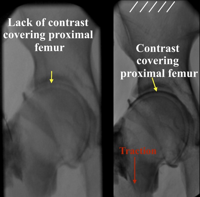
Fluoroscopic images of a hip without (left image) and with (right image) the application of manual traction.
Fig. 7.
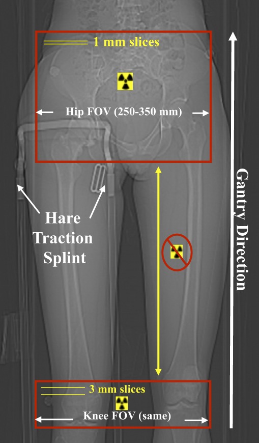
Computed tomography scout view of a study patient. FOV = field of view.
Fig. 8.

Coronal computed tomographic images of a hip without (left image) and with (right image) traction applied. Contrast agent clearly covers the entire proximal portion of the femur when the hip is under traction, thus improving image quality and the ability to delineate pelvic cartilage from femoral cartilage.
Three-Dimensional Model Reconstruction
Digital Imaging and Communications in Medicine (DICOM; National Electrical Manufacturers Association, Rosslyn, Virginia) images were imported into commercial software (Amira 5.2.1; Visage Imaging, San Diego, California). Semiautomatic segmentation was used to outline cortical bone, the cortical-trabecular bone boundary, and cartilage44. The segmented splines were triangulated into a three-dimensional reconstruction with use of Delaunay triangulation45. Minor smoothing and decimation were performed to eliminate noticeable segmentation and imaging artifact (e.g., the blocky piecewise regions known as staircase artifact) (Fig. 9). The entire three-dimensional reconstruction process has been validated previously46,47. Briefly, the error between true anatomy and three-dimensional reconstruction has been shown to be <3%45. In addition, cartilage that is >1.0 mm thick has been shown to be accurately (i.e., with <10% error) reconstructed from computed tomographic arthrography images46 (Fig. 10).
Fig. 9.

Three-dimensional models are generated from computed tomographic arthrography image data on a patient-specific basis with use of Amira 5.2. Example of this process for a patient with classic dysplasia. From left to right: a screen shot of the program, showing the outline for the pelvic cortex (coronal plane). Segmented splines are triangulated into a surface, which is then smoothed and decimated to remove digitization and computed tomography staircase artifacts.
Fig. 10.

Plot of cartilage thickness in a normal human femur (left) and acetabulum (right). The reconstruction error for cartilage has been shown to be <10% if the cartilage is >1.0 mm thick. The color bar indicates the cartilage thickness as it varies by color that is represented on the bar from 0.8 mm to 2.0 mm thick.
As part of our ongoing “patient-specific preoperative planning guide,” a detailed report was presented to the surgeon and included: (1) a computed tomographic arthrography radiology report (the degree of acetabular retroversion, femoral anteversion, the presence of labral tears, lesions, and alpha angles); (2) plain radiographic images and measurements and/or findings (the center-edge angle, the posterior wall sign, and the crossover sign); (3) a video of the three-dimensional model rotating in space (for full appreciation of anterior or posterior overcoverage or undercoverage); (4) localized asphericity of the femoral head; and (5) a color plot of cartilage thickness. Deviation of the femoral cortex from a perfect sphere was measured computationally, as determined with a least-squares regression analysis of the surface nodes for the patient's femoral head, with use of a previously validated algorithm44. Asphericity was presented as a color-plot scale, which quantitatively detailed the extent of bone to be removed to conform to a perfect sphere, along with the location of the bone in three-dimensional space (with positive deviations interpreted as “bone to be removed,” as measured in millimeters) (Fig. 11). Cartilage thickness was measured with use of a previously validated algorithm45.
Fig. 11.

Plot of asphericity of the femoral head. Left side of figure shows a hip with cam femoroacetabular impingement as compared with a normal joint. When rescaled (right side of figure), the normal joint continues to show very little deviation from a perfect sphere. (Note: positive deviations indicate “bone to be removed,” whereas negative deviations indicate bone indentations.)
Patient-Specific Finite-Element Analysis
Currently, we are converting our three-dimensional reconstructions of the hip joint into patient-specific finite-element models. Each finite-element model is “driven” with use of kinematic data acquired from a motion-analysis laboratory. The models include the varying thicknesses of the cartilage and the cortical bone and yield predictions of cartilage contact pressures, contact area, shear stresses, and bone mechanics (Figs. 12 and 13). This approach to patient-specific finite-element modeling has been validated previously with use of subject-specific (cadaver) finite-element models44,45. It is anticipated that, along with computed tomographic arthrography, plain radiographic measurements, and three-dimensional-model measurements, a patient-specific approach to modeling the mechanics of hip dysplasia and femoroacetabular impingement will allow us to compare normal versus pathomorphologic hips to develop a quantitative understanding of how geometrical deformities predispose the hip to early onset osteoarthritis.
Fig. 12.

Patient-specific finite-element mesh of a normal human hip. Image at left side of figure shows femoral detail with use of finite-element mesh, showing cortical bone and cartilage. The cartilage has been modeled with varying thickness as segmented from the computed tomography images. Middle images show how cortical bone is modeled with use of shell elements with position-dependent thickness, which is also based on the computed tomography image data. Image at right shows the magnitude and distribution of cartilage contact pressures in a normal acetabulum during simulated descent of stairs.
Fig. 13.

Comparison of cartilage contact pressures between a normal (top row) and a dysplastic (bottom row) hip joint. Pressures remain elevated in the dysplastic joint during simulated walking, stair-climbing, and descent of stairs.
Clinical Application of Three-Dimensional Imaging
The imaging protocol for selected young-adult patients with dysplasia and femoroacetabular impingement at our institution now includes a detailed analysis of the plain radiography, computed tomographic arthrography, and three-dimensional computational model data in a concise portable document format (PDF), thus enabling the treating physician to fully characterize the pathomorphology of individual hips and to create an appropriate treatment plan. The case examples below illustrate the value of a comprehensive imaging protocol accentuated with three-dimensional imaging.
Contemporary Preoperative Planning
Case Examples
Case 6. Acetabular Retroversion Treated with a Periacetabular Osteotomy
An eighteen-year-old man who had previously undergone surgical dislocation and osteochondroplasty of the left hip to treat femoroacetabular impingement presented with symptoms of femoroacetabular impingement of the right hip. Radiographs revealed acetabular retroversion with a positive posterior wall sign and a visible ischial spine. Three-dimensional modeling confirmed an acetabular posterior wall deficiency with intact hyaline cartilage. Treatment consisted of an anteversion-producing periacetabular osteotomy and femoral head-neck osteochondroplasty for the purpose of improving offset (Figs. 14-A through 14-D).
Fig. 14.

Case 6. A: Anteroposterior pelvic radiograph illustrating acetabular retroversion and a positive posterior wall sign in the right hip. B: False-profile lateral radiograph of the right hip, illustrating anterior acetabular overcoverage. C: Three-dimensional computational model confirming acetabular retroversion of the right hip with a reduced femoral head-neck offset. The red dotted lines on the right hip show the area that has reduced head-neck offset. The red dotted line on the left hip shows the new head-neck contour. Postsurgical correction of femoral head-neck offset is confirmed in the left hip. D: Three-dimensional computational model demonstrating the posterior wall deficiency of the left hip.
Case 7. Legg-Calvé-Perthes Disease with a Femoral Osteochondral Lesion
An eighteen-year-old man with a history of Legg-Calvé-Perthes disease presented with symptoms of femoroacetabular impingement of the left hip. Magnetic resonance arthrography images showed evidence of loose osteochondral bodies within the joint. Computed tomographic arthrography and three-dimensional modeling confirmed the femoral deformity that is typically associated with Legg-Calvé-Perthes disease and osteochondral head fragmentation. Treatment consisted of relative lengthening of the femoral neck and grafting of the femoral-head defect with osteochondral tissue that had been resected from the head-neck junction. Acetabular hyaline cartilage delamination (Outerbridge grade IV48) was treated with acetabular rim resection and labral refixation (Figs. 15-A through 15-D).
Fig. 15.

Case 7. A: Anteroposterior pelvic radiograph demonstrating coxa magna, coxa brevis, and a sagging rope sign50 of the left hip. B: Three-dimensional computational model confirming a Legg-Calvé-Perthes-like deformity of the left hip. C: Intraoperative photograph at the time of surgical dislocation, illustrating osteochondroplasty of the anterior femoral head. D: Intraoperative photograph after osteochondral autografting of the lesion in the femoral head.
Three-Dimensional Imaging and Complex Pathomorphology
The value of three-dimensional imaging is perhaps best appreciated in complex cases of hips with extreme variations in femoral and acetabular morphology. The cases highlighted below represent challenging treatment dilemmas. The ultimate decision to select acetabular reorientation or osteochondroplasty was facilitated by the three-dimensional images of these hips.
Case 8. Profound Acetabular Retroversion and Normal Lateral Coverage
A seventeen-year-old man presented with symptoms of femoroacetabular impingement. Radiographs showed severe caudal crossover signs, and two-dimensional computed tomograms showed 25° of acetabular retroversion. Three-dimensional modeling clearly demonstrated a posterior acetabular wall deficiency, normal lateral coverage, and a relative lack of head-neck offset. Treatment consisted of a bilateral staged anteversion-producing periacetabular osteotomy with special care taken to avoid lateral overcoverage while improving posterior coverage six months apart (Figs. 16-A through 16-D).
Fig. 16.

Case 8. A: Anteroposterior pelvic radiograph demonstrating profound acetabular retroversion of both hips. B: False-profile lateral radiograph illustrating profound anterior acetabular overcoverage. C: Translucent three-dimensional computational model demonstrating substantial acetabular retroversion. D: Three-dimensional computational model confirming a deficient posterior wall of the acetabulum.
Case 9. Combined Cam-and-Pincer Impingement
A thirty-five-year-old man presented with symptoms of femoroacetabular impingement. Radiographs demonstrated combined cam-and-pincer femoroacetabular impingement. Three-dimensional modeling demonstrated acetabular retroversion and poor femoral head-neck offset. Treatment, which consisted of surgical dislocation and osteochondroplasty, excision of delaminated hyaline cartilage from the one o'clock position to the three o'clock position with rim resection at the same area, and labral refixation, resulted in improvement in femoral head-neck offset (Figs. 17-A through 17-E).
Fig. 17.

Case 9. A: Anteroposterior radiograph of the right hip, demonstrating acetabular retroversion and reduced femoral head-neck offset. B: Cross-table lateral radiograph demonstrating reduced femoral head-neck offset. C: T1-weighted magnetic resonance arthrogram demonstrating hyaline cartilage delamination. D: Three-dimensional computational model confirming acetabular retroversion and reduced femoral head-neck offset. E: Intraoperative photograph illustrating acetabular hyaline cartilage delamination from the one o'clock position to the three o'clock position.
Case 10. Combined Cam-and-Pincer Impingement
A twenty-three-year-old man presented with symptoms of femoroacetabular impingement in the left hip. Radiographs demonstrated signs of combined cam-and-pincer femoroacetabular impingement. Three-dimensional modeling demonstrated acetabular retroversion with a prominent os acetabuli and posterior deficiency. Treatment consisted of a periacetabular osteotomy, os excision, labral repair, and femoral head-neck osteochondroplasty of the left hip (Figs. 18-A through 18-E).
Fig. 18.

Case 10. A: Anteroposterior pelvic radiograph demonstrating acetabular retroversion and an os acetabuli. B: Frog-leg lateral radiograph illustrating an os acetabuli and mildly reduced femoral head-neck offset. C: Translucent three-dimensional computational model demonstrating acetabular retroversion and a more pronounced reduced femoral head-neck offset (black arrow indicates the anterior wall of the acetabulum). D: Postoperative anteroposterior pelvic radiograph demonstrating improved acetabular position after the left periacetabular osteotomy. E: Intraoperative fluoroscopy image documenting improved femoral head-neck offset after osteochondroplasty of the femoral head-neck junction of the left hip.
Future Directions
Although the use of three-dimensional imaging has enhanced the diagnosis and treatment of patients with dysplasia and femoroacetabular impingement in our practice, the true utility of computational modeling and finite-element analysis applied on a subject-specific basis for these hips has far greater-reaching potential. With the recent emphasis on the limitations of two-dimensional imaging methods, including magnetic resonance arthrographic assessment of hip morphology36,47,49, it is logical that advancements in three-dimensional imaging along with utilization of and familiarity with this technology will bring a greater appreciation of complex hip pathomorphology. For example, the use of the color-plot scale to detail where the femoral head deviates from a sphere should be much more illustrative of the cam pathomorphology than a series of radial images requiring alpha-angle measurements would be36,47. Additionally, the described imaging techniques offer the potential to create a more three-dimensional-based classification system by correlating measurements unique to three-dimensional models (such as the percent of coverage of the femoral head, and quantified femoral asphericity), which may improve on current two-dimensional systems. Furthermore, patient-specific finite-element models—which can predict preoperative and postoperative cartilage contact mechanics, including accurate kinematics as quantified by biplane fluoroscopy—become possible with the described technology. Ultimately, hip-joint biomechanics quantified by patient-specific finite-element models that explicitly define the geometry of both cartilage and bone and are driven by accurate kinematics as quantified by high-speed digital fluoroscopy (walking on a treadmill and stair-climbing or descending) should provide information that will enhance our current understanding of abnormal hip-joint mechanics.
Discussion
Abnormal hip morphology may be the dominant cause of hip pain and the subsequent development of osteoarthritis of the hip in young adults. Hip pathomorphology may be manifested by femoral or acetabular deformity or malorientation. Most patients have a combination of deformity and malorientation. Surgical intervention should be focused on correction of the underlying pathomorphology as well as the resultant chondrolabral tissue damage. Three-dimensional computational modeling of the hip can facilitate proper identification of important pathomorphologic anatomy. Additionally, improved understanding of femoroacetabular impingement and dysplasia through three-dimensional computational modeling may facilitate new classification systems and the verification of treatment methodologies.
Disclosure: In support of their research for or preparation of this work, one or more of the authors received, in any one year, outside funding or grants in excess of $10,000 from NIH R01AR053344. Neither they nor a member of their immediate families received payments or other benefits or a commitment or agreement to provide such benefits from a commercial entity.
References
- 1.Ganz R, Parvizi J, Beck M, Leunig M, Nötzli H, Siebenrock KA. Femoroacetabular impingement: a cause for osteoarthritis of the hip. Clin Orthop Relat Res. 2003;417:112-20. [DOI] [PubMed] [Google Scholar]
- 2.Tannast M, Goricki D, Beck M, Murphy SB, Siebenrock KA. Hip damage occurs at the zone of femoroacetabular impingement. Clin Orthop Relat Res. 2008;466:273-80. [DOI] [PMC free article] [PubMed] [Google Scholar]
- 3.Leunig M, Beck M, Dora C, Ganz R. [Femoroacetabular impingement: trigger for the development of coxarthrosis]. Orthopade. 2006;35:77-84. German. [DOI] [PubMed] [Google Scholar]
- 4.Leunig M, Ganz R. [Femoroacetabular impingement. A common cause of hip complaints leading to arthrosis]. Unfallchirurg. 2005;108:9-10, 12-7. German. [DOI] [PubMed] [Google Scholar]
- 5.Tanzer M, Noiseux N. Osseous abnormalities and early osteoarthritis: the role of hip impingement. Clin Orthop Relat Res. 2004;429:170-7. [PubMed] [Google Scholar]
- 6.Beck M, Kalhor M, Leunig M, Ganz R. Hip morphology influences the pattern of damage to the acetabular cartilage: femoroacetabular impingement as a cause of early osteoarthritis of the hip. J Bone Joint Surg Br. 2005;87:1012-8. [DOI] [PubMed] [Google Scholar]
- 7.Pfirrmann CW, Mengiardi B, Dora C, Kalberer F, Zanetti M, Hodler J. Cam and pincer femoroacetabular impingement: characteristic MR arthrographic findings in 50 patients. Radiology. 2006;240:778-85. Erratum in: Radiology. 2007;244:626. [DOI] [PubMed] [Google Scholar]
- 8.Ganz R, Gill TJ, Gautier E, Ganz K, Krügel N, Berlemann U. Surgical dislocation of the adult hip: a technique with full access to the femoral head and acetabulum without the risk of avascular necrosis. J Bone Joint Surg Br. 2001;83:1119-24. [DOI] [PubMed] [Google Scholar]
- 9.Ganz R, Klaue K, Vinh TS, Mast JW. A new periacetabular osteotomy for the treatment of hip dysplasias. Technique and preliminary results. Clin Orthop Relat Res. 1988;232:26-36. [PubMed] [Google Scholar]
- 10.Peters CL, Erickson JA. Treatment of femoro-acetabular impingement with surgical dislocation and débridement in young adults. J Bone Joint Surg Am. 2006;88:1735-41. [DOI] [PubMed] [Google Scholar]
- 11.Holmich P, Dienst M. [Differential diagnosis of hip and groin pain. Symptoms and technique for physical examination]. Orthopade. 2006;35:8, 10-15. German. [DOI] [PubMed] [Google Scholar]
- 12.Philippon MJ, Maxwell RB, Johnston TL, Schenker M, Briggs KK. Clinical presentation of femoroacetabular impingement. Knee Surg Sports Traumatol Arthrosc. 2007;15:1041-7. [DOI] [PubMed] [Google Scholar]
- 13.Tannast M, Siebenrock KA, Anderson SE. Femoroacetabular impingement: radiographic diagnosis—what the radiologist should know. AJR Am J Roentgenol. 2007;188:1540-52. [DOI] [PubMed] [Google Scholar]
- 14.Fadul DA, Carrino JA. Imaging of femoroacetabular impingement. J Bone Joint Surg Am. 2009;91 Suppl 1:138-43. [DOI] [PubMed] [Google Scholar]
- 15.Tannast M, Zheng G, Anderegg C, Burckhardt K, Langlotz F, Ganz R, Siebenrock KA. Tilt and rotation correction of acetabular version on pelvic radiographs. Clin Orthop Relat Res. 2005;438:182-90. [DOI] [PubMed] [Google Scholar]
- 16.Siebenrock KA, Kalbermatten DF, Ganz R. Effect of pelvic tilt on acetabular retroversion: a study of pelves from cadavers. Clin Orthop Relat Res. 2003;407:241-8. [DOI] [PubMed] [Google Scholar]
- 17.Mast JW, Brunner RL, Zebrack J. Recognizing acetabular version in the radiographic presentation of hip dysplasia. Clin Orthop Relat Res. 2004;418:48-53. [DOI] [PubMed] [Google Scholar]
- 18.Wiberg G. Shelf operation in congenital dysplasia of the acetabulum and in subluxation and dislocation of the hip. J Bone Joint Surg Am. 1953;35:65-80. [PubMed] [Google Scholar]
- 19.Reynolds D, Lucas J, Klaue K. Retroversion of the acetabulum. A cause of hip pain. J Bone Joint Surg Br. 1999;81:281-8. [DOI] [PubMed] [Google Scholar]
- 20.Jamali AA, Mladenov K, Meyer DC, Martinez A, Beck M, Ganz R, Leunig M. Anteroposterior pelvic radiographs to assess acetabular retroversion: high validity of the “cross-over-sign”. J Orthop Res. 2007;25:758-65. [DOI] [PubMed] [Google Scholar]
- 21.Bardakos NV, Villar RN. Predictors of progression of osteoarthritis in femoroacetabular impingement: a radiological study with a minimum of ten years follow-up. J Bone Joint Surg Br. 2009;91:162-9. [DOI] [PubMed] [Google Scholar]
- 22.Giori NJ, Trousdale RT. Acetabular retroversion is associated with osteoarthritis of the hip. Clin Orthop Relat Res. 2003;417:263-9. [DOI] [PubMed] [Google Scholar]
- 23.Siebenrock KA, Schoeniger R, Ganz R. Anterior femoro-acetabular impingement due to acetabular retroversion. Treatment with periacetabular osteotomy. J Bone Joint Surg Am. 2003;85:278-86. [DOI] [PubMed] [Google Scholar]
- 24.Kalberer F, Sierra RJ, Madan SS, Ganz R, Leunig M. Ischial spine projection into the pelvis: a new sign for acetabular retroversion. Clin Orthop Relat Res. 2008;466:677-83. [DOI] [PMC free article] [PubMed] [Google Scholar]
- 25.Clohisy JC, Nunley RM, Otto RJ, Schoenecker PL. The frog-leg lateral radiograph accurately visualized hip cam impingement abnormalities. Clin Orthop Relat Res. 2007;462:115-21. [DOI] [PubMed] [Google Scholar]
- 26.Meyer DC, Beck M, Ellis T, Ganz R, Leunig M. Comparison of six radiographic projections to assess femoral head/neck asphericity. Clin Orthop Relat Res. 2006;445:181-5. [DOI] [PubMed] [Google Scholar]
- 27.Chosa E, Tajima N. Anterior acetabular head index of the hip on false-profile views. New index of anterior acetabular cover. J Bone Joint Surg Br. 2003;85:826-9. [PubMed] [Google Scholar]
- 28.Lequesne M, de Sèze. [False profile of the pelvis. A new radiographic incidence for the study of the hip. Its use in dysplasias and different coxopathies]. Rev Rhum Mal Osteoartic. 1961;28:643-52. French. [PubMed] [Google Scholar]
- 29.Nötzli HP, Wyss TF, Stoecklin CH, Schmid MR, Treiber K, Hodler J. The contour of the femoral head-neck junction as a predictor for the risk of anterior impingement. J Bone Joint Surg Br. 2002;84:556-60. [DOI] [PubMed] [Google Scholar]
- 30.Petersilge CA, Haque MA, Petersilge WJ, Lewin JS, Lieberman JM, Buly R. Acetabular labral tears: evaluation with MR arthrography. Radiology. 1996;200:231-5. [DOI] [PubMed] [Google Scholar]
- 31.Schmid MR, Nötzli HP, Zanetti M, Wyss TF, Hodler J. Cartilage lesions in the hip: diagnostic effectiveness of MR arthrography. Radiology. 2003;226:382-6. [DOI] [PubMed] [Google Scholar]
- 32.Anderson LA, Peters CL, Park BB, Stoddard GJ, Erickson JA, Crim JR. Acetabular cartilage delamination in femoroacetabular impingement. Risk factors and magnetic resonance imaging diagnosis. J Bone Joint Surg Am. 2009;91:305-13. [DOI] [PubMed] [Google Scholar]
- 33.Beaulé PE, Zaragoza EJ. Surgical images: musculoskeletal acetabular cartilage delamination demonstrated by magnetic resonance arthrography: inverted “Oreo” cookie sign. Can J Sur. 2003;46:463-4. [PMC free article] [PubMed] [Google Scholar]
- 34.Myers SR, Eijer H, Ganz R. Anterior femoroacetabular impingement after periacetabular osteotomy. Clin Orthop Relat Res. 1999;363:93-9. [PubMed] [Google Scholar]
- 35.Johnston TL, Schenker ML, Briggs KK, Philippon MJ. Relationship between offset angle alpha and hip chondral injury in femoroacetabular impingement. Arthroscopy. 2008;24:669-75. [DOI] [PubMed] [Google Scholar]
- 36.Rakhra KS, Sheikh AM, Allen D, Beaulé PE. Comparison of MRI alpha angle measurement planes in femoroacetabular impingement. Clin Orthop Relat Res. 2009;467:660-5. [DOI] [PMC free article] [PubMed] [Google Scholar]
- 37.Neumann M, Cui Q, Siebenrock KA, Beck M. Impingement-free hip motion: the ‘normal’ angle alpha after osteochondroplasty. Clin Orthop Relat Res. 2009;467:699-703. [DOI] [PMC free article] [PubMed] [Google Scholar]
- 38.James SL, Ali K, Malara F, Young D, O'Donnell J, Connell DA. MRI findings of femoroacetabular impingement. AJR Am J Roentgenol. 2006;187:1412-9. [DOI] [PubMed] [Google Scholar]
- 39.Kassarjian A, Yoon LS, Belzile E, Connolly SA, Millis MB, Palmer WE. Triad of MR arthrographic findings in patients with cam-type femoroacetabular impingement. Radiology. 2005;236:588-92. [DOI] [PubMed] [Google Scholar]
- 40.Leunig M, Beck M, Kalhor M, Kim YJ, Werlen S, Ganz R. Fibrocystic changes at anterosuperior femoral neck: prevalence in hips with femoroacetabular impingement. Radiology. 2005;236:237-46. [DOI] [PubMed] [Google Scholar]
- 41.Gdalevitch M, Smith K, Tanzer M. Delamination cysts: a predictor of acetabular cartilage delamination in hips with a labral tear. Clin Orthop Relat Res. 2009;467:985-91. [DOI] [PMC free article] [PubMed] [Google Scholar]
- 42.Klaue K, Durnin CW, Ganz R. The acetabular rim syndrome. A clinical presentation of dysplasia of the hip. J Bone Joint Surg Br. 1991;73:423-9. [DOI] [PubMed] [Google Scholar]
- 43.Espinosa N, Beck M, Rothenfluh DA, Ganz R, Leunig M. Treatment of femoro-acetabular impingement: preliminary results of labral refixation. Surgical technique. J Bone Joint Surg Am. 2007;89(Suppl 2 Pt 1):36-53. [DOI] [PubMed] [Google Scholar]
- 44.Anderson AE, Ellis BJ, Maas SA, Peters CL, Weiss JA. Validation of finite element predictions of cartilage contact pressure in the human hip joint. J Biomech Eng. 2008;130:051008. [DOI] [PMC free article] [PubMed] [Google Scholar]
- 45.Anderson AE, Peters CL, Tuttle BD, Weiss JA. Subject-specific finite element model of the pelvis: development, validation and sensitivity studies. J Biomech Eng. 2005;127:364-73. [DOI] [PubMed] [Google Scholar]
- 46.Anderson AE, Ellis BJ, Peters CL, Weiss JA. Cartilage thickness: factors influencing multidetector CT measurements in a phantom study. Radiology. 2008;246:133-41. [DOI] [PMC free article] [PubMed] [Google Scholar]
- 47.Dudda M, Albers C, Mamisch TC, Werlen S, Beck M. Do normal radiographs exclude asphericity of the femoral head-neck junction? Clin Orthop Relat Res. 2009;467:651-9. [DOI] [PMC free article] [PubMed] [Google Scholar]
- 48.Cameron ML, Briggs KK, Steadman JR. Reproducibility and reliability of the Outerbridge classification for grading chondral lesions of the knee arthroscopically. Am J Sports Med. 2003;31:83-6. [DOI] [PubMed] [Google Scholar]
- 49.Clohisy JC, Carlisle JC, Trousdale R, Kim YJ, Beaule PE, Morgan P, Steger-May K, Schoenecker PL, Millis M. Radiographic evaluation of the hip has limited reliability. Clin Orthop Relat Res. 2009;467:666-75. [DOI] [PMC free article] [PubMed] [Google Scholar]
- 50.Apley AG, Wientroub S. The sagging rope sign in Perthes' disease and allied disorders. J Bone Joint Surg Br. 1981;63:43-7. [DOI] [PubMed] [Google Scholar]