Abstract
Cadaveric in vitro studies are essential to test hypotheses concerning surgical manipulations in the same individual. Robotic technologies as well as different knee-models have been developed to get an in-depth comprehension of knee joint kinematics. The purpose of this study was to compare utilization of these different established principles.
Ten human cadaveric knee specimens were used to measure the kinematics during a weight-bearing flexion in a 6-degrees-of-freedom knee simulator. While flexing the knee, joint quadriceps muscle forces were dynamically simulated to reach a vertical ground reaction force of 100N. Fourteen knee specimens were mounted in 6-degrees-of-freedom robotic manipulator with a universal force sensor. The unloaded flexing motion of each specimen was measured by finding positions for each degree of flexion where all forces are minimal (passive path). The kinematic data of the knee-simulator and the robot concerning internal-external rotation, anterior-posterior translation, varus-valgus motion, and medial-lateral translation was examined.
For all investigated degrees of freedom the kinematics of the robotic passive path differed from the loaded kinematics in the knee simulator.
Simulated bodyweight as well as the examination method used has a substantial influence on joint kinematics during flexion which has to be considered when interpreting biomechanical studies as well as clinical tests.
Key words: kinematics, knee, in vitro, passive path, weight-bearing.
Introduction
Many approaches have been used and described to explore and measure in vitro kinematics of the knee joint, which, due to its sophisticated composition, is difficult to reproduce.1 In vivo open-MRI or fluoroscopic studies measured the movement of the joint and described the anatomy of the bony structures very precisely. Their clear limitation is the lacking possibility to measure the same knee before and after surgical procedures or manipulations to find out about their implications on the knee.2 Computerized three dimensional models have been developed, which allow calculating differences after specific manipulations of the knee. They are restricted to the input of the developers and their conception of the situation. Thus they can only represent part of the real setting.3–5 So to date, in vitro examinations with human cadaver knees are the preferred way to gain reliable data. These in vitro studies clearly have limitations, but they are definitely useful in terms of obtaining clinical relevant insights to the effect of different surgical techniques. Earlier in vitro testing was conducted using simple test-rigs which could not resemble physiologic movement of the joints. As the electromechanical technology advances, sophisticated apparatus, such as motor-controlled test rigs6–9 and 6 DOF robotic technologies,10 are used nowadays to examine the kinematics of the knee with and without load. With this modern hardware a position- and force controlled motion path can be achieved. They allow measurement of kinematic data as well as precisely sense forces in all structures of the knee by the principle of superposition. To find out the physiologic unloaded motion of a specimen, a method called passive path (PP) has been established.11 It resembles a flexion movement where minimal internal forces in the knee are traced. This path can then be replayed for the specimen and effects of manipulations can be evaluated.
So far, no data exists to assess differences in the tibiofemoral kinematics between the knee flexion path generated by the upright test rig and the robotic manipulator methods. Therefore, the purpose of this study was to compare knee joint kinematics of these two different established principles.
Materials and Methods
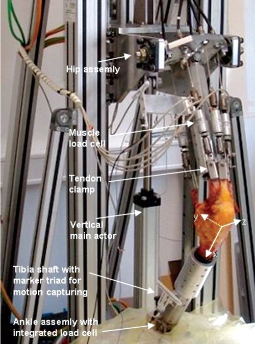
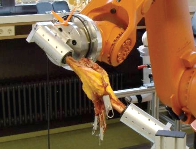
For a total of 24 cadaver knees which have been utilized in recent studies,12,13 the kinematic behaviour of PP knee flexion from 10 to 90 degrees have been compared between two different approaches: a loaded knee flexion (termed AF100 flexion) was performed using an upright knee simulator similar the Oxford Rig13 (Figure 1) and an unloaded knee flexion (termed PP flexion) was performed using a 6 DOF industrial robot with included universal force sensor (UFS)12 (Figure 2).
Figure 1.

Photo of the vertical upright knee simulator. A quasi statically muscle loaded knee flexion is simulated while descending the hip assembly by an electronically driven vertical actor. While lowering the main actuator quadriceps muscle forces where adjusted by feedback control according to the preset target value of the vertical load cell in the ankle assembly. Muscle force is generated by electrical servo motors attached to the muscles via custom made tendon clamps and measured by uniaxial load cells. The two hamstring muscles have been kept constant at 10 N. Movement of the femur and the tibia shaft is recorded simultaneously by marker triads belonging to an ultrasound motion capturing system. The orientation of the tibia coordinate system in an intermediate position is depicted.
Figure 2.

Photo of the robotic setup of the passive-path experiment. The robotic manipulator flexed the tibia from 0 to 90 degree in one degree increment while monitoring the force and moment of the UFS. At each flexion angle, the robotic manipulator adjusted its position until the force and moment in all degree-of-freedom except flexion-extension were reduced within 2 N and 0.2 Nm, respectively. The trajectory of these tibiofemoral equilibrium positions was defined as the passive path, which was then recorded by the robotic system.
For the upright knee simulator method, a squat-like knee flexion was simulated on 10 knee specimens (age: 70±15 years, mean±STD) with a flexion speed of 1 deg/s. Ground reaction force was quasi-statically maintained at approximately 100 N by feedback control of the tension on the three quadriceps actuators7 (Figure 1). For the robot experimental setup (Figure 2), PP knee flexion, where minimal internal forces in the knee are traced, were conducted on 14 knee specimens (age 75±13 years).12
All knee specimens had been fresh frozen and stored at −20°C. Prior to measurement, the specimens were defrosted over night and prepared. The femur and tibia were cut 15 cm from the joint line, and while the joint capsule and collateral ligaments were kept intact and five muscle tendons (rectus femoris, vastus lateralis, vastus medialis, semitendinosus, and biceps femoris) were exposed, all other skin and soft tissues were removed. The fibula was secured to the tibia with cortical screws to prevent its motion during the test. Both the femur and tibia were mounted onto a thick-walled steel cylinder by using a bone cement compound (polymethyl methacrylate) (Technovit 2060; Heraeus Kulzer, Hanau, Germany) and multiple accurately positioned set screws.
In order to compare the knee movement in both experimental setups the underlying coordinate systems have been specified consistently.
To define the body-fixed coordinate systems for the femur and tibia, we first recorded the positions of the medial and lateral prominences of the tibia plateau as reference points using a ZEBRIS® stylus pointer (ZEBRIS® CMS100, Isny, Germany) when the knee was fully extended. Both coordinate systems were assumed to be identical at full extension, and their common origins at full extension were defined as the midpoint of the two digitized reference points. For each of the tibial and femoral coordinate systems, the flexion axis (z-axis) was defined along the line between the two reference points. The y-axis was defined as a vector normal to a plane constructed by the z-axis and the longitudinal axis of the respective segment shafts. The x-axis was then defined by the cross product of the y and z axes. The femoral translation with respect to the tibia was defined as the position difference between the centers of the two moving coordinates, and the relative orientation of the tibia with respect to the femur was calculated in terms of Euler angles (rotation sequence: flexion-extension, abduction-adduction, internal external rotation).14
Data recording was carried out with a sampling rate of 1 Hz. Calculation of kinematic variables was done in equidistant steps of 1 deg by interpolation. Presentation of the data is done as diagrams in steps of 5 deg. Comparing the different experimental setups is done with unpaired two sided ttest at each flexion step (mean value±STD, asterisk for P<0.05).
The research presented in this work conforms to the Helsinki Declaration and to local legislation. It has been approved by the ethical committee of the medical faculty of the University of Tübingen.
Results
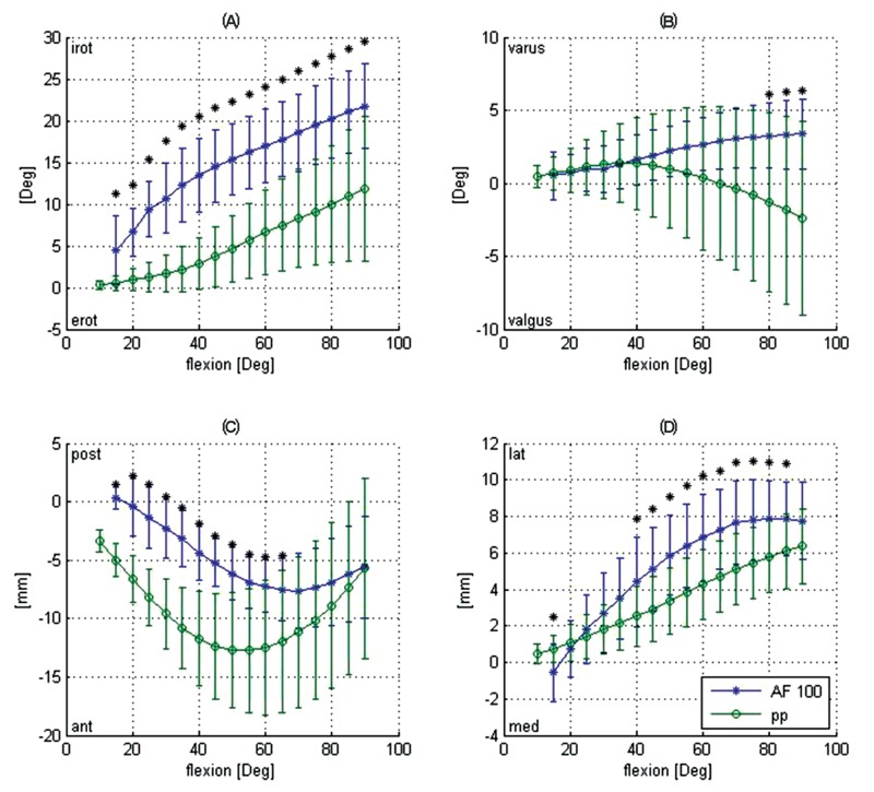
Comparing to the joint rotation in PP flexion, AF100 flexion leads to a significantly greater tibia internal rotation from 15 to 90 degrees of flexion. While the tibia internally rotates from 1 up to 12 degrees in PP flexion, the tibia internal rotation ranges from 5 to 22 degrees in AF100 flexion (Figure 3A). Although AF100 flexion resulted in less valgus rotation from 45 to 90 degrees of flexion, this difference was only statistically significant at high flexion angles (greater than 80 degrees: Figure 3B).
Figure 3.

Comparison of the kinematic measuring values between passive path (PP) and loaded knee squat (AF100). Tibial internal-external rotation A), tibial varus-valgus rotation B), femur anterior-posterior movement C) and femur medial-lateral movement D) versus flexion angle. (Mean value±STD, asterisk indicates P<0.05).
Comparing to the joint translation in PP flexion, AF100 leads to a significantly greater posterior femoral position up to 65 degrees of flexion with converging curves at 90 degrees of flexion (Figure 3C). Femoral medial-lateral translation is significantly different at 15 and between 40 and 85 degrees of flexion (Figure 3D).
Discussion
In our experimental setup, we compare the knee joint kinematics measured with (AF100 flexion) and without simulated muscle load (PP flexion). Our data show that kinematics of the knee joint measured by two different frequently used up-to-date devices differs strongly. This finding is not unexpected since it is a well known fact that simulated bodyweight has great influence on knee joint kinematics.7
Interestingly varus-valgus rotation significantly differed only between 80 and 90 degrees of flexion. This, in our opinion, shows that the collateral ligaments fulfil their function of stabilizing the knee joint in both devices. It also suggests that these ligaments are not much under strain with or without muscle load during a squatting motion.
While femur anterior-posterior movement differs more in low flexion angles, the femur medial-lateral difference has an opposite trend. Simulating muscle load leads to a relative posterior position of the femur from the beginning of the flexion range. However, the femoral rollback of the PP flexion is greater from 55 to 90 degrees of flexion and even leads to an intersection point of both AF100 and PP curves at 90 degrees. We contribute this to the fact that the position of the femur in AF100 flexion is predominantly determined by the simulated increasing muscle forces, while passive structures like the cruciate ligaments (specifically the posterior cruciate ligament) have greater influence in PP flexion.
Tibial rotation is the most influenced outcome measure by the simulated bodyweight. This may be because the increased muscle load during flexion leads to high contact forces within the tibiofemoral joint and thus overrides the effects of passive structures responsible for PP-kinematics. The shape of the PP-curve is in concordance with previous studies,15 although PP-kinematics has been shown to differ strongly from in vivo kinematics.16
In robotic cadaveric studies, PP is often used as baseline motion path before simulating bodyweight. This might be unfavourable because Li et al. have shown that applying bodyweight during PP-motion actually lead to tibial external rotation in higher flexion angles15 which is in contrast to PP-kinematics and other published in vivo and in vitro data.13,17
In conclusion our data show that simulated bodyweight as well as the examination method used has a substantial influence on the joint kinematics during flexion which has to be considered when interpreting biomechanical studies. The results from this study are also interesting from the clinician's point of view since they indicate that clinical tests on injured knees which are mostly done in a relaxed knee state may have to be considered carefully with respect to a muscle loaded knee movement. Beyond that, comparing our results of tibiofemoral kinematics for PP and AF100, the variance of all the PP-curves rises with higher flexion. This corresponds to the clinical observation, that the unloaded knee joint gets more unstable with rising flexion angles.
Acknowledgements:
we gratefully acknowledge the financial support of Smith & Nephew.
References
- 1.Walker PS, Haider H. Characterizing the motion of total knee replacements in laboratory tests. Clin Orthop Relat Res. 2003;410:54–68. doi: 10.1097/01.blo.0000063599.67412.44. [DOI] [PubMed] [Google Scholar]
- 2.Souza RB, Draper CE, Fredericson M, Powers CM. Femur rotation and patello-femoral joint kinematics: a weight-bearing magnetic resonance imaging analysis. J Orthop Sports Phys Ther. 2010;5:277–85. doi: 10.2519/jospt.2010.3215. [DOI] [PubMed] [Google Scholar]
- 3.Li G, Suggs J, Gill T. The effect of anterior cruciate ligament injury on knee joint function under a simulated muscle load: a three-dimensional computational simulation. Ann Biomed Eng. 2002;5:713–20. doi: 10.1114/1.1484219. [DOI] [PubMed] [Google Scholar]
- 4.Loch DA, Luo ZP, Lewis JL, Stewart NJ. A theoretical model of the knee and ACL: theory and experimental verification. J Biomech. 1992;1:81–90. doi: 10.1016/0021-9290(92)90247-x. [DOI] [PubMed] [Google Scholar]
- 5.Wehner T, Claes L, Simon U. Internal loads in the human tibia during gait. Clin Biomech. 2009;3:299–302. doi: 10.1016/j.clinbiomech.2008.12.007. [DOI] [PubMed] [Google Scholar]
- 6.D'Lima DD, Trice M, Urquhart AG, Colwell CW., Jr Comparison between the kinematics of fixed and rotating bearing knee prostheses. Clin Orthop Relat Res. 2000;380:151–7. doi: 10.1097/00003086-200011000-00020. [DOI] [PubMed] [Google Scholar]
- 7.Müller O, Lo J, Wünschel M, et al. Simulation of force loaded knee movement in a newly developed in vitro knee simulator. Biomed Tech. 2009;3:142–9. doi: 10.1515/BMT.2009.015. [DOI] [PubMed] [Google Scholar]
- 8.Wilson DR, Feikes JD, Zavatsky AB, O'Connor JJ. The components of passive knee movement are coupled to flexion angle. J Biomech. 2000;4:465–73. doi: 10.1016/s0021-9290(99)00206-7. [DOI] [PubMed] [Google Scholar]
- 9.Mizuno Y, Kumagai M, Mattessich SM, et al. Q-angle influences tibiofemoral and patellofemoral kinematics. J Orthop Res. 2001;5:834–40. doi: 10.1016/S0736-0266(01)00008-0. [DOI] [PubMed] [Google Scholar]
- 10.Fujie H, Mabuchi K, Woo SL, et al. The use of robotics technology to study human joint kinematics: a new methodology. J Biomech Eng. 1993;3:211–7. doi: 10.1115/1.2895477. [DOI] [PubMed] [Google Scholar]
- 11.Rudy TW, Livesay GA, Woo SL, Fu FH. A combined robotic/universal force sensor approach to determine in situ forces of knee ligaments. J Biomech. 1996;10:1357–60. doi: 10.1016/0021-9290(96)00056-5. [DOI] [PubMed] [Google Scholar]
- 12.Lo J, Müller O, Dilger T, et al. Translational and rotational knee joint stability in anterior and posterior cruciate-retaining knee arthroplasty. Knee. 2010 Nov 11; doi: 10.1016/j.knee.2010.10.009. [Epub ahead of print] 2010. [DOI] [PubMed] [Google Scholar]
- 13.Wünschel M, Müller O, Lo J, et al. The anterior cruciate ligament provides resistance to externally applied anterior tibial force but not to internal rotational torque during simulated weight-bearing flexion. Arthroscopy. 2010;11:1520–7. doi: 10.1016/j.arthro.2010.04.069. [DOI] [PubMed] [Google Scholar]
- 14.Grood ES, Suntay WJ. A joint coordinate system for the clinical description of three-dimensional motions: application to the knee. J Biomech Eng. 1983;2:136–44. doi: 10.1115/1.3138397. [DOI] [PubMed] [Google Scholar]
- 15.Li G, Zayontz S, DeFrate LE, et al. Kinematics of the knee at high flexion angles: an in vitro investigation. J Orthop Res. 2004;1:90–5. doi: 10.1016/S0736-0266(03)00118-9. [DOI] [PubMed] [Google Scholar]
- 16.Darcy SP, Rosvold JM, Beveridge JE, et al. A comparison of passive flexion-extension to normal gait in the ovine stifle joint. J Biomech. 2008;4:854–60. doi: 10.1016/j.jbiomech.2007.10.025. [DOI] [PubMed] [Google Scholar]
- 17.Li G, Papannagari R, Li M, et al. Effect of posterior cruciate ligament deficiency on in vivo translation and rotation of the knee during weightbearing flexion. Am J Sports Med. 2008;3:474–9. doi: 10.1177/0363546507310075. [DOI] [PubMed] [Google Scholar]


