Abstract
Diffusion is often the rate determining step in many biological processes. Currently, the two main computational methods for studying diffusion are stochastic methods, such as Brownian dynamics, and continuum methods, such as the finite element method. This paper proposes a new hybrid diffusion method that couples the strengths of each of these two methods. The method is derived for a general multidimensional system, and is presented using a basic test case for 1D linear and radially symmetric diffusion systems.
INTRODUCTION
Diffusion is an important factor in many biological processes, including protein-substrate reactions, protein-protein interactions,1, 2, 3 calcium channeling in cardiac myocytes,4, 5 the neuromuscular junction,6, 7, 8, 9 and the myelin sheath gap.10 Currently, there are two main methods used to study diffusion: stochastic methods, such as Brownian dynamics,11, 12, 13, 14, 15 and continuum methods, such as the finite element method.16 Each of these methods has its strengths and weaknesses, and can be more or less beneficial in different simulation situations.
The use of Brownian dynamics in computer simulations has been quite prevalent, with many available computational packages.17, 18, 19, 20, 21, 22 This method has the benefit of providing trajectories of the diffusing particle as it interacts with a target, and this method can be especially useful for looking at protein-protein interactions. However, since the usefulness of this method is based on statistics, many simulations must be run in order to have meaningful results. However, these calculations can take a significant amount of computational resources, especially when hundreds of thousands of simulations or long single simulations are required for sufficient statistical sampling. Some methods use multiple diffusing particles,21, 22, 23 and some consider only one moving particle at a time.17, 18, 19, 20
Whereas Brownian dynamics focuses on the movement of particular particles, the continuum methods can be used to study overall diffusion patterns exhibited by a collection of particles. One of the most popular continuum methods for biological systems is the finite element method.7, 8, 10, 24, 25, 26, 27 In this method, the region over which diffusion occurs is broken up into smaller simplices, and then the diffusion equation is solved over each simplex. Combining the results from the simplicies will result in the overall solution. The calculations for this type of model are relatively fast, once the initial setup of the system is complete. In addition, the finite element method works well for arbitrary geometries and the solutions are usually fairly accurate. This method has the benefit of simulating the ensemble behavior of many diffusing particles, instead of focusing on the motions of just a single particle. On the other hand, the trajectories of individual particles cannot be observed, which could be useful for understanding how a diffusing particle will find and interact with a target. The other major drawback of the finite element method is the need to create a grid or mesh of the diffusion domain by breaking it up into simplicies. While this process can be fairly easy for a simple domain, it is not a trivial task when dealing with even with a single protein at atomic resolution, because of the large number of small elements needed to resolve the complex shape of the molecular surface, and this difficulty would be compounded with larger systems such as subcellular compartments.
The goal of this paper is to present a new hybrid diffusion model that combines the best of both the Brownian dynamics and finite element methods. This model places a target particle at the center of the model, surrounded by a Brownian dynamics model with multiple diffusing particles. The Brownian dynamics region is itself surrounded by a finite element region. Although only the most basic cases are presented here, this model could potentially be useful in combing the best of both methods, by allowing atomistic detail of the target and the nearby diffusing particles, while allowing the speed of the finite element method to handle the calculations for a majority of the region of diffusion. This will also eliminate the problems of only being able to study one diffusing particle at a time and the need to generate a quality mesh of the receptor target.
This work continues the work of Gorba, Geyer, and Helms,22, 28, 29 who also have devised an interface between the continuum diffusion equation and Brownian dynamics for both steady-state and non-steady-state systems. Previous work also includes that of Im, Seefeld, and Roux,30 who have coupled Brownian dynamics with a particle reservoir described by a grand-canonical ensemble. Like the previous works, this work presents systems that are mathematically 1D in the continuum domain, but the algorithm formulation in terms of finite elements can be directly applied to higher dimensional systems. For formulating the finite element equations, we draw upon finite element solutions of non-steady-state diffusion equations in biophysical settings.7, 8, 25
THEORETICAL BACKGROUND
The goal of this method is to solve the diffusion equation
| (1) |
where c is the concentration, T is temperature, D is diffusion matrix, and F is force on particles as a function of position.
The solution of this equation can be described as a cloud of particles moving according to the stochastic differential equation given by
| (2) |
where w is a vector of independent Gaussian random variables with a zero mean and unit variance.
The solution to Eq. 1 can also be described by dividing the spatial domain into simplicies and defining hat functions on each node between the simplicies. A hat function has a value of 1 at the node and 0 at all other nodes, and varies linearly across the simplex. Assuming that the force and the diffusivity vary only with position and not time, and denoting the hat function centered at node i as ui, the diffusion equation can be multiplied by ui and with the use of Green's theorem, the weak formulation is obtained:
| (3) |
Next, it is assumed that concentration can be represented using the hat functions ui:
| (4) |
Equation 3 can then be written as a set of ordinary differential equations with coefficients ci:
| (5) |
The integrals involving the pairs of hat functions can be computed before the simulation. The results can be expressed analytically if the simplices are small enough so that the diffusivity and force can be assumed to be linear across each simplex, since this involves integration of polynomials over simplicies. Dirichlet, Neumann, and Robin boundary conditions can be expressed as linear equations in terms of the coefficients ci. Equation 5 in conjunction with the boundary conditions given above can be expressed in matrix form as
| (6) |
where b is a constant vector that depends on the boundary conditions. Because each hat function has local support and overlaps only a few neighbors, the matrices A and B are sparse.
In order to step this equation forward in time, the backward Euler method can be used:
| (7) |
where the index n represents progress through time. This equation can be re-written as
| (8) |
which can be used to calculate the diffusion over the finite element region at each time step in the simulation. The sparsity of the matrices allows rapid solution of Eq. 8.
COUPLING METHOD
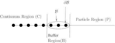
Now that we have the theoretical framework, the goal is to couple the stochastic model, given by Eq. 2, and the continuum model, which can be solved using Eq. 8. The first case that will be examined is diffusion in a 1D linear system. In order to couple these methods, the diffusion space must be divided into three regions: the continuum region (C), the particulate region (P), and a buffer regions (B) (Figure 1). The continuum region C consists of finite element simplices. The particulate region P consists of a region occupied only by discrete particles governed by the stochastic diffusion equation. The buffer region lies between the continuum and particulate regions and consists of a relatively small number of finite element simplices, and also contains particles. The nodes which border only simplicies in region B are denoted as set B, and the subset of B of nodes that directly border the particulate region is denoted as .
Figure 1.
Diagram of the continuum, buffer, and particle regions. The nodes are represented as dots on the line.
In order to transfer the particle concentration from the continuum region to the particulate region, a Dirichlet boundary condition of zero concentration is imposed on the nodes of . Before each time step, the concentration of the nodes in B is zero. Then, using a suitable time step Δt, the continuum region and particles are stepped forward in time using Eqs. 8, 2, respectively. If the model describing the particulate region has any features that result in the removal of particles, such as a reactive region or absorbing boundary, any particles that meet such criteria for removal are removed at this time.
After the forward time step, some particles may have wandered into the continuum region C. These are absorbed into the continuum hat functions, with the coefficients increased accordingly. Once the particle is absorbed, its weight is divided among the N + 1 nodes that border the simplex containing the particle in a manner that best preserves the original location of the particle. Before the simulation starts, the zeroth and first moment for each hat function is computed and stored:
| (9) |
| (10) |
If N + 1 weights wi are added to the N + 1 surrounding hat functions, then the first moment induced by the weights is given by
| (11) |
Using the rule that the moment in Eq. 11 be equal to the position of the particle,
| (12) |
provides N equations. One more equation is needed to determine N + 1 weights; this is provided by the condition that the weights sum to 1:
| (13) |
Equations 12, 13 are solved to obtain weights, the coefficient at each node is augmented by its corresponding weight, and the particle is removed.
Once the continuum and the particles have been stepped forward, the coefficients at the nodes of B – are no longer zero. Each hat function, weighted by its coefficient, is converted into zero or more particles. To do this, the number of particles generated by the hat function is computed by
| (14) |
The factor α allows one to create “particles” that represent fractional amounts of material. Using a large factor and thus a large number of particles can be useful for reducing the amount of noise introduced by using the stochastic simulation. From a physical viewpoint, this is acceptable because the particles do not interact with each other in this model. In a more physically realistic system in which each particle corresponds to a physical particle, this parameter must be consistent with the units used for ci. If the concentration is expressed in terms of number of particles per unit volume, then α is 1.
The particle creation step generally results in a non-integer number, but this number is then “stochastically rounded” to avoid fractional particles. The number nf is rounded by computing the fractional part f, and rounding up with probability f or rounding down otherwise. Any particles that are generated must then be placed in the system. This is done by treating the normalized hat functions ui/pi as a probability distribution function and sampling it, usually by using the rejection method. The node coefficients are then set to zero.
One possible source of error could occur during the stepping forward of the continuum equations and the absorption of material at the boundary defined by . This causes a net loss of material from the system and violates the conservation of matter. Therefore, this must be minimized by constructing the buffer region to have several layers of simplices between the particulate and continuum regions. Since the node coefficients ci are zero at the start of the time step, using a time step that is small compared to the time scale of diffusion across the smallest simplex ensures that the loss of material is negligible. This is demonstrated in the Appendix by a simple model.
1D LINEAR EXAMPLE PROBLEM
For the example problem solved by the hybrid method, a 1D linear domain was considered, with x ranging from 0 to 1. At x = 0, the concentration was fixed to be 1. The other side of the domain acted as an absorbing boundary; the concentration at x = 1 was fixed at 0. The initial conditions had a concentration of 0 throughout the domain, with diffusivity constant D = 1. The continuum region C occupied the interval , and was subdivided into 9 elements, each of length . The particulate region P occupied the interval . The buffer region B comprised three elements, each of length . For this simulation, the time step size was 0.000625, and the factor α was 1000. The time step size was calculated using the equation
| (15) |
where h is the width of each element (in this case ). Basing the time step size on the element width size ensures that the concentration from the continuum region will not advance too quickly and be absorbed into the buffer region at dB.
For the particles, the time step size was reduced when they were near the absorbing boundary. Each time step, obtained from Eq. 15, was subdivided into intervals less than or equal to a time step from
| (16) |
where x is the distance from the boundary. The particles that were close enough so that Δtsub was less than Δt were individually stepped forward using the smaller time step. This helped resolve the absorbing boundary more precisely and led to more accurate fluxes. It must be noted that in physically realistic systems, the use of very small time steps violates the assumption behind the derivation of the Brownian dynamics equation (Eq. 2) from molecular systems with inertia,11 and using such small time steps could be controversial. In the models under consideration here, though, these small steps are used merely to solve a model mathematical problem.
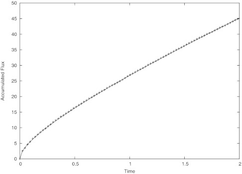
The analytical series solution to this problem can be shown to be31
| (17) |
where N is the accumulated flux.
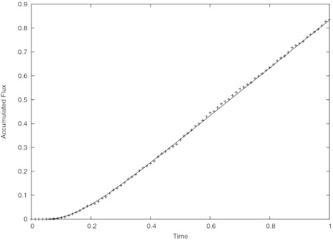
Figure 2 shows good agreement between the computed accumulated flux and series solution.
Figure 2.
Plot of accumulated flux vs. time. The solid line is the analytical solution and the data points represent the computation.
1D RADIAL HYBRID METHOD
The method of the radial hybrid calculations is entirely similar to that for the 1D linear system, but the governing equations are different. Thus, the calculations are reformatted below.
The radial diffusion equation is given by
| (18) |
For the sample problem being solved, the boundary conditions are given by
| (19) |
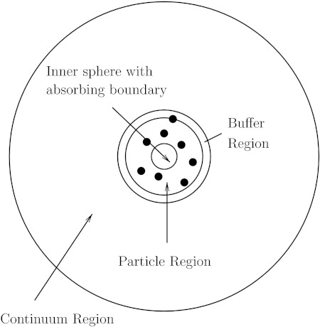
where r1 is the inner absorbing boundary, r2 is the outer boundary of the system, and cb is the value of the fixed concentration at the outer boundary. As above, the entire problem is divided into a finite element, buffer, and particle regions, as shown in Figure 3.
Figure 3.
Diagram of the radially symmetric finite element and particle hybrid model. The innermost region is a sphere with absorbing boundary conditions. The particle region, the buffer region, and the continuum region surround the sphere.
For the particle region, the particles are simulated in three dimensions using Eq. 2.
The finite element region is solved in a similar manner to the 1D solution, as shown in Sec. 2 of the paper, using the Galerkin method:
| (20) |
Through the use of the chain rule and integration by parts, and once again using ui to represent the hat functions, it can be shown that this simplifies to
| (21) |
Representing the concentration using hat functions
| (22) |
Equation 21 can now be written as
| (23) |
where
| (24) |
Thus, Eq. 23 can be written as
| (25) |
This can be written in matrix form as given in Eq. 7. Once the integrals given in Eq. 24 have been solved analytically, this calculation proceeds exactly as demonstrated in the 1D linear case.
Results
The sample problem for this case was solved over a 1D spherically symmetric domain where r1 = 1 and r2 = 10. At r2, the concentration was fixed to be 1 and at the absorbing boundary r1, the concentration was fixed at 0. Once again the initial conditions had a concentration of 0 throughout the domain, with diffusivity constant D = 1.
In this case, the nodes were spherical surfaces, and the finite elements were spherical shells with a hat profile. The continuum region C was subdivided into 39 elements with 0.18 length units between each node. In this case, the buffer region B comprised three elements. The time step was calculated using Eq. 15 above, and the factor α was set to 10. The analytical solution for the accumulated flux across the boundary at time t is given by31
| (26) |
where Jss is the steady-state flux:
| (27) |
Figure 4 shows good agreement between the analytical solution and calculated accumulated flux.
Figure 4.
Plot of accumulated flux vs. time for the first spherically symmetric case with initial zero concentration. The solid line is the analytical solution and the data points represent the computation.
1D SPHERICAL EXAMPLE WITH UNEVENLY SPACED SYMMETRIC ELEMENTS
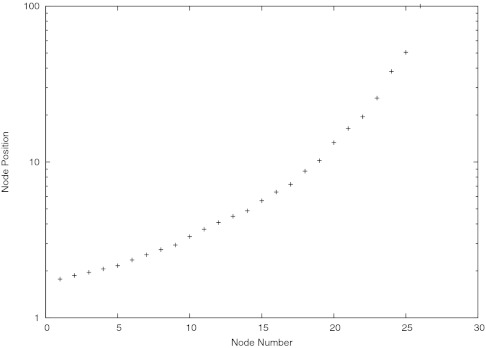
With the goal of eventually using this method to study more complicated realistic systems, the spherical simulation was altered to allow for a non-uniform grid of the diffusion domain. For this sample problem, the diffusion domain was much larger, with r1 = 1 and r2 = 100. In this case, the initial conditions set the initial concentration at c = 1 throughout the diffusion domain. The node positions were assigned according to the positions described in Figure 5 in which the nodes are numbered starting at 1 with the closest one to the absorbing sphere. In this case, there were three elements in the buffer region B. The elements were generated by starting with the interval (1, 100), and assigning values to the endpoints from the known steady-state solution c = 1 − r1/r. A linear interpolation was constructed on the interval, and if the maximum relative difference between the interpolation and the steady-state was greater than 0.01, the interval was divided in half, with a value from the steady-state solution assigned to the new point. The new intervals were recursively divided in the same manner until no more divisions occurred. This procedure assigns smaller finite elements to regions where the concentration is expected to vary more strongly across distance. Three of the intervals, encompassing the distance about 1.8–2 length units from the center of the sphere, were designated as the buffer region, and the intervals closer to the sphere than the buffer region were removed from consideration. The time step size from Eq. 15 was based on the most narrow finite element, and the factor α was set to 100.
Figure 5.
Graph showing node positions for unevenly spaced nodes.
This case approximately solves the unsteady-state Smoluchowski problem in which a reactive sphere is placed in an infinite, uniform sea of diffusing substrate points. Because the outer boundary is very far compared to the sphere radius, the solution obtained should be very similar to that with a boundary at infinity.
The analytical solution for this case is31
| (28) |
The results for the flux calculations can be seen in Figure 6.
Figure 6.
Plot of flux vs. time for the case of unevenly spaced nodes and initial uniform concentration. The solid line shows the analytical solution and the data points represent the computation.
DISCUSSION AND CONCLUSION
As demonstrated by the examples above, the results from this method closely match the analytical solutions of the time course of consumed material. Although the flux has temporal fluctuations due to the discrete particles, the fluctuations are smoothed out by the integration of the flux. The method's limitations include the approximations and limitations inherent in both finite element and Brownian dynamics methods. The only additional approximation introduced is the small loss of material at one of the interfaces between the continuum and particulate regions, and this approximation can be controlled as described in the Appendix. Even though this method can be used as a multiscale method, with finite elements describing the coarser domains and Brownian dynamics describing the finer domains, another limitation arises from the fact that the size of the time step taken is still limited by the finer domains, namely, the motion of the individual particles and the finite elements in the buffer region. Additional methodology development using stiff time integrators32 might allow this limitation to be overcome.
Finally, further development will be needed to study high concentrations of interacting particles. Currently, one can include interparticle interactions in both finite element computations10, 26 and Brownian dynamics simulations, as long as they are not run together as in the proposed method. One can also include external forces on the particles, as seen in the equations above. The missing link is a method to compute interparticle interactions between the particulate and continuum regions; this will be the subject of future work.
Although the examples provided in this paper are quite basic, this methodology will be further implemented to study much more complex systems. One goal is to use receptor crystal structures with specified active sites at the center of the diffusive system, surrounded by a small stochastic region which is then surrounded by a much larger continuum region on the cellular level. The diffusion domain can have arbitrary complexity in its geometry and boundary conditions; it is not limited to spherically symmetric geometries such as those used in current Brownian dynamics software packages for determining reaction rates.17, 18, 19, 20 One system of great interest is that of calcium ion diffusion in the cardiac myocyte,4, 5, 33 the diffusion domain can be constructed from light and electron microscopy data,33 while the calcium transporters and receptors can included in atomic detail for Brownian dynamics.34 Other systems of interest include diffusion of acetylcholine in the neuromuscular junction6, 7, 8, 9 and the diffusion of sodium and potassium ions in the node of Ranvier.10 Because such systems have multiple length and time scales, hybrid methods that can combine different algorithms and take advantage of their respective strengths will be useful for predicting and studying physiologically significant rates, fluxes, and currents.
ACKNOWLEDGMENTS
The work at UCSD was supported in part by NIH, NSF, HHMI, CTBP, NBCR, and the UCSD Chancellor's Interdisciplinary Collaboratories Fellowship.
APPENDIX: DEMONSTRATION OF NEGLIGIBLE LOSS OF MATERIAL
In order to demonstrate that a negligible amount of material is lost in this method, we set up a 1D interval L units wide, with concentration c held at c0 at the left side (x = 0) and zero at the right x = L. Since our examples have used buffer regions that are three elements wide, we assume three intervals, each L/3 units wide. Using Eq. 15 gives a time step of , where D is the constant diffusivity. Using separation of variables gives the concentration as a function of position and time:31
| (A1) |
We compute the amount of matter lost at the right boundary between zero time and the time step value relative to the amount of matter that remains in the interval after the time step.
| (A2) |
Applying this to the expression for the concentration and plugging in the value for Δt give the fraction 1.2 × 10⁻⁵. Thus, this approximation is controllable by having a sufficiently wide buffer region.
The question then arises: why not eliminate the loss altogether by using a no-flux boundary condition between the buffer and particulate regions? With our present geometry, this would probably cause only a very small distortion in the average position of the material. However, if this boundary effect were to become significant, for example, because of large forces or long-running equilibrium simulations, it would be necessary to devise a method for converting absorbed material into particles at the boundary. It is not as clear how one would handle a no-flux condition. This is our justification for currently using an absorbing rather than a no-flux boundary condition.
References
- Ouporov I., Knull H., Huber A., and Thomasson K., Biophys. J. 80, 2527 (2001). 10.1016/S0006-3495(01)76224-8 [DOI] [PMC free article] [PubMed] [Google Scholar]
- Spaar A., Dammer C., Gabdoulline R. R., and Wade R. C., Biophys. J. 90, 1913 (2006). 10.1529/biophysj.105.075507 [DOI] [PMC free article] [PubMed] [Google Scholar]
- Northrup S., Boles J., and Reynolds J., J. Chem. Phys. 91, 5991 (1987). 10.1021/j100307a036 [DOI] [Google Scholar]
- Hake J. and Lines G. T., Biophys. J. 94, 4184 (2008). 10.1529/biophysj.106.103523 [DOI] [PMC free article] [PubMed] [Google Scholar]
- Lu S., Michailova A., Saucerman J., Cheng Y., Yu Z., Kaiser T., Li W., Bank R., Holst M., McCammon J., Hayashi T., Hoshijima M., Arzberger P., and McCulloch A., IEEE Eng. Med. Biol. Mag. 28, 46 (2009). 10.1109/MEMB.2009.931787 [DOI] [PMC free article] [PubMed] [Google Scholar]
- Bartol T., Land B., Salpeter E., and Salpeter M., Biophys. J. 59, 1290 (1991). 10.1016/S0006-3495(91)82344-X [DOI] [PMC free article] [PubMed] [Google Scholar]
- Smart J. and McCammon J., Biophys. J. 75, 1679 (1998). 10.1016/S0006-3495(98)77610-6 [DOI] [PMC free article] [PubMed] [Google Scholar]
- Tai K., Bond S., MacMillan H., Baker N., Holst M., and McCammon J., Biophys. J. 84, 2234 (2003). 10.1016/S0006-3495(03)75029-2 [DOI] [PMC free article] [PubMed] [Google Scholar]
- Antosiewicz J., Gilson M. K., Lee I. H., and McCammon J. A., Biophys. J. 68, 62 (1995). 10.1016/S0006-3495(95)80159-1 [DOI] [PMC free article] [PubMed] [Google Scholar]
- Lopreore C. L., Bartol T. M., Coggan J. S., Keller D. X., Sosinsky G. E., Ellisman M. H., and Sejnowski T. J., Biophys. J. 95, 2624 (2008). 10.1529/biophysj.108.132167 [DOI] [PMC free article] [PubMed] [Google Scholar]
- Ermak D. and McCammon J., J. Chem. Phys. 69, 1352 (1978). 10.1063/1.436761 [DOI] [Google Scholar]
- Northrup S., Allison S., and McCammon J., J. Chem. Phys. 80, 1517 (1984). 10.1063/1.446900 [DOI] [Google Scholar]
- Zhou H., J. Chem. Phys. 92, 3092 (1990). 10.1063/1.457907 [DOI] [Google Scholar]
- Luty B., McCammon J., and Zhou H., J. Chem. Phys. 97, 5682 (1992). 10.1063/1.463777 [DOI] [Google Scholar]
- Bauler P., Huber G., Leyh T., and McCammon J. A., J. Phys. Chem. Lett. 1, 1332 (2010). 10.1021/jz1002007 [DOI] [PMC free article] [PubMed] [Google Scholar]
- Song Y., Zhang Y., Shen T., Bajaj C., McCammon J., and Baker N., Biophys. J. 86, 2017 (2004). 10.1016/S0006-3495(04)74263-0 [DOI] [PMC free article] [PubMed] [Google Scholar]
- Huber G. A. and McCammon J. A., Comput. Phys. Commun. 181, 1896 (2010). 10.1016/j.cpc.2010.07.022 [DOI] [PMC free article] [PubMed] [Google Scholar]
- Gabdoulline R. and Wade R., Biophys. J. 72, 1917 (1997). 10.1016/S0006-3495(97)78838-6 [DOI] [PMC free article] [PubMed] [Google Scholar]
- Northrup S., Laughner T., and Stevenson G., ‘MACRODOX macromolecular simulation program, Department of Chemistry, Tennessee Technological University, Cookeville, TN, 1997; online at iweb.tntech.edu/macrodox/macrodox.html.
- Madura J., Briggs J., Wade R., Davis M., Luty B., Ilin A., Antosiewicz J., Gilson M., Bagheri B., Scott L., and McCammon J., Comput. Phys. Commun. 91, 57 (1995). 10.1016/0010-4655(95)00043-F [DOI] [Google Scholar]
- Dlugosz M., Zielinski P., and Trylska J., J. Comput. Chem. 32, 2734 (2011). 10.1002/jcc.21847 [DOI] [PubMed] [Google Scholar]
- Geyer T., BMC Biophys. 4, (2011). 10.1186/2046-1682-4-7 [DOI] [PMC free article] [PubMed] [Google Scholar]
- McGuffee S. R. and Elcock A. H., PLoS Comput. Biol. 6, e1000694 (2010). 10.1371/journal.pcbi.1000694 [DOI] [PMC free article] [PubMed] [Google Scholar]
- Cheng Y., Suen J. K., Zhang D., Bond S. D., Zhang Y., Song Y., Baker N. A., Bajaj C. L., Holst M. J., and McCammon J. A., Biophys. J. 92, 3397 (2007). 10.1529/biophysj.106.102533 [DOI] [PMC free article] [PubMed] [Google Scholar]
- Lu B., Zhou Y. C., Huber G. A., Bond S. D., Holst M. J., and McCammon J. A., J. Chem. Phys. 127, (2007). 10.1063/1.2775933 [DOI] [PubMed] [Google Scholar]
- Zhou Y. C., Lu B., Huber G. A., Holst M. J., and McCammon J. A., J. Phys. Chem. B 112, 270 (2008). 10.1021/jp074900e [DOI] [PubMed] [Google Scholar]
- Cheng Y., Chang C., Yu Z., Zhang Y., Sun M., Leyh T. S., Holst M. J., and McCammon J. A., Biophys. J. 95, 4659 (2008). 10.1529/biophysj.108.140038 [DOI] [PMC free article] [PubMed] [Google Scholar]
- Geyer T., Gorba C., and Helms V., J. Chem. Phys. 120, 4573 (2004). 10.1063/1.1647522 [DOI] [PubMed] [Google Scholar]
- Gorba C., Geyer T., and Helms V., J. Chem. Phys. 121, 457 (2004). 10.1063/1.1755668 [DOI] [PubMed] [Google Scholar]
- Im W., Seefeld S., and Roux B., Biophys. J. 79, 788 (2000). 10.1016/S0006-3495(00)76336-3 [DOI] [PMC free article] [PubMed] [Google Scholar]
- Crank J., The Mathematics of Diffusion, 2nd ed. (Clarendon Press, Oxford, 1975). [Google Scholar]
- Hairer E. and Wanner G., J. Comput. App. Math. 111, 93 (1999). 10.1016/S0377-0427(99)00134-X [DOI] [Google Scholar]
- Cheng Y., Yu Z., Hoshijima M., Holst M. J., McCulloch A. D., McCammon J. A., and Michailova A. P., PLoS Comput. Biol. 6, (2010). 10.1371/journal.pcbi.1000972 [DOI] [PMC free article] [PubMed] [Google Scholar]
- Lindert S., Kekenes-Huskey P. M., Huber G., Pierce L., and McCammon J. A., “Dynamics and Calcium Association to the N-Terminal Regulatory Domain of Human Cardiac Troponin C: A Multiscale Computational Study,” J. Phys. Chem. B (in press). 10.1021/jp212173f [DOI] [PMC free article] [PubMed]


