Abstract
Purpose
Intensity modulated arc therapy (IMAT) enables efficient and highly conformal dose delivery. However, intrafraction motion may compromise the delivered target dose distribution. Dynamic MLC (DMLC) tracking can potentially mitigate the impact of target motion on the dose. The purpose of this study was to use a single kV imager for DMLC tracking during IMAT and to investigate the ability of this tracking to maintain the dose distribution.
Methods
A motion phantom carrying a 2D ion chamber array and build-up material with an embedded gold marker reproduced eight representative tumor trajectories(four lung tumors,four prostate). For each trajectory, a low and high intensity modulated IMAT plan were delivered with and without DMLC tracking. The 3D real-time target position signal for tracking was provided by fluoroscopic kV images acquired immediately before and during treatment. For each image, the 3D position of the embedded marker was estimated from the imaged 2D position by a probability based method. The MLC leaves were continuously refitted to the estimated 3D position. For lung, prediction was used to compensate for the tracking latency. The delivered 2D dose distributions were measured with the ion chamber array and compared with a reference dose distribution delivered without target motion using a 3%/3mm γ-test.
Results
For lung tumor motion, tracking reduced the mean γ-failure rate from 38% to 0.7% for low modulation IMAT plans and from 44% to 2.8% for high modulation plans. For prostate, the γ-failure rate reduction was from 19% to 0% (low modulation) and from 20% to 2.7% (high modulation). The dominating contributor to the residual γ-failures during tracking was target localization errors for most lung cases and leaf fitting for most prostate cases.
Conclusion
Image-based tracking for IMAT was demonstrated for the first time. The tracking greatly improved the dose distributions to moving targets.
Keywords: Image-guided radiotherapy, intrafraction motion, dynamic MLC tracking
INTRODUCTION
In radiotherapy, intensity modulated arc therapy (IMAT) has become an efficient method to deliver highly conformal dose distributions(1-3). However, the dose distribution may be compromised if the target moves during treatment delivery. A promising method to account for the intrafraction motion is dynamic multileaf collimator (DMLC) tracking where real-time target position monitoring is used for repeated realignment of the planned MLC aperture to the moving target position(4-7).
In phantom studies, optical(8) and electromagnetic(9) real-time target position monitoring has been used for DMLC tracking during IMAT treatments. While optical monitoring provides an indirect surrogate for the internal tumor position only, electromagnetic monitoring requires dedicated equipment. Alternatively, the real-time target position signal may be provided by the standard imaging system of most modern linear accelerators. However, tracking based on megavoltage (MV) portal imaging is difficult during IMAT since the MLC leaves may block the target surrogate in the images. Kilovoltage (kV) imaging does not suffer from this deficit and DMLC tracking with a single kV imager mounted perpendicular to the treatment beam has been reported for open (unmodulated) arc fields(10-11). The geometric tracking accuracy (<2mm for most lung tumor trajectories(11) and <1mm for most prostate trajectories(10)) was limited by a long tracking system latency (570ms). This has since been halved(290ms) by faster image access in the tracking feedback loop(12), which is expected to give a geometric tracking accuracy gain of 20-35% for respiratory tumor motion(13).
The purpose of this study is to apply the kV-based DMLC tracking to IMAT treatments and to investigate the ability of the tracking to maintain the IMAT dose distribution to a moving target. The dosimetric error sources are investigated and discussed in detail.
METHODS AND MATERIALS
DMLC tracking experiments
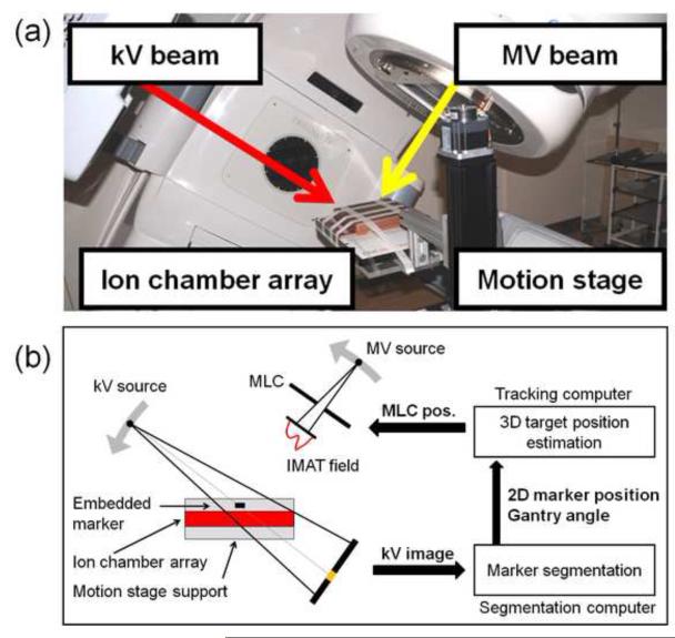
Fig.1 shows the experimental setup for kV image-based DMLC tracking. A motion stage was programmed to reproduce a patient-measured tumor trajectory during IMAT treatment delivery. A Seven29 2D ion chamber array (PTW,Freiburg,Germany) was placed on the motion stage in order to measure the delivered dose distribution. For dose build-up, a 5cm layer of solid water with an embedded cylindrical gold marker (5mm length,1mm diameter) was placed on top of the ion chamber. The treatment was delivered by a Trilogy linear accelerator equipped with a kV On-Board Imager(OBI) system and a 120 leaves Millennium MLC (Varian Medical Systems,Palo Alto,CA).
Fig.1.
(a)Photo and(b) schematic of the dynamic MLC tracking experiments.
The experiments were performed with the same tumor trajectories and IMAT plans as used by Keall et al. in a study of electromagnetic-guided DMLC tracking for IMAT(9). The trajectories were four lung tumor trajectories and four prostate tumor trajectories selected from large abdominal/thoracic(14) and prostate(15) motion databases as representing characteristic motion patterns for these tumor sites. The lung tumor trajectories represented “typical” motion, high-frequency breathing, predominantly left-right motion, and baseline variations(9,11). The prostate trajectories represented continuous drift, persistent excursion, transient excursion, and high-frequency excursions(9-10). The trajectories are shown in Fig.1 of Ref.(9). For each trajectory, a low modulation and a high modulation 6MV RapidArc IMAT plan with a single 358° arc were used(9). The collimator rotation was 90 degrees resulting in MLC leaf motion parallel to the cranio-caudal direction. The plans were originally designed to give 2Gy to 95% of the PTV, but the reduced attenuation in the current phantom compared to the patients resulted in delivered maximum doses of 2.7-3.5Gy. Unlike Ref.(9), the IMAT fields were delivered with modulated dose rate and gantry speed. The low and high modulation prostate plans had 422 monitor units(MU) and 737MU, respectively and were delivered with dose rate modulations of 260-440MU/min and 380-600MU/min, respectively. The lung plans had 342MU delivered at 210-320MU/min (low modulation) and 596MU delivered at 360-600MU/min (high modulation). The treatment delivery time was 75-83 seconds.
The DMLC tracking based on a single kV imager perpendicular to the treatment beam has been described previously(10-11). In short, continuous kV images were acquired at 5Hz with the OBI system during treatment and during a pre-treatment arc spanning 120°. Approximately 500 images were acquired per treatment. The field size was 4cm×6cm and the exposure settings were 90kV,80mA,and 25ms. Each image was captured directly from the imager by an in-house made marker segmentation program using a frame grabber and the research application iTools Capture (Varian Medical Systems)(12). The projected 2D position of the gold marker in the kV image was segmented and sent to a tracking computer. Here, a prototype DMLC tracking program estimated the 3D marker position from the 2D position in the current image and all previous kV images(16), fitted the planned MLC aperture to the estimated 3D target position and sent the new leaf positions to the MLC controller(Fig.1b). The 3D target position estimation was performed every 200ms when a new image was acquired, while the MLC fitting and adjustment took place every 33ms for faster accommodation to changes in gantry angle and planned MLC aperture. For the lung tumor trajectories, a kernel density estimation-based prediction algorithm(17) was applied to account for the tracking system latency of 290ms (image acquisition and transfer(110ms,(12)), marker segmentation(14ms), single-imager 3D marker position estimation(13ms), mean waiting time between new 3D position estimation and next-coming MLC fitting(16ms), MLC fitting(4ms), half of the imaging interval(100ms)(18), and half of the MLC adjustment duration(30ms)(18)).
For each combination of motion trajectory and IMAT plan, the 2D dose distribution to the moving phantom was measured with the ion chamber array with and without DMLC tracking. The dose distributions were compared with a reference dose distribution delivered by the same IMAT plan to the static phantom placed with the central ion chamber in the isocenter. The dose comparison was made using γ-tests with pass criteria of 2mm/2% and 3mm/3% distance-to-agreement. Here, the percentage dose difference was calculated relative to the maximum dose in the static reference experiment and doses below 5% were ignored.
Dosimetric error contributions
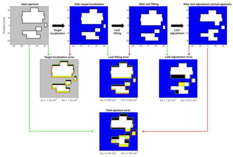
At any time point during the tracking experiments, the ideal MLC aperture was given by the planned MLC aperture shifted to the actual target position in beam’s eye view of the treatment beam. Fig.2 (upper left corner) shows this aperture at a certain instant during a tracking experiment with the high modulation lung plan. If this ideal aperture were formed perfectly during tracking, the resulting target dose distribution would be identical to the static target reference dose distribution except for small discrepancies due to the kV imaging dose(~2cGy) and uncompensated differences in the target depth and off-axis factor in the tracking experiments. However, several errors were introduced in the real-time adaptation of the MLC leaves.
Fig.2.
Top row: Example of MLC aperture formation during dynamic MLC tracking. The ideal MLC aperture(i.e. the planned aperture shifted to the actual target position) is transformed into the actual MLC aperture in the three sequential steps of target localization, leaf fitting, and leaf adjustment. Middle row: Mismatch between ideal/wanted MLC aperture(green) and resulting MLC aperture(red) for each step shown as the resulting under-exposed areas Au(black) and over-exposed areas Ao(yellow). The resulting MLC leaves are shown with blue and black color while the aperture is shown with white and yellow. Bottom: Total Au and Ao for all three steps from ideal to actual MLC aperture.
The upper row in Fig.2 illustrates how the real-time MLC adaptation took place in three sequential steps. First, the target position was estimated. This step resulted in localization errors due to imperfections in the single-imager estimation method, the imaging discreteness and prediction errors (for lung tumors) or the time lag between actual and estimated target position(for prostate). Consequently, the tracking program attempted to shift the planned MLC aperture to a slightly wrong position, which is shown as the second aperture in Fig.2, upper row. Next, the MLC leaves were fitted to this aperture shape, but this step resulted in leaf fitting errors because of the finite leaf width of 5mm(Fig.2,upper row). Finally, the MLC leaves were requested to move to the fitted leaf position, but this step resulted in leaf adjustment errors due to the finite leaf speed. As a result, the actual MLC aperture at this time instance was the aperture shown in the upper right corner of Fig.2.
To analyze the relative importance of the MLC aperture errors(target localization, leaf fitting, leaf adjustment) the under-exposed area Au and the over-exposed area Ao were introduced as a common metric for the MLC aperture mismatch. Au is the area in beam’s eye view of the treatment beam that should have been exposed to radiation, but was shielded by an MLC leaf. Similarly, Ao is the area that should have been shielded by an MLC leaf, but was exposed to radiation. As illustrated with black and yellow color in Fig.2, Au and Ao were calculated for each of the three MLC shaping steps individually (Fig.2,middle row) and for all three steps combined(Fig.2,bottom). The calculation of Au and Ao was performed after the experiments. It was based on the known motion stage trajectory and log files with the real-time estimated target position, the MLC leaf positions before and after leaf fitting, and the actual MLC leaf positions. The log file writing, and thus the Au and Ao calculation, was performed at each MLC leaf position update(30Hz) during all experiments both with and without tracking. The dose-rate weighted average of Au and Ao was calculated for each experiment.
RESULTS
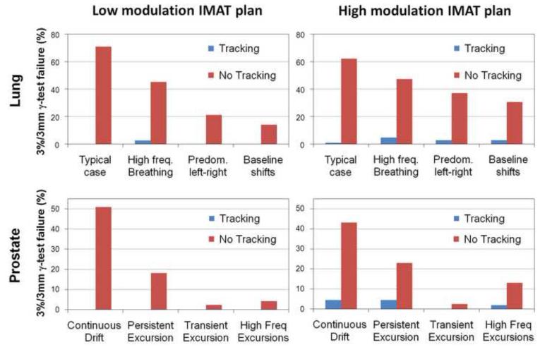
Fig.3 shows the γ-failure rates with and without DMLC tracking using the 3mm/3% pass criteria. DMLC tracking resulted in substantial γ-failure reductions. For the low modulation IMAT plans, the mean 3mm/3% γ-failure rate was 38%(lung) and 19%(prostate) without tracking and 0.7%(lung) and 0%(prostate) with tracking. For the high modulation plans, the residual γ-failure was somewhat larger for tracking, which compared to no tracking, reduced the mean 3mm/3% γ-failure rate from 44% to 2.8%(lung) and from 20% to 2.7%(prostate). Use of the 2mm/2% γ-criteria gave similar trends with mean γ-failure rate reductions from 53%/54% to 5.5%/10%(lung) and from 32%/34% to 0%/4%(prostate) for low/high modulation IMAT plans. During tracking the 2D root-mean-square error in the real-time target position estimation in beam’s eye view of the MV treatment beam had a mean (and maximum) of 0.7mm(1.3mm) for the prostate trajectories and 1.8mm(2.1mm) for the lung tumor trajectories.
Fig.3.
Percentage of points failing the 3mm/3% γ-test with and without tracking for the four lung tumor trajectories(top) and the four prostate trajectories(bottom). Left: low modulation IMAT plans. Right: high modulation IMAT plans.
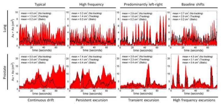
The residual γ-failures with tracking resulted from errors in the three MLC shaping steps of target localization, leaf fitting, and leaf adjustment. In Fig.4, the total MLC shaping error caused by all three steps is quantified by the sum Au+Ao, which is shown as a function of treatment delivery time for all experiments with the high modulation IMAT plans(both tracking and non-tracking). The dose-rate weighted average of Au+Ao is indicated for each experiment in the figure. The low modulation plans gave similar results and are not presented. In the static target reference experiments, only leaf adjustment contributed to Au+Ao, as the target localization was perfect by definition and no leaf fitting was performed during the experiments. It resulted in very small values of Au+Ao as seen by the gray areas in Fig.4. In the target motion experiments without tracking, the lack of target localization resulted in large position estimation errors with large contributions to Au+Ao(Fig.4,red). For these experiments, the time evolvement of Au+Ao directly reflected the target motion in beam’s eye view of the treatment beam. The black curves in Fig.4 show Au+Ao with DMLC tracking. Although tracking resulted in large reductions in Au+Ao the residual under- and over-exposure was still substantially higher than in the static reference experiments.
Fig.4.
Sum of total under-exposed and over-exposed areas, Au+Ao, as a function of treatment delivery time for static target(gray), moving target without tracking(red), and moving target with tracking(black curve). The graphs show the results for the high modulation IMAT plans for lung(top) and prostate(bottom). The dose-rate weighted average of Au+Ao is specified in each graph.
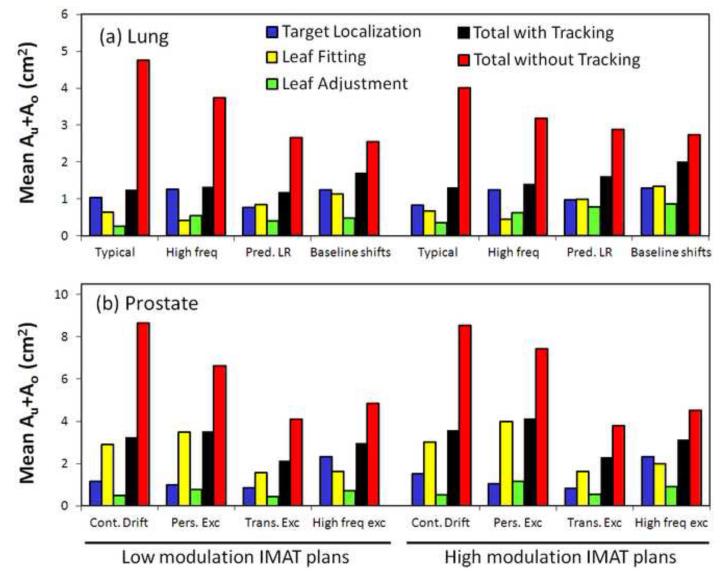
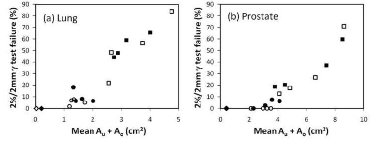
In order to identify the causes of the MLC aperture errors, Fig.5 shows the three individual contributions to Au+Ao as well as the total Au+Ao for each tracking experiment. The figure shows the dose-rate weighted average of Au+Ao. For comparison, the figure also presents the total Au+Ao without tracking. In the tracking experiments, the total Au+Ao (Fig.5,black) was generally smaller than the sum of the individual contributions(blue,yellow,green) as errors made in one MLC shaping step was partly compensated by errors in another step. In many cases, the error in a single MLC shaping step was dominant and almost of same magnitude as the total Au+Ao. For lung tumor trajectories, the target localization error(blue) was the dominating contributor except for the trajectories with predominant left-right motion and baseline shifts. These trajectories involved substantial target motion perpendicular to the MLC leaves, resulting in leaf fitting errors (yellow) of magnitudes similar to the target localization errors(Fig.5). For prostate trajectories, leaf fitting was the main contributor to Au+Ao except for the high-frequency excursion trajectory, where the time lag between target motion and MLC adaptation led to large target localization errors after abrupt changes in the target position(see Fig.4,lower right). The impact of plan complexity can be seen by comparing Au+Ao for the high modulation IMAT plans(Fig.5,right) with the low modulation plans(left). With tracking, the mean of the total Au+Ao was 17% higher for the high modulation plans mainly because of a large 47% increase in the individual contribution from leaf adjustment. Without tracking, no effect of plan complexity was observed. As seen by the scatter plots in Fig.6, the total Au+Ao was a good indicator for the γ-failure rates and thus the dosimetric quality of the treatment delivery.
Fig.5.
Dose-rate weighted average of Au+Ao. Individual contributions with DMLC tracking from target localization(blue), leaf fitting(yellow), and leaf adjustment(green) as well as the combined result of all three steps with DMLC tracking(black) and without tracking(red).
Fig.6.
Scatter plot showing the 2%/2mm γ-failure rate versus the dose-rate weighted average of Au+Ao for the static reference experiments(diamonds) and the moving target experiments with tracking(circles) and without tracking(squares). Open symbols: Low modulation IMAT plans. Closed symbols: High modulation plans.
DISCUSSION
Image-based DMLC tracking during IMAT treatment delivery was demonstrated for the first time, resulting in large improvements in the dose distribution to a moving target. The improvements were similar to those observed for electromagnetic DMLC tracking with the same tumor motion trajectories and IMAT plans(9).The under-exposed and over-exposed areas, Au and Ao were introduced as a common metric for the errors in the MLC adaptation to the moving target. This framework allowed direct comparison of the individual error contributions in the chain of events that lead to the final MLC aperture during DMLC tracking. For lung tumor motion, target localization was the dominating error contributor, except in cases with substantial motion perpendicular to the MLC leaves, where leaf fitting gave equally large contributions. The contribution from leaf adjustment was smaller, but increased more than the other contributions with plan complexity. These findings suggest that better target localization, e.g. by reduced tracking latency or better prediction would be the best way to improve the DMLC tracking. For prostate motion, leaf fitting was the dominating error contributor, suggesting that thinner MLC leaves or more robust planning with DMLC tracking in mind would be the best way to improve the tracking.
While Au and Ao from the three error contributions could be reduced by better target localization, thinner leaves, and faster leaves, respectively, another strategy would be to mitigate the impact of erroneous exposure by intra-treatment detection and compensation. Errors from leaf fitting and leaf adjustment can be detected in real time during the tracking treatment delivery. This allows correction strategies, such as instant beam holds or compensation of dose deficits later on in the treatment. For position estimation errors, the part caused by prediction could be detected in near real time, allowing for dose deficit compensation strategies later on in the treatment delivery. Intra-treatment dose deficit compensation would be simplest for fixed gantry beams, where the target dose distribution is approximately proportional to the accumulated 2D fluence that the beam delivers to the moving target. For arc treatments, such dose deficit compensation would be substantially more complicated since a full 3D dose calculation would be needed in order to compensate for dose deficits from one gantry angle by fluence modifications at another gantry angle.
In this study, the total Au+Ao averaged over a treatment was used as an indicator for the dosimetric error. Although Au+Ao does not account for the MLC aperture errors being random with a tendency to cancel out or systematic with a tendency to be additive, it turned out to be a good predictor for the observed γ-failure rates(Fig.6). The developed framework where the mutual target and MLC positions are always known during treatment delivery lays the foundation for accurate calculation of the accumulated target dose distribution during DMLC tracking.
Gimbal tracking(19) and couch tracking(20) are alternatives to DMLC tracking that do not involve leaf fitting or leaf adjustment in the beam-target realignment. In the current framework this leaves target localization as the only contributor to MLC aperture errors, which may suggest large improvements over DMLC tracking(compare blue and black columns in Fig.5). However, contributions from the response time of the beam-target alignment systems (gimbal tilt or couch shift) would need to be added. Furthermore, even gimbal and couch tracking(and non-tracking treatments) will normally involve leaf fitting errors introduced during treatment planning when an optimal fluence is approximated by a deliverable fluence in the leaf sequencing step. DMLC tracking has the advantages of wider availability, the ability to account for target rotation and deformation, and avoidance of moving the patient.
CONCLUSION
Image-based tracking for IMAT was demonstrated for the first time. The tracking greatly improved the dose distributions to moving targets.
Summary.
Continuous kV images were acquired during IMAT treatment of a moving phantom and used for dynamic MLC tracking, i.e. repeated realignment of the MLC aperture with the phantom position. The tracking substantially improved the dose distributions to moving targets. Errors in the MLC realignment caused by real-time target localization, leaf fitting and leaf adjustment were analyzed in detail.
ACKNOWLEDGEMENTS
The authors gratefully thank Drs Patrick Kupelian and Katja Langen, MD Anderson Cancer Center Orlando, for the prostate trajectories, Drs Yelin Suh and Sonja Dieterich, Stanford University, for the thoracic/abdominal tumor trajectories, and Xinhui Yang, Daniel Morf, and Stefan Scheib,Varian Medical Systems, for the iTools Capture software. This work was supported by US NIH/NCI grant R01 CA93626, Varian Medical Systems, The Danish Cancer Society, CIRRO - The Lundbeck Foundation Center for Interventional Research in Radiation Oncology. We gratefully thank Julie Baz, University of Sydney, for reviewing this manuscript.
Footnotes
Publisher's Disclaimer: This is a PDF file of an unedited manuscript that has been accepted for publication. As a service to our customers we are providing this early version of the manuscript. The manuscript will undergo copyediting, typesetting, and review of the resulting proof before it is published in its final citable form. Please note that during the production process errors may be discovered which could affect the content, and all legal disclaimers that apply to the journal pertain.
Conflicts of interest: Drs Poulsen, Cho and Keall receive royalties from a patent related to this work.
REFERENCES
- 1.Yu CX. Intensity-modulated arc therapy with dynamic multileaf collimation: an alternative to tomotherapy. Phys Med Biol. 1995;40:1435–1449. doi: 10.1088/0031-9155/40/9/004. [DOI] [PubMed] [Google Scholar]
- 2.Otto K. Volumetric modulated arc therapy: IMRT in a single gantry arc. Med Phys. 2008;35:310–317. doi: 10.1118/1.2818738. [DOI] [PubMed] [Google Scholar]
- 3.Wang C, Luan S, Tang G, et al. Arc-modulated radiation therapy (AMRT): a single-arc form of intensity-modulated arc therapy. Phys Med Biol. 2008;53:6291–6303. doi: 10.1088/0031-9155/53/22/002. [DOI] [PubMed] [Google Scholar]
- 4.Keall PJ, Kini VR, Vedam SS, et al. Motion adaptive x-ray therapy: a feasibility study. Phys Med Biol. 2001;46:1–10. doi: 10.1088/0031-9155/46/1/301. [DOI] [PubMed] [Google Scholar]
- 5.Sawant A, Venkat R, Srivastava V, et al. Management of three-dimensional intrafraction motion through real-time DMLC tracking. Med Phys. 2008;35:2050–2061. doi: 10.1118/1.2905355. [DOI] [PMC free article] [PubMed] [Google Scholar]
- 6.Liu Y, Shi C, Lin B, et al. Delivery of four-dimensional radiotherapy with TrackBeam for moving target using an AccuKnife dual-layer MLC: dynamic phantoms study. J Appl Clin Med Phys. 2009;10:2926. doi: 10.1120/jacmp.v10i2.2926. [DOI] [PMC free article] [PubMed] [Google Scholar]
- 7.Krauss A, Nill S, Tacke M, et al. Electromagnetic real-time tumor position monitoring and dynamic multileaf collimator tracking using a Siemens 160MLC: geometric and dosimetric accuracy of an integrated system. Int J Radiat Oncol Biol Phys. 2011;79:579–587. doi: 10.1016/j.ijrobp.2010.03.043. [DOI] [PubMed] [Google Scholar]
- 8.Zimmerman J, Korreman S, Persson G, et al. DMLC motion tracking of moving targets for intensity modulated arc therapy treatment: a feasibility study. ActaOncol. 2009;48:245–250. doi: 10.1080/02841860802266722. [DOI] [PubMed] [Google Scholar]
- 9.Keall PJ, Sawant A, Cho B, et al. Electromagnetic-guided dynamic multileaf collimator tracking enables motion management for intensity-modulated arc therapy. Int J Radiat Oncol Biol Phys. 2011;79:312–320. doi: 10.1016/j.ijrobp.2010.03.011. [DOI] [PMC free article] [PubMed] [Google Scholar]
- 10.Poulsen PR, Cho B, Sawant A, et al. Implementation of a new method for dynamic multileaf collimator tracking of prostate motion in arc radiotherapy using a single kV imager. Int J Radiat Oncol BiolPhys. 2010;76:914–923. doi: 10.1016/j.ijrobp.2009.06.073. [DOI] [PubMed] [Google Scholar]
- 11.Poulsen PR, Cho B, Ruan D, et al. Dynamic multileaf collimator tracking of respiratory target motion based on a single kilovoltage imager during arc radiotherapy. Int J Radiat Oncol Biol Phys. 2010;77:600–607. doi: 10.1016/j.ijrobp.2009.08.030. [DOI] [PubMed] [Google Scholar]
- 12.Fledelius W, Keall PJ, Cho B, et al. Tracking latency in image-based dynamic MLC tracking with direct image access. ActaOncol. 2011;50:952–959. doi: 10.3109/0284186X.2011.581693. [DOI] [PubMed] [Google Scholar]
- 13.Poulsen PR, Cho B, Sawant A, et al. Dynamic MLC tracking of moving targets with a single kV imager for 3D conformal and IMRT treatments. ActaOncol. 2010;49:1092–1100. doi: 10.3109/0284186X.2010.498438. [DOI] [PubMed] [Google Scholar]
- 14.Suh Y, Dieterich S, Cho B, et al. An analysis of thoracic and abdominal tumour motion for stereotactic body radiotherapy patients. Phys Med Biol. 2008;53:3623–3640. doi: 10.1088/0031-9155/53/13/016. [DOI] [PubMed] [Google Scholar]
- 15.Langen KM, Willoughby TR, Meeks SL, et al. Observations on real-time prostate gland motion using electromagnetic tracking. Int J Radiat Oncol Biol Phys. 2008;71:1084–1090. doi: 10.1016/j.ijrobp.2007.11.054. [DOI] [PubMed] [Google Scholar]
- 16.Poulsen PR, Cho B, Keall PJ. Real-time prostate trajectory estimation with a single imager in arc radiotherapy: a simulation study. Phys Med Biol. 2009;54:4019–4035. doi: 10.1088/0031-9155/54/13/005. [DOI] [PubMed] [Google Scholar]
- 17.Ruan D. Kernel density estimation-based real-time prediction for respiratory motion. Phys Med Biol. 2010;55:1311–1326. doi: 10.1088/0031-9155/55/5/004. [DOI] [PubMed] [Google Scholar]
- 18.Poulsen PR, Cho B, Sawant A, et al. Detailed analysis of latencies in image-based dynamic MLC tracking. Med Phys. 2010;37:4998–5005. doi: 10.1118/1.3480504. [DOI] [PMC free article] [PubMed] [Google Scholar]
- 19.Depuydt T, Verellen D, Haas O, et al. Geometric accuracy of a novel gimbals based radiation therapy tumor tracking system. RadiotherOncol. 2011;98:365–372. doi: 10.1016/j.radonc.2011.01.015. [DOI] [PubMed] [Google Scholar]
- 20.D’Souza WD, Naqvi SA, Yu CX. Real-time intra-fraction-motion tracking using the treatment couch: a feasibility study. Phys Med Biol. 2005;50:4021–4033. doi: 10.1088/0031-9155/50/17/007. [DOI] [PubMed] [Google Scholar]


