

Abstract
The aim of this investigation was to achieve the first step towards a comprehensive model of the lymphatic system. A numerical model has been constructed of a lymphatic vessel, consisting of a short series chain of contractile segments (lymphangions) and inter-segmental valves. The changing diameter of a segment governs the difference between the flows through inlet and outlet valves, and is itself governed by a balance between transmural pressure, and passive and active wall properties. The compliance of segments is maximal at intermediate diameters, and decreases when the segments are subject to greatly positive or negative transmural pressure. Fluid flow is the result of time-varying active contraction causing diameter to reduce, and is limited by segmental viscous and valvular resistance. The valves effect a smooth transition from low forward-flow resistance to high backflow resistance. Contraction occurs sequentially in successive lymphangions in the forward-flow direction. The behaviour of chains of one to five lymphangions was investigated by means of pump function curves, with variation of valve opening parameters, maximum contractility, lymphangion size gradation, number of lymphangions, and phase delay between adjacent lymphangion contractions. The model was reasonably robust numerically, with mean flow-rate generally reducing as adverse pressure was increased. Sequential contraction was found to be much more efficient than synchronised contraction. At the highest adverse pressures, pumping failed by one of two mechanisms, depending on parameter settings: either mean leakback flow exceeded forward pumping, or contraction failed to open the lymphangion outlet valve. Maximum pressure and maximum flow-rate were both sensitive to the contractile state; maximum pressure was also determined by the number of lymphangions in series. Maximum flow-rate was highly sensitive to the transmural pressure experienced by the most upstream lymphangions, suggesting that many feeding lymphatics would be needed to supply one downstream lymphangion chain pumping at optimal transmural pressure.
Keywords: lymphatic system, lymphatic vessel, lymph transport, mathematical model
1 Introduction
The lymphatic system plays a critical role in maintaining health, by continuously returning fluid and circulating protein from the interstitial space to the blood. Conversely, the lymphatic system is intimately involved in the spread of disease: once tumours metastasise, malignant cancer cells travel through the lymphatic system to establish new sites of tumour formation. Lymphatic system disruption causes swelling or œdema, and usually leads to immune system malfunction.
Thus proper function of the lymphatic system is crucial to health. Nevertheless, this ‘third circulation’ has received little attention from bioengineers relative to the arterial and venous systems. From the engineer’s point of view, the lymphatic system is uniquely interesting, because of the distributed and variegated nature of the pumping which causes lymph transport. All lymph passes through at least one node, which themselves present relatively high resistance [1]. Interstitial tissue pressure ranges broadly around atmospheric [2], i.e. roughly the same as the pressure at the thoracic outflow to the veins. Upstream pressure thus cannot propel the lymph produced in most organs. The exit point, near the heart, is above the majority of body tissues in upright posture, so most pumping is ‘up-hill’. Pumping depends on both extrinsic and intrinsic mechanisms. Extrinsic mechanisms include compression of valved lymphatics during external tissue deformation by skeletal muscle contraction, respiration, active or passive limb motion, blood vessel pulsation, etc. However, the greater part of lymph flow is driven by intrinsic contraction of lymphangions, the vessel segments between each pair of valves.
Reddy [3–4] developed a network model of lymphatic flow in the thoracic duct and some seven generations of branches upstream. Contraction in response to strain was modelled, but a single frequency and uniform phase everywhere was assumed. The model predicted flow rates typical of normal lymphatic function, but did not deal with disease states involving inadequate lymphatic clearance. It neglected the non-contractile initial lymphatics, and the small lymphangions where much of the important pumping happens. More recently, models of short chains of contracting lymphangions have been developed by Quick et al. [5–6], Macdonald et al. [7] and Yao et al. [8]. However in each case the valves were simplified to the most basic level, by implicitly or explicitly setting negative flow to zero. At best the valves offered low or zero resistance to forward flow, and infinite resistance to retrograde flow, and switched instantaneously between these states as the transvalvular pressure drop passed through zero. In some cases, the cancellation of negative flow occurred as a final step in the computation of a time-step, and was not apparently reconciled with the rest of the equations.
We here describe a model in which the valves are treated more realistically as devices with a finite resistance to forward flow, and a much higher but less than infinite resistance to backflow. The transition between these states occurs over a finite range of pressure difference across the valve. The vessel segments between the valves are given a realistic constitutive relation which allows for both passive stiffening with increasing distension and collapse when transmural pressure is negative. The model is used to explore the situation of both initial collecting lymphatics, where transmural pressure is zero [9], and lymphangions downstream where lymph pressure exceeds interstitial pressure. Pump function curves are derived for varying numbers of lymphangions and differing degrees of strength of contraction. The model has a number of further abilities, e.g. to simulate dysfunction, which are not exercised here.
2 Methods
2.1 Model equations
A number of contractile vessel segments are linked by valves to form a series chain which begins at a reservoir of constant pressure pa and ends at one of (higher) pressure pb; see Figure 1. The chain is subjected externally to the uniform pressure pe. A general lymphangion i is characterised by the time-dependent variables of diameter Di, pressures pi1 and pi2 at the upstream and downstream ends, and flow-rates Qi in and Qi+1 out. These flow-rates are thus also those through the corresponding valves with resistance RVi and RVi+1.
Figure 1.
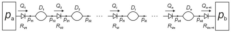
Schematic of the lymphangion-chain model. Non-return valves, characterized by through flow-rate Q and flow resistance RV, alternate with contractile vessel segments characterized by their diameter D. Pressure p is defined at each of the sites joining these elements (effectively, the upstream and downstream end of each segment).
Each vessel segment is described by conservation of fluid mass and of fluid momentum
(t = time, D = diameter, L = length, ρ = density, μ = viscosity). We make the quasi-steady assumption of fully developed Poiseuille flow at all times, justified by the extremely small Reynolds numbers (always less than 2) of flow in the small lymphatic vessels being considered here (< 0.4 mm diameter). The equations are completed with a vessel wall constitutive relation including both passive and periodic contractile components
(ptm = transmural pressure, f = frequency) where contraction strength M = 0 for t < t0i (M has the dimensions of smooth muscle force per unit length, or tension). The parameters pe, L, M and f could in principle be different for each lymphangion, but here are taken as constant over the whole chain. The first term on the right of the constitutive equation describes the passive properties of wall-stiffening with strain at positive transmural pressure [10] by the exponential function, and progressively diminishing vessel compliance at negative transmural pressure by the cubic function [11]. The way in which the term is controlled by the two parameters Pdi and Ddi is shown in Figure 2. The second term on the right of the equation simply relates (actively varying) hoop tension to distending pressure; it can be regarded as an expression of the so-called ‘law of Laplace’.
Figure 2.

The effect of parameters Pd and Dd on the passive part of the constitutive relation relating diameter Di to transmural pressure ptm. Upper panel: Pd = 100 dyn cm−2, Dd = 0.015 (dashed), 0.020 (solid) and 0.015 (dot-dashed) cm. Lower panel: Dd = 0.02 cm, Pd = 20 (dotted), 50 (dashed), 100 (solid) and 150 (dot-dashed) dyn cm−2.
Each valve was modelled as a flow resistance varying with the applied pressure difference Δp according to two sigmoidal functions. The first describes normal opening and transition from high resistance RVmax to low resistance RVmin when the pressure drop across it exceeds a small positive value popen. The second describes valve failure (prolapse) at the (large) adverse pressure difference pfail,
where Δp = p12 − p21 if we consider the valve downstream of the first lymphangion. Again, the parameters RVmin, RVmax, sopen, sfail, popen and pfail could in principle take different values at each lymphangion, but were here constant across the chain. The behaviour of the normal valve-opening part of the function is shown in Figure 3.
Figure 3.

The variation of valve resistance RV with pressure difference across the valve Δp, showing how the constants sopen and Popen control the opening function of the valves. Upper panel: sopen = 0.04 cm2 dyn−1, popen = −20 (dashed), −70 (solid) and −120 (dot-dash) dyn cm−2. Lower panel: sopen = 0.02 (dashed), 0.04(solid) and 0.08 (dot-dash) cm2 dyn−1, popen = −70 dyn cm−2.
2.2 Method of solution
The unknowns were Di, pi1, and pi2, for i = 1 … n, and Qi, for i = 1 … n +1, where n is the number of lymphangions. Noting that p02 = pa, and p(n+1)1 = pb, each valve-resistance equation, cast as f(p(i−1)2 − pi1) = Qi, enabled substitution of the local flow-rate Qi. Then the algebraic-differential system for all the diameters and pressures was solved as a nonlinear minimum-finding problem of dimension 2n nested inside an ordinary differential equation (o.d.e.) problem of dimension n which was given to a standard o.d.e. solver.
Simulations for up to five lymphangions are presented here. The lymphangions were activated sequentially after the start of the simulation, so that each contracted after the one upstream according to the start time t0i. Once contraction started, the active tension varied continuously in sinusoidal fashion, with period 2 s. In vivo, upstream and downstream transmission of contraction signals have both been observed, as have unsynchronised contractions, but downstream transmission is more usual [12–13]. Therefore usually t0i = i/2 s, so that each lymphangion lagged that upstream by 90°, but other delays were also investigated. The equations were run for as many periods as it took to obtain fully periodic solutions with identical mean flow-rates over a cycle through all valves. For three lymphangions, 50 s of simulation time normally sufficed; for four, 80 s was found preferable, but under some circumstances this many periods were needed to obtain flow-rate agreement in even the single-lymphangion model. Coded in Matlab running interpreted rather than compiled, solution of the equations for five lymphangions over 80 s of simulation under favourable conditions took 16 minutes on a Pentium 4 cpu running at 3.8 GHz. The model has been run with up to eight lymphangions, but no upper limit for n has been found.
Parameters were set to values representative of a typical small lymphatic vessel, but no attempt was made to emulate a particular set of physiological data. The majority of parameters, once set, were left as constants; see Table 1. The effect of a change in the opening properties of the valves was examined by varying sopen and popen together. The effect of increasing the maximum valve resistance was also examined, and concomitant changes in sopen and popen were made. These combinations together defined three valve types, herein referred to as V3, V4 and V5. The passive relation between transmural pressure and diameter for a lymphangion was determined by the parameters Pdi and Ddi. On the basis that average transmural pressure must increase along a series lymphangion chain, and that lymphangions in vivo will adapt to this, Pdi and Ddi were usually given incrementally differing values along the chain; the effect of equal Ddi everywhere was also examined. The pressure pa of the upstream reservoir was either equal to pe, or 87.5 or 175 dyn cm−2 greater.
Table 1.
Parameter definitions and settings, including variations.
| valve failure pressure | pfail | −1.8 × 10⁴ | dyn cm−2 |
| valve failure slope | sfail | 4.9 × 10⁻² | cm2 dyn−1 |
| min. valve resistance | RVmin | 600 | dyn cm−2/ml s−1 |
| max. valve resistance | RVmax | 1.2 × 10⁷ (V3, V4) 4.8 × 10⁷ (V5) |
dyn cm−2/ml s−1 |
| valve opening slope | sopen | 0.04 (V3) 0.05 (V4) 0.20 (V5) |
cm2 dyn−1 |
| valve opening pressure | popen | −70 (V3) −30 (V4) −15 (V5) |
dyn cm−2 |
| fluid viscosity | μ | 1 | cP |
| lymphangion length | L | 0.3 | cm |
| constitutive-relation const. | Pdi (for i = 1,4) | 50, 75, 100, 125 | dyn cm−2 |
| constitutive-relation const. | Ddi (for i = 1,4) | 0.025, 0.022, 0.019, 0.016 or all 0.021 or 0.029, 0.039, 0.049 | cm |
| max. active tension | M | 3.6 or 5.4 | dyn cm−1 |
| contraction frequency | f | 0.5 | Hz |
| inter-lymphangion phase | via t0i | usually 90° also from −45° to 180° | |
| external pressure | pe | 2100 | dyn cm−2 |
| inlet pressure | pa | 2100 or 2087.5 or 2175 | dyn cm−2 |
| outlet pressure | pb | ≥ pa | dyn cm−2 |
| adverse pressure overcome by chain | ΔP | = pb − pa | dyn cm−2 |
| pressure difference across valve i | Δp | = p(i−1)2 − pi1 | dyn cm−2 |
Pump function curves were generated by running simulations as above with many different values of downstream pressure pb, and plotting the resulting values of cycle-mean flow-rate Q̄ against the opposing pressure difference ΔP = pb − pa. Continuous curves were constructed with the aid of spline fits to the data points.
3 Results
3.1 Waveforms
Analysis of chains of lymphangions in series showed cyclic, non-sinusoidal variations in flow, with each lymphangion reaching peak flow-rate after the one upstream. This behaviour is first illustrated (Figure 4) with four lymphangions in series pumping against a downstream pressure high enough to cause zero net flow-rate (in fact a small negative Q̄). The figure shows two periods (4 s) after start-up transients have decayed. In this case all lymphangions remain continuously distended, that is, their diameters D1 to D4 (Fig. 4, second panel) are always greater than the respective values Dd1 to Dd4. Because the vessels are distended, the pressure drop within each lymphangion due to flow resistance is small relative to the adverse pressures borne by the valves under this pumping circumstance; thus the eight pressures (Fig. 4, top panel) form four closely similar pairs of waveforms, where each pair consists of the pressure at the upstream and downstream end of the vessel segment between two valves. Each waveform pair is approximately sinusoidal, and roughly in phase (slightly leading) the corresponding waveform of lymphangion contractile state (dashed curves, middle panel). There is a regular staircase progression of mean pressures climbing toward the target of pb. Instantaneous flow-rate through each valve (bottom panel) peaks at roughly the same value, and forward flow has roughly similar duration for each. The order of peaks is misleading, in that the Q5 peak occurs between those for Q1 and Q2. In fact this is the Q5 peak for the previous downstream-propagating wave of contraction; each Q5 peak should be related to the preceding Q4 peak. The time between the Q1 peak and the Q2 peak is considerably greater than those between the Q2, Q3 and Q4 peaks; similarly, the time between the Q4 peak and the following Q5 peak is greater.
Figure 4.

Cyclic pumping by a chain of four lymphangions, against a pressure difference (600 dyn cm−2 or 0.612 cm H2O) sufficient to produce a small negative mean flow-rate (−0.01 ml/hr). Top panel: the waveform of active tension in each lymphangion. Second panel: the four time-varying lymphangion diameters. Third panel: the eight different time-varying pressures—also shown as horizontal black lines are the pressures pa and pb. Bottom panel: the flow-rate through each of the five valves. Parameters for this run: M = 3.6 dyn cm−1 (all lymphangions), pa = 2275, pb = 2875 dyn cm−2; Dd1 = 0.025, Dd2 = 0.022, Dd3 = 0.019, Dd4 = 0.016 cm; Pd1 = 50, Pd2 = 75, Pd3 = 100, Pd4 = 125 dyn cm−2; sopen = 0.04 cm2 dyn−1, popen = −70 dyn cm−2.
The nature of the pumping changes considerably when the lymphangion chain is faced with only a small adverse pressure difference between reservoirs, and the cycle-mean flow-rate is close to that maximum value for normal pump function which occurs when ΔP = 0. Figure 5 shows the same set of waveforms as Fig. 4, but now the downstream pressure has been reduced from 2875 to 2375 dyn cm−2; all other parameters stay the same. The diameters of all four lymphangions are now lower, and vary more over the cycle. Consequently, all four lymphangions now visit both ‘collapsed’ (Di < Ddi)1 and distended states during a cycle of pumping. The previous fully regular pattern of building pressures is now interrupted, in particular by the waveform for the pressure upstream of the final valve, which is effectively capped at values that barely exceed pb. In contrast, the pressures at intermediate locations along the chain reach peaks considerably greater than pb. The waveforms are now less sinusoidal. Because the forward flow-rates are now greater, and the lymphangion diameters less, the pressure drop during forward flow within segments between valves is now apparent. The peak flow-rates through valves now vary greatly, and to compensate, given that mean flow is the same for each lymphangion, the duration of forward flow also varies, being greatest where the peak is least. Because of differences in the flow-rate waveform shape from one valve to the next, only approximate observations can be made about the timing, but the previous relatively long pause between the Q4 and Q5 peaks has reduced; similarly, the Q2 peak is no longer so delayed relative to Q1. There is still leakage through the forward flow. alves when they are subjected to adverse pressure, but it is no longer as significant relative to the valves when they are subjected to adverse pressure, but it is no longer as significant relative to the forward flow.
Figure 5.

Pumping by the same lymphangion chain as in Fig. 4, but now against a pressure difference of 100 dyn cm−2 (0.102 cm H2O); the mean flow-rate becomes 0.182 ml/hr. All other parameters as for Fig. 4.
3.2 Pump function
Many ΔP/Q̄ combinations for the chain were investigated, allowing the assembly of pump function curves, which exhibit complex parameter-dependent variations in shape. The curve for the 4-lymphangion chain from Figs. 4 and 5 (Figure 6a, diamond symbols) has a shape indicating neither flow-source nor pressure-source behaviour, but rather a gradually varying finite source resistance. As a first exploration of pump parameter changes, the valve resistance was altered so that the resistance to backflow was increased (V4 in Fig. 6). This change also resulted in an increase of valve resistance when trans-valvular Δp was small and positive. The V3 valves in fact resulted in slightly higher Q̄ at all pressure differences from no flow to no adverse pressure. The difference is greatest at high Q̄, where valve resistance to forward flow is most significant. Both pump function curves begin at ΔP = 0 with all lymphangions ranging between distended and collapsed states. As ΔP increases and Q̄ decreases, there is a similar progression along each curve whereby first the intermediate lymphangions become continuously distended, then so do the outer ones, with the downstream lymphangion the last to reach this state.
Figure 6.

(a) Pump function, i.e. the relation between mean flow-rate Q̄ and overall adverse pressure difference ΔP = pb − pa, for the 4-lymphangion model, with pae = 175 dyn cm−2, M = 3.6 dyn cm−1, and two different sets of valve-opening parameters. Apart from variation of pb, all parameters are otherwise as for Figs. 4 and 5. The 4-letter code attached to individual data points indicates which of lymphangions 1 to 4 were continuously distended [D] or visited both [b] collapsed and distended states during a cycle of pumping. (b) The valve resistance as a function of pressure difference for each valve-parameter set.
3.2.1 Effect of valve characteristics
As pb continues to increase, the cyclic contractions gradually fail to produce forward pumping. Two different mechanisms interact: leakage and overload. Initially, the pump function curves continue into the region Q̄ < 0 without dramatic change, as was evident in Fig. 6a; a small negative Q̄ is the net result of backflow by leakage over most of the cycle and transient forward flow when a lymphangion pumps. The limit was explored further in a 1-lymphangion model (one contractile segment between two valves). It was found that eventually the pressure pb downstream of the outflow valve exceeds the maximum pressure generated in the lymphangion by active contraction. At that point, forward outflow becomes impossible, and in fact slow backflow occurs (through both closed valves) during the entire cycle. The main result of contraction is variation of the pressure in the lymphangion (in synchrony with the active contraction time-course); the inflow and outflow rates vary somewhat with this pressure, but remain continuously negative. Figure 7 illustrates the effect on the pump function curve. To examine further the effect of valve characteristics, the V5 set of valve parameters was defined as shown in Fig. 7a, incorporating a sharper opening/closing function and a higher maximum resistance to backflow. With valves having this characteristic, the pump was slightly more powerful in terms of both maximum Q̄, thanks to the reduction in leakage, and maximum Δp for forward flow. With only a single contracting segment, the maximum ΔP for forward flow is less than 200 dyn cm−2, much lower than that for multiple lymphangions in Fig. 6. The upturn of the curves in the region Q̄ < 0 is where the valves experience a continuously adverse pressure difference and never open. Ultimately the pump becomes a conduit with a resistance to backflow of approximately 2RVmax, since both valves are involved, as indicated by the dotted lines in Fig. 7b.
Figure 7.

(a) For the purposes of investigating regurgitation, a further valve characteristic, V5, was defined. (b) Pump function curves for the single-lymphangion model with these three valve characteristics, at M = 3.6 dyn cm−1. See text for explanation of the dotted lines.
3.2.2 Effect of number of lymphangions
The maximum ΔP for forward flow increases with the number of lymphangions, as shown by the pump function curves in Figure 8 for 3-, 4- and 5-lymphangion chains. The result of adding a lymphangion to or removing one from the 4-lymphangion chain is strongly parameter-dependent. One might predict that the longer chain would produce both higher values of Q̄ at equivalent values of ΔP, and higher values of ΔP for a given Q̄. In fact, under the conditions of Fig. 8a, where each chain included progressively decreasing Dd-values, while the longer chains could overcome higher adverse pressures at low flow-rates, the shorter chains generated higher flow-rates when facing low values of ΔP. The 3-lymphangion chain completed the transition to pumping with all segments continuously distended somewhat earlier than either of the longer chains, whether compared in terms of equivalent ΔP or equivalent Q̄.
Figure 8.

Comparison of the pump function curves for chains of 3 (blue curve, circle symbols), 4 (magenta curve, diamond symbols) and 5 (red curve, star symbols) lymphangions with V3 valves, at pae = 175 dyn cm−2 and M = 3.6 dyn cm−1. The data for 4 lymphangions in the upper panel are as shown in Fig. 6a (diamond symbols). Parameters as for Fig. 4 except as noted in the legend. (a) With Dd reducing downstream. (b) With constant Dd. A single data-point for a corresponding 8-lymphangion model is also shown. Dotted lines indicate where the chain configuration (C, D, b) changes.
However, a different scenario results when all lymphangions have the same value of Dd. All three chains now perform similarly at high Q̄ and low ΔP (Figure 8b). It is also notable how much sharper the ‘knee’ of the curve is in this circumstance, i.e. the pump now changes quite markedly from an approximately constant-pressure characteristic to one approximating constant flow-rate. As before, intermediate lymphangions are the first to become permanently distended as ΔP increases, and there is now a clear pattern to the order in which lymphangions attain this state as Q̄ decreases. However here, in contrast to what occurred in Fig. 8a, the first lymphangion is the last to reach permanent distension. At ΔP = 0, the downstream lymphangion in the 5-lymphangion chain pumps in the permanently collapsed state.
3.2.3 Effect of transmural pressure
All results shown so far have been for the situation where even the first lymphangion is working at a distending pressure that on average exceeds the external pressure. In vivo, some lymphangions, such as those contractile segments adjacent to the non-contractile initial collecting lymphatics, or those in the vicinity of locally increased interstitial tissue pressure, operate in an environment where the internal and external pressures are nearly equal. This poses special challenges. Figure 9 shows pump function curves for the 3-lymphangion chain when pa = pe. Two different values of the peak contractile state parameter M are shown. Over the whole range from ΔP = 0 to Q̄ = 0, the pump is more powerful when the contractile state is raised (M = 5.4 dyn cm−1). However, with pe now as high as pa, the lymphangions are pumping in a different state. At high Q̄, all remain continuously collapsed. Even at the highest downstream pressure, the first lymphangion must still operate in this regime.
Figure 9.

Comparison of two values of M, the peak contractile state, for the 3-lymphangion chain with V3 valves when pa = pe, i.e. pa = 2100 dyn cm−2. Dotted lines indicate where the chain configuration (C, D, b) changes. All other parameters unchanged from those for three lymphangions in Fig. 8a.
This has consequences for the magnitude of Q̄ that can be generated. Figure 10 compares the pump function curves of the 3-lymphangion model at three different values of pae = pa − pe. It is apparent that the lymphatic is confined to much smaller values of Q̄ at lower pae when more lymphangions are collapsed. However, in partial compensation, and somewhat unexpectedly, higher maximum values of ΔP can be generated. To avoid confusion, symbols and codes for collapse/distended are omitted here. At pae = 175 dyn cm−2, all lymphangions ranged over both collapsed and distended states everywhere along the curve from the maximum-Q̄ point where ΔP = 0 as far as the knee of greatest curvature, for both M-values. Whereas the sole point found on the transition to all distended at M = 3.6 dyn cm−1 had the middle lymphangion alone always distended, i.e. code bDb (circle symbols, Fig. 8a), at M = 5.4 dyn cm−1 both points computed were bDD. Thus, unlike the 4-lymphangion model with these valve settings at M = 3.6 dyn cm−1 and pae = 175 dyn cm−2, where the downstream lymphangion was the last to cease visiting the collapse region transiently (diamond symbols, Fig. 8a), here the upstream lymphangion was last. At pae = 87.5 dyn cm−2, both curves (M = 3.6 and 5.4 dyn cm−1) started off in state CCC at very low ΔP, then moved (before ΔP = 100 dyn cm−2) to state CCb, which was maintained as far as the knee of the curve. Both then effected the transition to state CDD (all data for Q̄ < 0.08 ml/hr) via state Cbb, with the curve for M = 5.4 dyn cm−1 exhibiting the state CbD at one data-point.
Figure 10.

Pump function curves for the 3-lymphangion model with V3 valves at pa − pe = 0, 87.5 and 175 dyn cm−2, and M = 3.6 and 5.4 dyn cm−1. Other parameters unchanged. The dotted lines indicate selected contours of constant hydraulic power (product of ΔP and Q̄).
Fig. 10 also includes selected contours of constant mean power (chosen as approximate tangents to selected pump function curves at the respective points of maximum power). It is apparent that the way in which the pump function curve for a given value of M varies with pae is not governed by a principle of constant maximum time-average power; no one contour is tangent to all three curves relating to a single M-value.
All the pump function curves shown so far are far from linear, with a variably pronounced knee. Sometimes the nonlinearity of the pump function curve becomes extreme. Figure 11 shows a curve constructed for a 3-lymphangion model with V4 valves and Pd lowered to 20 dyn cm−2 for all lymphangions (see Fig. 2, lower panel), so that the vessels are more compliant in their passive state. In this case the curve as a whole has become multi-valued; a given Q̄ can result from more than one different ΔP, because the curve folds back on itself as ΔP is reduced and lymphangions increasingly inhabit the collapsed regime. Note that the maximum flow-rate here is twice that of any other simulation.
Figure 11.

A pump function curve for 3 lymphangions in series, at pa = 2275 dyn cm−2 and M = 5.4 dyn cm−1, with V4 valves, Dd1 = 0.029 cm, Dd2 = 0.039 cm, Dd3 = 0.049 cm and Pd1 = Pd2 = Pd3 = 20 dyn cm−2. Dotted lines indicate where the chain configuration (C, D, b) changes. A single data-point for a corresponding 4-lymphangion model is also shown.
Depending on parameter settings, incipient foldback was also manifest (Figure 12) in the low-Q̄ circumstances with pa = pe (zero transmural pressure at the inlet). The blue curve is that shown previously in Fig. 9. The parameters Pd1, Pd2 and Pd3 (see Fig. 2) were here varied in concert, without changing their relative magnitudes, while the valve-opening parameters reverted to their normal V3 values (diamond symbols and magenta curves, Fig. 6). As the Pd-values decreased, the pump function curve became increasingly bent, ultimately (Fig. 12, red curve) starting to fold back as in Fig. 11.
Figure 12.

The changes in the pump function curve for the 3-lymphangion model with V3 valves at pae = 0 and M = 3.6 dyn cm−1 when the parameters Pd1, Pd2 and Pd3 (dyn cm−2) are varied as indicated in the legend. All other parameters as for Fig. 9. Collapsed lymphangions except as noted.
3.2.4 Effect of contraction timing
Finally, we also examined the effect of varying the inter-lymphangion phase of contraction from its previous value of 90°. Figure 13 shows that pumping was strongly influenced by this parameter, in terms of both mean flow-rate and adverse pressure overcome. The baseline setting of 90° proved fairly close to optimal in terms of peak pump power, although maximum Q̄ reached an asymptote at a phase lag of 135°. At a given Q̄, the greatest ΔP overcome was achieved with a phase difference of 180°, i.e. with alternate lymphangions in phase. All lymphangions contracting in phase produced by far the poorest performance. The effect of phase lead vs. phase lag was asymmetrical as far as maximum Q̄ was concerned (lag was better), but not with respect to maximum ΔP.
Figure 13.

The effect of varying the phase angle by which each lymphangion’s contraction follows that of the one upstream, in the 4-lymphangion model with pae = 175 dyn cm−2, M = 3.6, V5 valves, Dd = 0.021 cm, and Pdi = 50, 75, 100 and 125 dyn cm−2 for i = 1 to 4.
4 Discussion
4.1 Pumping vs. impedance
The pumping characteristics of the various lymphatic chains reveal numerous complex behaviours. A recurring feature of these results is that an additional lymphangion is helpful only if its contribution to intrinsic pumping outweighs its contribution to the impedance faced by the lymphangions upstream. Both intrinsic pumping and increased impedance add to the metabolic load of pumping, and there can be a substantial flow-rate reduction if the lymphangion is not in the neighbourhood of its optimal operating point. The range of operation is primarily determined by internal and external pressures. The lymphangion’s characteristics determine the optimal set point and tolerance to changes in pressures.
The impedance to incoming flow offered by a lymphangion depends on both its resistance and its compliance. The resistive component is determined by the valve and the lymphangion diameter, with an inverse fourth power dependence. However, there is also an important role of compliance. Because of the dynamic nature of the output from the lymphangion upstream, having an adequate mean flow-rate depends on the ability of the downstream segment to expand to accept the incoming volume. If this expansion is limited, overall Q̄ is reduced. The lymphangion is less compliant at both low and high diameters, the former because it is collapsed and the latter due to strain-stiffening material properties. The timing of its contraction can also render the lymphangion a poor receiver of upstream flow.
The pumping power added by a lymphangion depends on the strength of the smooth muscle contraction (represented by M) as well as on diameter. The value of Dd and the non-linearity of the passive pressure-diameter relationship in effect set the stroke volume of the lymphangion, which in turn sets the maximum Q̄ that can be pumped at a given contraction frequency. In vivo, a further limitation is the limited range of smooth-muscle sarcomere lengths over which active tension can be generated; this could be modelled, but was not included here.
One indication of the importance of the balance between contribution to pumping and lymphangion impedance was that more lymphangions were not better than fewer when pumping relatively large Q̄ against small ΔP, and depending on the settings of lymphangion parameter Dd, might even be worse (Fig. 8). Where Dd became smaller going downstream, each extra downstream lymphangion was itself responsible for impeding the outflow of the one upstream to an increasing extent. From this point of view, uniform values of Dd along a chain seem preferable; on the other hand, a spread of Dd values may be advantageous if a gradual roll-off of pump performance with increasing Q̄ is desired.
For similar reasons, a transmural pressure near zero at the inlet lymphangion also reduced the maximum Q̄. In vivo, this can occur in lymphangions close to the collecting lymphangions, or in cases of œdema when tissue pressures may be elevated [14]. These flow-rate reductions, evidenced in Figs. 9 and 10, are due to the limited stroke volume of the inlet lymphangions pumping in the continuously collapsed state. However, maximum ΔP was increased. This may be because of the lower transmural pressure experienced by the outlet lymphangion for a given ΔP, relative to the situation when pe is lower than pa. This allows the final lymphangion to operate near its optimal state (rather than being distended into its less compliant range), resulting in a higher ΔP.
The effects of varying phase angle (Fig. 13) further indicate the importance of downstream vessel impedance. When the lymphangions are contracting completely out of phase, the active diminution of downstream lymphangion compliance is least. At zero phase, the upstream lymphangion is attempting to expel into a vessel that is also contracting, resulting in a lower Q̄. The case of zero phase difference between lymphangions may also be regarded as equivalent to extrinsic pumping. Normally, this would be produced in our model by imposing a time-varying external pressure, but the equivalent procedure of contracting all lymphangions synchronously allows quantitative comparison between the efficiency of extrinsic pumping, where the movement of large external masses of tissue would usually amount to synchronised squeezing of nearby lymphangions, and intrinsic pumping, where adjacent lymphangions generally contract out of phase. It is clear that synchronous squeezing is far from optimal, but the forces available as a by-product of the motion of external tissues are likely to be ample to overcome this deficiency, i.e. there is less need for this mode of pumping to be efficient, as it is being provided without additional metabolic demand.
Lymphangions at zero transmural pressure at inlet (pa = pe) pumped in the collapsed state when Δp was small; the most upstream lymphangion remained collapsed while those downstream became distended as ΔP increased. Lymphangions subjected to higher transmural pressures (as may be the case for those approaching a lymph node) visited the collapsed state when pumping high Q̄ only transiently, and again became continuously distended as ΔP increased. Equivalently high values of Q̄ were impossible for the lymphatics at pae = 0, emphasizing that a collecting network of feeding lymphatics working in parallel at near-zero transmural pressure would be needed to feed adequately a single chain of lymphangions downstream that could take advantage of positive mean transmural pressure. However it may be that this requirement for a feeding network to balance the greater volume pumping of lymphangions with excess internal pressure is partially offset by the apparent tendency of downstream lymphangions to impede the pumping of those just upstream. This is an issue that could be explored in a model that incorporated converging vessels. The tendency was seen only when Dd was reduced downstream, a parameter choice initially motivated by the assumption that individual lymphangions will adapt to their local pumping environment, but perhaps exaggerated here. A possible adaptation to higher mean ptm approaching a node might be an offsetting reduction in Dd to avoid constantly higher diameter. Progressive variation in wall properties along a lymphangion chain has yet to be investigated in vivo.
The model here incorporated a constitutive relation with a passive component that simulated with appropriate nonlinear functions both the stiffening of distended vessels and the progressive loss of compliance of collapsed ones. In combination, these functions produced a sigmoidal relation (albeit not a symmetrical one like that defining valve resistance) which made the vessel stiffer at both large and small diameters, and maximally compliant near the diameter Dd. Active contraction was less effective at small diameters, both because of decreasing compliance, and because of limited possibility for further reduction in vascular contained volume. It was also ineffective at large diameters, because of the increasing active tension needed to create a given increment in internal pressure, as represented algebraically by D(t) in the denominator of the active component of the constitutive relation. Increasing vessel compliance by reducing pd to 20 dyn cm−2 resulted in a higher flow-rate (Fig. 11), but it is unclear at this point if this will be a consistent finding, given the complexity of the resulting pump curve.
4.2 Complex behaviour
Going beyond the physiologic implications of the pumping/impedance balance, several other interesting behaviours are revealed by the parameter variations explored here. These behaviours arise despite the fact that the dynamics of this low-Reynolds number fluid flow were modelled as simply as possible (Poiseuille), as were the ‘inputs’ to the system (end pressures were assumed to be steady, and smooth muscle contractions were sinusoidal). It is the heavily nonlinear character of the resulting first-order o.d.e. for diameter (once equations are combined) of each segment that results in a rich landscape of complex behaviours.
Among the behaviours that are not obvious a priori are the distinctly non-sinusoidal shapes of the pressure and flow curves, and the uneven timing of the peaks of flow-rate through the valves. When subjected to high ΔP (resulting in low Q̄), the pressure waveforms are close to sinusoidal in shape, and the pressure gradient in each lymphangion is small (Fig. 4). At higher Q̄, the pressure waveforms take on more complex shapes, intermediate pressures exceed downstream pressure, and the pressure gradient in each lymphangion is larger (Fig. 5). Peaks in pressure waveforms generally occurred near peak smooth muscle contraction. The timing for peaks in flow-rate varied widely, depending on total ΔP. These appeared in the expected sequence, but when ΔP was large, the time between the first and second, and between the last two, was greater than that between the intermediate-valve flow peaks. This appears to relate to the fact that the first and final valves are in the special situation of having a constant-pressure reservoir on one side.
Another unexpected finding (Fig. 6) was that a more powerful pump, in terms of both ΔP and Q̄, resulted from valve settings that allowed more leakage. However, the smooth transition of valve resistance from high to low as flow becomes positive offered by the sigmoidal function of Figs. 3 and 6b has the consequence that small favourable pressure drops incur valve resistance that has not yet diminished to its asymptotic value RVmin. It is apparent that this resistance to forward flow is of more significance than the additional leakage; when forward-flow resistance is lower, the pump function curve exhibits higher flow-rates. Note that none of the leakage here is the result of overt valve failure (prolapse), which produces a dramatic transient event not illustrated here.
Our results differ from previous lymphatic modelling findings [6] insofar as the effect of lymphangion phase is concerned. Venugopal et al. [6] found in a 3-lymphangion model that Q̄ varied by only 5% as phase was varied over approximately a ±90° range. The qualitatively different outcome may be attributable to any one of several differences between their model and ours. In their model, the passive and active parts of the constitutive relation were combined in a cardiac-derived time-varying elastance. They interposed a constant resistor between each constant-pressure boundary reservoir and the adjacent lymphangion. Only isolated single contractions were shown in their results, whereas contractions succeeded each other continuously in ours; in vivo, there is usually a refractory period between one contraction and the next for a given lymphangion. The difference is not due to leakage flow here, which was negligible with the V5 valves (similar results were found with V3 valves). However, our results accord with simple reasoning as given in the Discussion regarding the provision of a suitably receptive vessel for the output of a given lymphangion’s constriction. Our prediction that phase lag is more efficient than phase lead also accords with the observation in vivo that downstream spread of contraction is more prevalent than upstream spread [12–13]. However, overall the pattern of contraction across segments is remarkably irregular in both time and space. In one respect our model takes a step backward relative to that of Macdonald et al. [7], who divided each vessel segment between valves into four compartments. Such a refinement could be added to the present model, and would allow modeling of a peristaltic wave of contraction spreading along a lymphangion, but we believe that the added complication would not justify the rather small gains in realism.
4.3 Limitations
This paper has explored only a tiny fraction of the high-dimensional parameter space available to the model. There is obviously scope for refinement of many details; for instance it is unrealistic to have each sinusoid of contraction follow immediately upon the last, when in vivo lymphangions contract then stay relaxed for a period before contracting again [12–13, 15]. The extent of valve leakage was exaggerated in some of the results, partly for illustrative purposes, and partly because a gradual valve characteristic aided numerical stability; the region without data points on the V5 curve in Fig. 7b shows where a sharper valve characteristic had deleterious numerical effects. Chain failure to pump against high adverse pressures was due not to valve failure (breakdown) but to inability to raise the pressures needed to open the outflow valve. This is physiological; high distending pressure normally overcomes the contractile ability of vascular smooth muscle before it causes valve prolapse. However, the amount of leakage backflow permitted by the V3 and V4 settings of the valve parameters popen, sopen and RVmax was certainly more than is physiological; natural valves, whether cardiac, venous or lymphatic, are extremely efficient at minimising leakage. Lymphatic valves have a funnel shape with highly flexible leaflet structure, which apparently optimizes closure when the pressure downstream exceeds that upstream despite the low Reynolds number of lymphatic flow.
The equations have deliberately been kept as simple as possible, since we view what is modelled here as ultimately only an element in a much larger network model; for instance, the flow resistance of a lymphangion has not been adjusted to compensate for non-circular cross-section at negative transmural pressure. We are more concerned to address the several additional physiological limitations (e.g. sarcomere-length-dependent active tension), behaviours (e.g. irregular lymphangion contraction [13]) and feedbacks (e.g. transmural-pressure-dependent [16–17] and wall-shear-dependent [18] active tension) that are missing from the current oversimplified version of the model. We also seek to explore the behaviour of longer lymphangion chains (where the effect of gravity must be considered), and the performance of simple converging networks of lymphatic vessels. However we are encouraged that the present model appears numerically robust enough to withstand the addition of further complexities.
Acknowledgments
CDB is grateful to the Australian Academy of Science for a grant-in-aid for travel to Texas A&M University. JEM gratefully acknowledges the support of the US National Institutes of Health (Grant R01HL094269).
Footnotes
Collapse is here modelled in the simplest possible way, solely as a mechanism of progressive reduction in lymphangion compliance with increasingly negative transmural pressure, ensuring that ‘diameter’ remains positive at all finite transmural pressures. No adjustment is made for the increased resistance to fully developed laminar flow of a non-circular lymphangion cross-section.
References
- 1.Browse NL, Doig RL, Sizeland D. The resistance of a lymph node to lymph flow. Br J Surg. 1984;71:192–196. doi: 10.1002/bjs.1800710308. [DOI] [PubMed] [Google Scholar]
- 2.Granger HJ, Laine GA, Barnes GE, Lewis RE. Dynamics and control of transmicrovascular fluid exchange. In: Staub NC, Taylor AE, editors. Edema. Raven Press; New York: 1984. pp. 189–225. [Google Scholar]
- 3.Reddy NP. A Discrete Model of the Lymphatic System. Texas A&M University; 1974. [Google Scholar]
- 4.Reddy NP, Krouskop TA, Newell PH., jr A computer model of the lymphatic system. Comput Biol Med. 1977;7(3):181–197. doi: 10.1016/0010-4825(77)90023-3. [DOI] [PubMed] [Google Scholar]
- 5.Quick CM, Venugopal AM, Gashev AA, Zawieja DC, Stewart RH. Intrinsic pump-conduit behavior of lymphangions. American Journal of Physiology (Regulatory Integrative Comp Physiol) 2007;292(4):R1510–R1518. doi: 10.1152/ajpregu.00258.2006. [DOI] [PubMed] [Google Scholar]
- 6.Venugopal AM, Stewart RH, Laine GA, Dongaonkar RM, Quick CM. Lymphangion coordination minimally affects mean flow in lymphatic vessels. Am J Physiol (Heart Circ Physiol) 2007;293(2):H1183–H1189. doi: 10.1152/ajpheart.01340.2006. [DOI] [PubMed] [Google Scholar]
- 7.Macdonald AJ, Arkill KP, Tabor GR, McHale NG, Winlove CP. Modeling flow in collecting lymphatic vessels: one-dimensional flow through a series of contractile elements. Am J Physiol (Heart Circ Physiol) 2008;295:H305–H313. doi: 10.1152/ajpheart.00004.2008. [DOI] [PubMed] [Google Scholar]
- 8.Yao W, Wang S-Z, Ding G-H. A linear dynamic model describing lymph circulation. Journal of Hydrodynamics. 2009;21(1):118–123. [Google Scholar]
- 9.Schmid-Schönbein GW. Microlymphatics and lymph flow. Physiol Rev. 1990;70(4):987–1028. doi: 10.1152/physrev.1990.70.4.987. [DOI] [PubMed] [Google Scholar]
- 10.Zhang RZ, Gashev AA, Zawieja DC, Davis MJ. Length-tension relationships of small arteries, veins, and lymphatics from the rat mesenteric microcirculation. Am J Physiol (Heart Circ Physiol) 2007;292(4):H1943–H1952. doi: 10.1152/ajpheart.01000.2005. [DOI] [PubMed] [Google Scholar]
- 11.Flaherty JE, Keller JB, Rubinov SI. Post-buckling behaviour of elastic tubes and rings with opposite sides in contact. SIAM Journal of Applied Mathematics. 1972;23:446–455. [Google Scholar]
- 12.McHale NG, Meharg MK. Co-ordination of pumping in isolated bovine lymphatic vessels. J Physiol. 1992;450:503–512. doi: 10.1113/jphysiol.1992.sp019139. [DOI] [PMC free article] [PubMed] [Google Scholar]
- 13.Zawieja DC, Davis KL, Schuster R, Hinds WM, Granger HJ. Distribution, propagation, and coordination of contractile activity in lymphatics. Am J Physiol (Heart Circ Physiol) 1993;264(4 Pt 2):H1283–H1291. doi: 10.1152/ajpheart.1993.264.4.H1283. [DOI] [PubMed] [Google Scholar]
- 14.Levick JR. An Introduction to Cardiovascular Physiology. Hodder Arnold; London: 2003. Circulation of fluid between plasma, interstitium and lymph; pp. 170–198. [Google Scholar]
- 15.Crowe MJ, von der Weid P-Y, Brock JA, Van Helden DF. Co-ordination of contractile activity in guinea-pig mesenteric lymphatics. J Physiol. 1997;500.1:235–244. doi: 10.1113/jphysiol.1997.sp022013. [DOI] [PMC free article] [PubMed] [Google Scholar]
- 16.Davis MJ, Davis AM, Lane MM, Ku CW, Gashev AA. Rate-sensitive contractile responses of lymphatic vessels to circumferential stretch. J Physiol. 2009a;587(1):165–182. doi: 10.1113/jphysiol.2008.162438. [DOI] [PMC free article] [PubMed] [Google Scholar]
- 17.Davis MJ, Davis AM, Ku CW, Gashev AA. Myogenic constriction and dilation of isolated lymphatic vessels. Am J Physiol (Heart Circ Physiol) 2009b;296(2):H293–H302. doi: 10.1152/ajpheart.01040.2008. [DOI] [PMC free article] [PubMed] [Google Scholar]
- 18.Gashev AA, Davis MJ, Zawieja DC. Inhibition of the active lymph pump by flow in rat mesenteric lymphatics and thoracic duct. J Physiol. 2002;540(Pt. 3):1023–1037. doi: 10.1113/jphysiol.2001.016642. [DOI] [PMC free article] [PubMed] [Google Scholar]