Abstract
We have designed, developed, and evaluated the performance of a multi-degree-of-freedom discretely actuated steerable cannula with shape memory alloy (SMA)actuators. This will enable us to deliver diagnostic as well as therapeutic devices to the target location through the hollow inner core of the cannula. We propose to use SMAs to generate bending forces due to its small size and high power density. We annealed the SMA wires through a customized training process in arc shape and mounted them at discrete locations on the outer surface of the cannula to enable joint motion. A pulse width modulation(PWM)-based control scheme was implemented to control all SMA actuators simultaneously to enable multiple joint motion using a single power supply. The proposed controller was validated through an experiment inside gelatin to mimic the motion of the cannula inside a medium which requires a significant amount of force to move the joints of the cannula. Trajectory planning using a suitable metric and trajectory execution were successfully implemented. To demonstrate the delivery of a diagnostic tool through our cannula, we demonstrate that we can pass an optical coherence tomography probe through the cannula and perform in situ micro-scale imaging.
1 INTRODUCTION
Several percutaneous needle-based procedures such as prostate biopsy, breast biopsy and radio-frequency ablation require guidance of the diagnostic or therapeutic tool to the target location by maneuvering the needle or catheter to correct for the error in reaching the target. These tools need to be steered as they are guided to the target location. Frequently, due to errors in targeting, they have to be re-inserted or trajectory corrections have to be made as they are guided inside the tissue. For example, in percutaneous needle-based procedures utilizing a bevel or symmetrical tip, there are errors in targeting due to needle and soft tissue interaction forces, which correspondingly leads to sampling errors and poor treatment outcomes. The tip asymmetry in bevel tip needles causes the needle to bend as it is inserted into the soft tissue and this asymmetry aids in steering around obstacles by controlled rotations at the base of the needle (which is outside the body) (Webster et al., 2004). These needles are steered to the target location by a variety of maneuvers at the distal end of the device. This method assumes the tissue is homogeneous and relies on tissue reaction forces for steering. Since these needles are flexible and there is no local actuation, the minimum radius of curvature is limited which limits the steering capability. If there is a change in the tissue consistency as the needle moves through the tissue, the needle can deflect from its preplanned trajectory. One possible approach to overcoming targeting errors is to use curved concentric tubes where each concentric tube has a different stiffness and depending on the actuation of a particular tube in the group, bending forces in the appropriate direction can be generated along the entire length of the tube (Dupont et al., 2010; Sears and Dupont, 2006; Webster et al., 2006). Due to the nonlinear, non-homogeneous nature of the soft tissue and anatomical obstacles, trajectory planning and execution are challenging. These targeting challenges motivate the need for a discretely actuated needle that can generate localized forces to correct for errors in trajectory execution, rather than relying on the needle and soft tissue interaction forces for steering. Smart materials including, but not limited to, shape memory alloys (SMAs), piezoelectric actuators and electroactive polymers can also be used in needle and cannula design to generate steering forces. Among these materials, SMAs are attractive, where large forces or displacements are required and limited space is available. SMA actuators have been used as artificial muscles for prosthetic limbs (Pfeiffer et al., 1999) and in the design of the active catheters (Haga and Esashi, 2000; Jayender and Patel, 2007; Veeramani et al., 2008).
The primary goal of this work is to develop a discretely actuated steerable cannula for use in percutaneous and intravascular procedures where diagnostic and therapeutic capabilities may be required. We propose to use SMA actuators for actuation along the length of the probe (probe can be a needle or a cannula) to generate appropriate controlled motion at each joint along the steerable cannula. The ability to control the bending angle locally enables a small radius of curvature in trajectory planning. In our application, the SMA wires are annealed through a customized annealing process to generate bending forces. A customized actuator gives some control on the design parameters of the actuator but it also introduces new challenges. First, annealing the SMA wire changes its phase transformation temperatures. These phase transformation temperatures and the behavior of the actuator under stress at different heat inputs (temperatures) need to be determined to fully characterize the material. Secondly, a new SMA characterization procedure and an experimental setup have to be developed to characterize the SMA actuator. Though characterization and modeling of SMA wires and springs in the straight configuration have been extensively studied (Churchill et al., 2009; Hisaaki and Kikuaki, 1991; Lagoudas, 2008), doing similar characterization studies for arbitrarily shaped SMA wires is challenging. Another challenge is to control the strain rate of the SMA actuator in trajectory planning. Since the bending of each joint is achieved by heating the SMA wire, this process is slow and most of the constitutive models used in modeling the SMA were developed for quasistatic loading (Brinson, 1993; Liang and Rogers, 1990; Tanaka, 1986). The main focus of this paper is to explore the aforementioned challenges which are crucial for developing an SMA actuated steerable cannula. We expand upon our previous work in Ayvali et al. (2010) where we introduced the concept of using SMA actuators to develop a discretely actuated steerable probe.
This paper is divided into the following sections. In Section 2, the annealing process of the SMA actuator and the cannula design are discussed in detail. We adopt two different PWM based control strategies to control the position of the SMA wire and these controllers are presented in this section. In Section 3, we test the PWM-based controllers which are also required to characterize the SMA actuator. Then, we present the SMA characterization procedure. We describe the experimental setup used for SMA characterization and explain the characterization process step-by-step. At the end of this Section 3, we also test the PWM controller inside the gelatin to show that the SMA actuators can generate sufficient forces in a medium which requires a substantial amount of force to move the joints of the cannula. To overcome the challenge of controlling the strain rate, we present in Section 4, a path planning algorithm using geodesics which does not require the control of the strain rate and is based on the position control of the SMA actuators. To demonstrate the use of our cannula as a delivery tool for diagnostics, we guide an optical coherence tomography (OCT) probe to perform microscale imaging. In Section 5, we present OCT imaging experiments and results. Finally, in Section 6, we make some concluding remarks.
2 MATERIALS AND METHODS
The design and evaluation of the discretely actuated steerable cannula has multiple steps. First, we describe the SMA annealing process and the cannula design. Then we describe the two control strategies we adopted for the position control of the SMA actuators, namely PWM-based temperature feedback and PWM-based vision feedback control. An optical flow algorithm is used for the implementation of the vision-based feedback controller and hence the algorithm is introduced prior to the description of the vision-based feedback controller.
2.1 ANNEALING OF SHAPE MEMORY ALLOYS
The SMA actuator used for annealing is a 0.508 mm diameter Flexinol (Dynalloy, Inc.). One of the important considerations before annealing is to select the desired radius of curvature of the SMA wire. If we consider an initially straight wire bent into a circular arc shape, the relation between strain and the arc radius can be written as:
| (1) |
where ε is the strain in the wire, d is the diameter of the SMA wire and r is the arc radius. Nitinol can recover strains up to 8% for low-cycle use or up to about 2.5% strain for high-cycle use (Shaw et al., 2008). If we use these values as a guideline for a 0.508 mm diameter SMA wire, 2.5% strain corresponds to a 10.16 mm radius of curvature. A radius of curvature above 10.16 mm has a strain smaller than 2.5%, thus satisfying this requirement. For a given length of the SMA wire, a smaller arc radius corresponds to a larger bending angle. Another consideration is the transformation temperature range (the difference between the temperature at which the SMA starts to deform and the temperature at which the transformation is complete). A wider transformation range is advantageous since a wider range increases the resolution of the bending angle. The smaller the transformation range, the higher the resolution that is required for the temperature controller, since a small temperature fluctuation can result in a large change in the bending angle. Achieving the desired transformation temperature is not trivial. The transformation temperatures of the annealed SMA wire depend on various factors such as the percentage of Nickel and Titanium, the level of cold work, the annealing time and annealing temperature. Among these factors, the annealing time and annealing temperature can be varied by trial and error to achieve the desired transformation temperatures. The proper selection of a sheath that covers the SMA actuators for heat insulation would relax the requirement on the maximum allowable transformation temperature for a medical procedure. Due to the characteristics of the SMA actuator, it has a one-way shape memory effect after the annealing process is completed. Upon heating the SMA above its phase-transition temperature (martensite to austenite phase), the SMA transfers to the desired arc shape. Cooling down the SMA wire causes a transformation from austenite to twinned martensite without any shape change. Therefore for each joint, antagonistic SMA wires are needed for bending in either direction. Furthermore, we would like to enable joint motion along two independent directions by using a pair of antagonistic SMA actuators and we have presented some preliminary work on this topic in Ayvali and Desai (2012).
We use a small furnace to anneal the SMA wire. The SMA wire is first deformed into an arc shape and clamped down to a ceramic fixture to keep it fixed. In our ceramic fixture, we used bolts to secure the SMA wire and we try to position the bolts such that the radius of curvature is near 15 mm. We obtained a 15.64 mm radius of curvature and that corresponds to 0.01624 strain. Heat treatment of the SMA takes about 40 minutes followed by forced convective cooling with a fan for 10–15 minutes until the ceramic fixture cools down to room temperature.
2.2 CANNULA
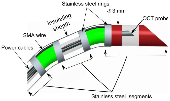
The discretely actuated steerable cannula is made of three straight segments that are connected by SMA actuators. The straight segments have a 1.4 mm inner diameter (ID) and a 1.65 mm outer diameter (OD). The two ends of the SMA wires are connected on the outer surface of the straight segments to enable bending of the probe when the SMA is actuated. It is necessary that the two ends of the SMA are not connected to the same metallic component, otherwise no actuation will result. There is 1 mm clearance between the adjacent links to prevent short-circuit and the sheath annulus structure and the SMA actuators that join the straight segments are rigid enough to prevent bending during insertion into the soft tissue. The SMA wires are attached mechanically by crimping the wire at the tips via use of stainless steel rings and enamel-coated wires are wrapped around the tip of the SMA wires for electrical connection. Figure 1 shows the components of the cannula. After the assembly, the cannula has 1.4 mm ID and 3 mm overall OD. The lengths of each segment from the base to the tip is 6.05 cm, 4.05 cm and 3.05 cm, respectively. The length of each segment is defined as the length of the individual segment plus half of the clearance between the segments (0.5mm).
Figure 1.
Schematic of the cannula
There are some limitations of the current design. Since the straight segments are conductive, only one SMA actuator can be used at each joint and a maximum number of three segments can be used in the current design. We connect negative (ground) connections in the middle link and the positive connections on the distal link and the proximal link. The actual prototype is shown in Figure 2. SMA actuators can be placed such that bending in different directions can be achieved. The hollow inner core of the cannula enables the delivery of both diagnostic and therapeutic tools to the appropriate location. An imaging window is also employed in the current design to demonstrate the probe’s use as a diagnostic tool for OCT imaging. It is important to note that, upon thermal actuation, bending occurs locally at the SMA location (the connection between two consecutive links) which can be advantageous for local steering, thereby enabling a small radius of curvature (see Figure 2). Sterilizability of the cannula is not a critical requirement for this work, as we do not anticipate reusing the cannula after the procedure is complete.
Figure 2.
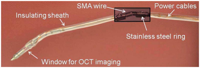
The 2-DOF cannula prototype
2.3 POSE TRACKING USING OPTICAL FLOW
A Micron Tracker (Claron Technologies Inc.) camera system is used for stereo imaging. To find the pose of the cannula, six markers are placed on the two-degree-of-freedom (2-DOF) prototype. There are two markers on each segment. The tracking algorithm is implemented using a pyramidal Lucas-Kanade optical flow algorithm and OpenCV libraries. The algorithm uses sum-of-squared intensity differences as measurements to minimize the errors for each tracking and works with sub-pixel accuracy (Bradski and Kaehler, 2008).
To register the initial configuration, six markers are clicked on the screen via a mouse on the images acquired from the left and right cameras at 15 fps. The 3D locations of the markers are calculated by triangulating the 2D location of the markers on left and right images. The pixel coordinates are then transformed into camera coordinates. A vector is drawn using the location of two markers in each segment (Figure 3) and the bending angle at each joint is calculated by finding the angle, αi (i = 1, 2), between the vectors drawn on the connected segments.
Figure 3.
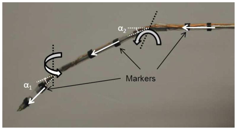
Six markers are placed on the cannula.
2.4 SHAPE MEMORY ALLOY POSITION CONTROL
There have been various approaches for controlling SMA actuators. There are primarily three feedback options for closed-loop control of SMA actuators: position, temperature and electrical resistance. Among these, direct measurement of strain can be challenging and impractical for compact designs where limited space is available. Using electrical resistance of the SMA is attractive for feedback control since it is an internal parameter and does not require an additional sensor (Dunlop and Garcia, 2002; Ikuta et al., 1988; Ma et al., 2004). Recovery strain of SMA is related to its temperature and the temperature of the SMA can also be used as a feedback signal to control the strain generated during phase transformation. Sensorless control of the SMA that does not rely on feedback, but instead depends on mathematical models to estimate the SMA strain have also been used for controlling SMA (Dutta and Ghorbel, 2005; Jayender et al., 2008). Curve fitting models treat the SMA as a black box and depend on the particular SMA actuator or setup used in developing the models. If the SMA actuator has to work in a environment different from the setup that was used to characterize it, the model may no longer be valid. Among these approaches, using a constitutive model based on temperature feedback is advantageous since only offline parameters need to be changed and these parameters can be obtained in advance through experiments (Brinson, 1993; Liang and Rogers, 1990; Tanaka, 1986). If the annealing parameters or the radius of curvature of the SMA actuator need to be changed, the model can still be used by modifying the offline parameters.
PWM has proven to be an effective method for SMA actuation (Ho and Desai, 2010; Ma and Song., 2003; Price et al., 2007). The main advantage of using a PWM-based controller is that it enables multiple joint motion simultaneously using a single power supply. We implemented PWM via use of a switching circuit. Two solid-state relays (SSRs) are used as switches and a Sensoray 626 DAQ card generates a digital on/off signals to control the switches. The discrete on/off control signal is used to convert continuously supplied current into an equivalent PWM output command to heat up the SMA wires.
We developed two PWM-based controllers. One of the controllers is a PWM-based vision feedback controller and the other is a temperature-based feedback controller. We developed the vision-based controller as we are eventually interested in image-guided control of the cannula in a MRI, CT, or ultrasound imaging environments. In our current prototype, we use stereo vision as the main feedback for position control of the cannula. We aim to eventually combine image-guided control with a temperature feedback controller so that the controller can switch to the temperature feedback controller when the image feedback from the imaging modality is not optimal.
2.4.1 Vision-based Feedback
Using the Micron Tracker camera system and the tracking algorithm, the difference between the desired angle and the current angle is updated at each frame. The heating time of each SMA wire, ti, is computed using a proportional controller given by Equation (2) where is the desired bending angle for joint i, and is the current joint angle of joint i. A control command, ti, represents the interval in which the switch for the selected SMA wire is closed and current is supplied to the corresponding SMA wire for ti seconds. The heating times are updated at each frame and the proportional gain, k, can be adjusted based on the task requirement.
| (2) |
The control scheme can be described as follows: at each frame, the position error for the first and second joint are calculated using the stereo image couples and the corresponding t1 and t2 values are updated. The first joint is then actuated for t1 seconds and after this interval is over the corresponding switch of the first joint is opened and the switch for the second joint is closed to actuate the second joint for t2 seconds. By switching the current between SMA wires, both SMA wires can be simultaneously actuated with the same power supply. The heating interval, t, is limited to an upper value tmax, to ensure that both SMA wires are monitored in each heating cycle, T.
2.4.2 Temperature Feedback
To control the temperatures of SMA wires, the same approach can be applied and PWM can be used to supply current to heat the SMA wires. We use a mini resistance temperature detector (RTD) sensor from Alpha Technics to measure the temperature of the SMA wire. The heating time is given by Eqn. (3) where is the desired temperature for SMA actuator i, and is the current temperature of the SMA actuator at joint i.
| (3) |
The SMA transformation is a heat-driven process and therefore its response time is limited. By increasing the current input to the SMA actuators, the response time can be improved. PWM is mainly used to drive the SMA actuators and the heating interval of each actuator is determined by the vision-based feedback and the temperature feedback controllers. In the vision-based feedback controller, the bending angle is directly measured and that is used to generate the appropriate control signal to actuate a particular SMA, while in the temperature-based feedback controller, the strain in the SMA wire is correlated with the temperature as well as the external stress acting on the SMA through the constitutive model of the SMA. The constitutive model of the SMA eventually provides the correlation between the temperature of the SMA wire and the bending angle (details in Section 3.2). The controllers described in this section will be used to characterize the SMA actuator.
3 EXPERIMENTS AND RESULTS
We first test the performance of the PWM-based controllers that are used for characterizing the SMA actuators. The constitutive model used for modeling the phase transformation of the SMA material is introduced next along with the details of the SMA characterization procedure. We also carry out a blocked force test to find the maximum force that can be generated by the SMA actuator. A test inside the gelatin demonstrates that the cannula can move inside a medium which requires substantial force to move the joints of the cannula.
3.1 TESTING OF PWM CONTROL
3.1.1 Vision-based Control
To verify the position control algorithm, both links were actuated up to 11°. The period, T, was chosen as 500 ms and the controller stopped sending control signal when the error is less than 0.5°. The change of bending angle and the corresponding PWM command signal are shown in Figure 3.1.2.
3.1.2 Temperature Control
To verify the temperature control algorithm, the first link was heated to 44°C. The period, T, was chosen to be 1000 ms. The change of temperature and the corresponding PWM command signal is shown in Figure 5.
Figure 5.
a) Temperature vs. time for the first joint b) PWM command signal
3.2 SHAPE MEMORY ALLOY ACTUATOR CHARACTERIZATION
SMA characteristics are primarily dependent on the external stress, strain and temperature and their associated time derivatives (Brinson, 1993; Liang and Rogers, 1990; Tanaka, 1986). These variables are interdependent and the SMA behavior is a nonlinear function of these variables. Most of the constitutive models have been developed for quasistatic loading, and as such, it is assumed that the material at each instant is in thermodynamic equilibrium. Since stress is a function of temperature T, the martensite volume fraction λ, and strain ε, the material constitutive relation in the differential form is given by (Tanaka, 1986):
| (4) |
This leads to a general expression:
| (5) |
where E(ε, λ, T) represents the modulus of material, Ω(ε, λ, T) is transformation tensor and θ(ε, λ, T) is thermal coefficient of expansion for the SMA material. Since the strain in the SMA due to thermal expansion is significantly lower than the strain due to phase transformation, this coefficient is normally neglected. We used the model developed by Tanaka (Tanaka, 1986) to characterize the SMA actuator. In Tanaka’s model, the strain, ε, temperature, T, and martensite volume fraction, λ, are assumed to be the only state variables. The stress, σ, in the material is calculated from these quantities. From Equation 5, the constitutive equation is derived as (Tanaka, 1986):
| (6) |
where E is the Young’s modulus in the elastic regime of the material, θ is a thermoelastic constant, and Ω is the phase-transformation constant. The terms associated with subscript ‘o’ refer to the initial state of the material. The elastic modulus is defined as:
| (7) |
If we consider a material at a temperature below the martensite finish (T < Mf ) and the zero stress/strain condition (εo = σo = 0), the material will be completely in the martensite phase. From Equation 6 the transformation constant, Ω, can be determined as:
| (8) |
where εL is the maximum recoverable strain. Tanaka’s model assumes an exponential function for the martensite volume fraction. During the martensite to austenite (M → A) transformation, λ is given by:
| (9) |
where aA, bA are constants defined as:
| (10) |
and Ca is called the stress influence coefficient. To fully characterize the SMA wire we need to find the transformation temperatures and the stress influence coefficient.
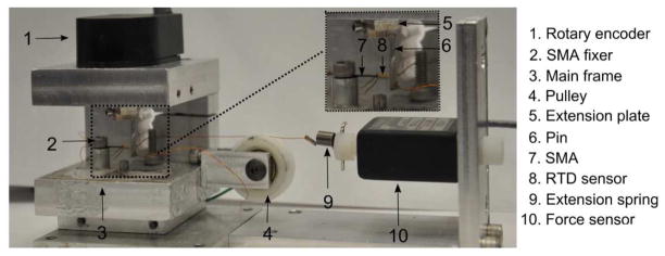
The experimental setup shown in Figure 6 was used to characterize the SMA wire. The apparatus consists of a rotary encoder and a pin attached a fixed distance, L, from the center of the encoder. Based on the geometry of the experimental apparatus, the relationship between the encoder reading, θ, and the radius of curvature, r, can be found using Equation 11, where origin, p1, is defined as the location of the SMA fixer and p2(x,y) is the location of the encoder axis (see Figure 7). There is also a pulley mounted on the main frame and different external loadings can be applied on the SMA wire by hanging a weight. We can apply variable external loading on the SMA wire using the extension spring that is connected directly to the force sensor (see Figure 7). There is a cable connected to the SMA wire at point p5, and it can be routed around the screw and connected to a mass via a pulley or it can be connected to the extension spring depending on what type of external loading we want to apply. To minimize the effect of air flow on the SMA characterization procedure, we placed a transparent box on the experimental apparatus during the experiments.
Figure 6.
Setup used for SMA characterization
Figure 7.
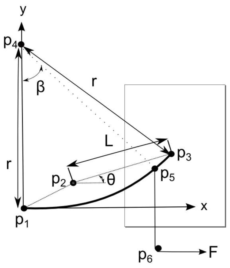
Geometric relations of the setup
| (11) |
We now discuss the detail step-by-step characterization procedure for SMA actuator used in our experiments.
3.2.1 Step 1: Finding The Transformation Temperatures
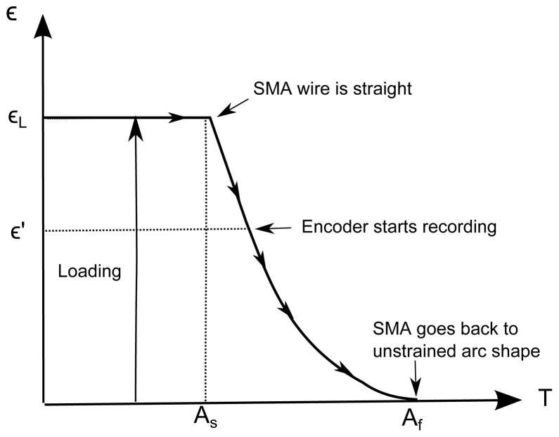
To find the transformation temperatures during the heating of SMA wire, As and Af, and to measure the relationship between the strain in the SMA wire and its temperature, the external stress on the SMA wire should be kept constant. As the strain in the SMA wire is computed from the radius of curvature, we analyze the motion from θ = 0° (ε′ as shown in Figure 8). Initially, the SMA wire is at room temperature in the straight configuration and as the wire is heated beyond As, the wire starts to transform from the martensite phase to the austenite phase. The encoder starts recording when the SMA wire contacts the pin. Above Af, the SMA wire recovers its unstrained arc shape.
Figure 8.
Strain vs. temperature
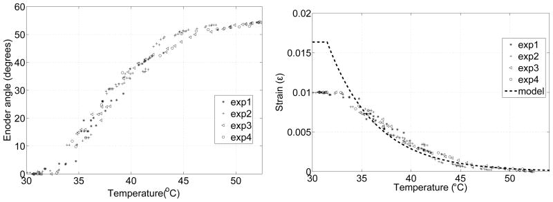
Four experiments were carried out to find the strain-temperature relation of the SMA wire. To ensure good thermal contact between the RTD sensor and the SMA wire, a thermally conductive paste (Omegatherm 201) was used. To ensure quasistatic deformation, the temperature of the SMA wire was increased incrementally in steps and it was maintained at each intermediate temperature. Figure 9a shows the plot of encoder vs. temperature and Figure 9b shows the plot of strain vs. temperature along with the relationship from the model using Equation 1. The transformation temperatures As and Af were determined to be 31.5°C and 54°C, respectively. In the model, maximum strain εL is modeled to be the strain when the SMA wire is deformed into a straight wire and bending angle, α, is 0 degree. The maximum strain is 0.01624 and that corresponds to 1.564 cm radius of curvature.
Figure 9.
a) Encoder readings, b) Strain vs. temperature under no loading
3.2.2 Step 2: Finding The Stress Influence Coefficient
Once the transformation temperatures are found, the next step is to find the stress influence coefficient. Stress influence coefficient quantifies the effect of stress on the phase transformation temperatures. Different external loadings can be applied to the SMA actuator by hanging a mass via the pulley. As the temperature of the SMA wire increases, the location of the point p5, where the cable is connected to the SMA actuator, changes. Let s be the distance between the origin (SMA fixer) and point p5. For pure bending, the length of the wire remains unchanged and we can thus find the location of point p5 using:
| (12) |
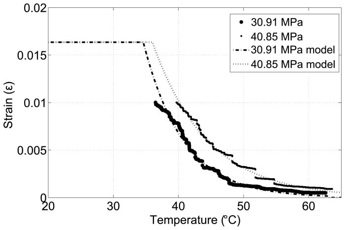
where β = s/r. The force direction can be computed by drawing a line between points p5 and p6. The angle between the force vector and the x axis ranges between 84.74° and 90°. Since sin(84.64°)= 0.9958 ≈ 1, we can assume that the force acting on point p5 is constant and hence characterize the SMA using the maximum stress at point p5. Figure 10 shows the strain-temperature relation of the SMA actuator under two different loadings. The As values for 30.91 MPa and 40.85 MPa are 35°C and 36°C, respectively. The corresponding stress influence coefficient, Ca, can be calculated as 8.8 MPa/°C and 9 MPa/°C and we use the average value of Ca = 8.9 MPa/°C.
Figure 10.
Strain vs. temperature under external loading
3.2.3 Step 3: Testing Under Variable Loading
In order to investigate the behavior of the SMA wire and evaluate the model under variable loading, we have used the extension spring attached to the force sensor. As the SMA actuator transforms into its original shape from its prestrained straight condition, it pulls the cable connected to the extension spring and the force exerted by the spring can be recorded using the force sensor. Figure 11a shows that the external stress can be modeled as a straight line for this experimental setup. Figure 11b shows the strain in the SMA wire and the strain calculated using Tanaka’s model with material constants Ca = 8.9MPa/°C, EM = 28GPa and EA = 78GPa.
Figure 11.
a) External stress acting on the SMA wire, b) Strain-temperature relation under variable loading
3.2.4 Step 4: Finding The Relationship Between The Bending Angle And The Strain
We define the bending (joint) angle as the angle between consecutive links, and the geometric relation between the strain in the SMA wire and the corresponding bending angle needs to be determined. To find this relation, two small links were attached at the tips of the SMA wire and markers were placed on the links and the tracking algorithm was used to find the bending angle between the links (Figure 12). Figure 13a shows the change in bending angle with the strain calculated using Tanaka’s model at that temperature and the exponential (R2 =0.9819) curve fit is given by:
| (13) |
Figure 12.
Change in bending angle as SMA wire is heated
Figure 13.
a) Relation between strain and bending angle, b) characterization of the cannula
3.2.5 Step 5: Characterizing The Dicretely Actuated Steerable Cannula
If we repeat the experiment to find the strain-temperature relation under no stress after the cannula is assembled, we see that the transformation temperatures of the SMA actuator increases (Figure 13b) due to the induced stress by the sheath and the crimps on the SMA wire. Finding the individual effects of the crimps and the sheath on stress is challenging due to the fact that the stress caused by the stainless steel rings (crimps) is not uniform along the SMA wire and the sheath thickness is not uniform since it conforms to the shape of the cannula. We can extend the model developed for the SMA actuator and capture the overall effect of the sheath and the crimps by selecting As and Af in the model as 37°C and 68°C, respectively. Any external stress can be substituted in Equation 6 to find the change in strain (and thus the bending angle) with temperature.
If the external stress is known, the strain in SMA is only a function of its temperature. Tanaka’s model enables us to find the change in strain with temperature by solving the nonlinear equation given by Equation 6. The desired temperature of the wire (and hence the strain) can then be controlled using the PWM-based temperature controller. To determine the external stress acting on the SMA actuators, there are two possible options that we consider. First, incorporating a force sensor in the cannula design enables the measurement of the external stress. The other option is to incorporate tissue models into the Tanaka’s model so that the external stress term can be related to the desired deformation that the cannula will cause in the soft tissue.
3.3 TESTING OF THE MAXIMUM FORCE
To quantify the maximum force that can be generated by the SMA wires, we used the experimental setup in Figure 14. A MBD-2.5 force sensor (Transducer Techniques Inc.) was used to measure the maximum force generated at the joints. The cannula and the force sensor were fixed during the measurements. Thus, the SMA wire was kept at zero strain which enabled us to measure the maximum force exerted, Fblock, at the joint. A continuous 1.9 Amp current was supplied to the SMA wire. All the prototypes we developed in our laboratory generated a maximum force of between 2.3–2.7 N at each joint.
Figure 14.
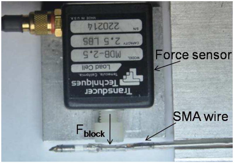
The experimental setup used for force measurement
3.4 TESTING INSIDE GELATIN
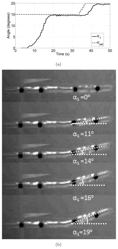
To mimic motion in tissue, the cannula motion was evaluated in a phantom of Knox Gelatine (Kraft Foods Inc.). Three packets of gelatin were dissolved in cold water inside a 200 ml cup. Two cups of boiling water were added to the mixture, which was kept inside a refrigerator until it was fully hardened. During the experiments, the gelatin was maintained at 15°C. A small hole was drilled on the side of the container and the cannula was clamped between two steel blocks to keep it fixed during the experiment. The period, T, was chosen to be 1000 ms and the controller stopped sending control signals when the error was less than 1 degree.
Initially, the first joint was actuated to 15° and then the desired angle was incremented by 1° up to 20°. The change in bending angle with time is shown in Figure 15a. The initial actuation took relatively longer compared to actuation in air (Figure 3.1.2a) due to heat loss from the SMA wires to gelatin as the transition temperature of the final SMA wire was substantially higher than the temperature of the gelatin (15°C). The snapshots from the experiment are shown in Figure 15b. It is clear from this experiment that the SMA actuator at the joint can exert substantial force to bend inside a medium where a significant force is required to move the medium around.
Figure 15.
a) Change of bending angle inside translucent gelatin, b) the cannula moving inside the gelatin
4 TRAJECTORY PLANNING AND EXECUTION OF THE CANNULA
There have been various approaches to the trajectory planning of flexible needles and cannulas in the past decade. Motion planning techniques requiring the minimization of a suitable cost function have been widely used. Additional constraints may be imposed on trajectory planning such as obstacle avoidance and minimum path. Duindam et al. (2008) discretized the control space of the flexible needles and formulated the optimization problem using a cost function that minimizes the control effort and path length. Park et al. (2005) applied a numeric diffusion-based method for trajectory planning of flexible needles in an obstacle-free 3D environment. Glozman and Shoham (2007) used fluoroscopic images of the tissue before needle insertion to find the location of the obstacle, needle tip, and the target, and through these three points they passed a spline trajectory to find the insertion trajectory. Xu et al. (2008) used rapidly exploring random trees to find the feasible paths in a configuration space. For flexible needles, finite element modeling has also been used for planning paths around obstacles in deformable tissue (Alterovitz et al., 2005). Lyons et al. (2010) planned trajectories for the active cannula for lung biopsy procedures by using a cost function that depends on the tubular environment geometry. These methods cannot be directly applied to the discretely actuated steerable cannula since these devices are structurally different. For the discretely actuated steerable cannula, it is also difficult to control the strain rate (and hence the joint velocity) of the SMA actuator using the PWM-based controllers since we are only able to control and maintain the bending angle. Thus, we followed a kinematic approach for trajectory planning and execution of the cannula trajectory. We now present our approach to generate a minimum path between the desired and final configurations in an obstacle-free environment. Using the notation in Murray et al. (1994), the twist coordinate for a revolute joint is defined as:
| (14) |
where ωi ∈ R3 is a unit vector in the direction of the twist axis and qi ∈ R3 is any point on the axis. For a prismatic joint, the twist coordinate is given by:
| (15) |
where vi ∈ R3 is a unit vector pointing in the direction of translation. For the cannula in Figure 16:
Figure 16.
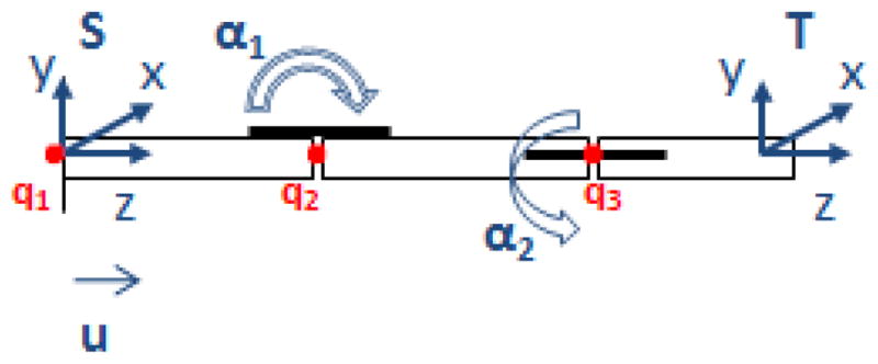
The schematic used for the forward kinematics map
The forward kinematics map can be written as:
| (16) |
where
| (17) |
The equations were derived for the general case where the SMA at the second joint can be placed at an arbitrary angle β with respect to the first joint. In our current prototype β is 90°; l1, l2 and l3 are 60.5, 40.5 and 30.5 mm respectively. gst can be represented as:
| (18) |
where R ∈ SO(3) is the orientation of frame T, relative to frame S and p ∈ R3 is the position vector of the origin of frame T from the origin of frame S. The 3D position of the tip, p(q), is given by:
| (19) |
where
The infinitesimal arc length, dγ, can be written as:
| (20) |
where gij are the terms of the metric tensor, G (G is symmetric). The individual terms of the metric tensor, G, are given by:
| (21) |
In this case, we are interested in finding curves of zero acceleration, namely geodesics on the manifold. The geodesic equation can be written as (Do Carmo, 1992):
| (22) |
where is the Christoffel symbol defined in terms of the elements of the metric tensor as:
| (23) |
where glk is the entries of the inverse of G. Equation (22) produces three second-order differential equations which can be converted into six first-order differential equations. The trajectory for the minimum distance between the desired initial and final configurations can be computed numerically by solving a two-point boundary value problem. The trajectory is parameterized by η, where η ranges between 0 (initial configuration) and 1 (final configuration). The bvp4c function in MATLAB was used to solve the problem. If the boundary conditions are selected as:
| (24) |
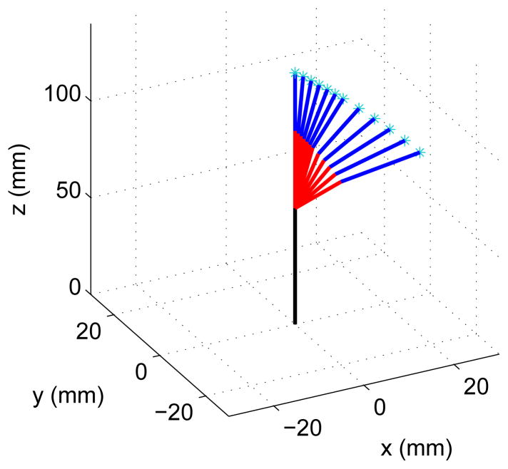
the resulting motion is shown in Figure 17 where the joint angles α1 and α2 change linearly with respect to the parameter η from 0–20° and 0–30°, respectively.
Figure 17.
Motion in 3D
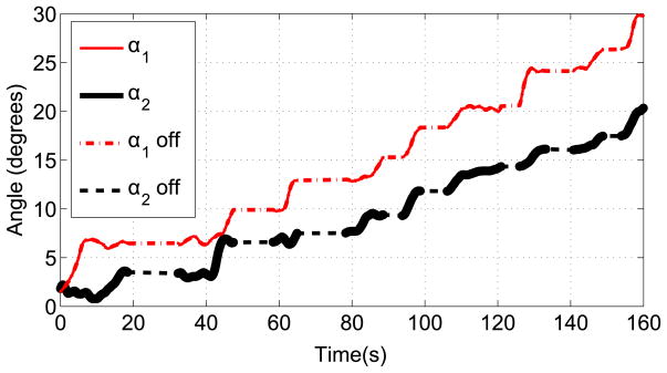
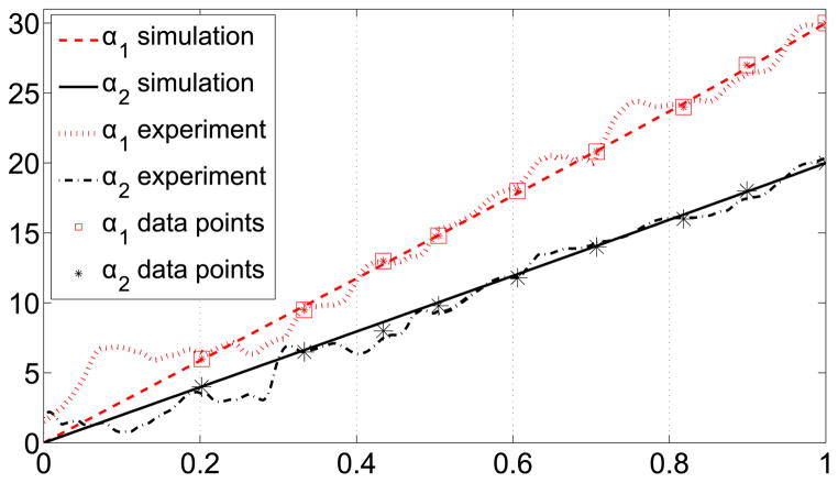
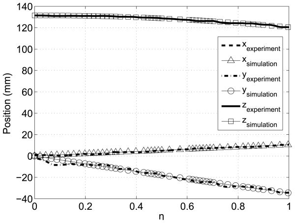
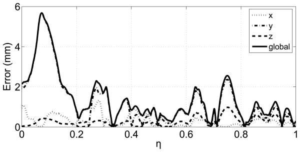
To execute the trajectory-planning scheme, we divide the trajectory into nine intervals by selecting nine data points along the trajectory. We aim to control the position and achieve the desired bending angle at these nine locations along the trajectory. Table 1 shows the data points and the desired bending angles. Initially, the angles corresponding to the first data point were entered as the desired bending angles. Once both of the joints reached the desired angles, the angles corresponding to the next data point were entered as the new desired angles. When the markers were along the line that corresponds to bending angles α1 = 0° and α2 = 0°, we observed that there are variations in the bending angle readings. This makes it difficult to control bending the angles that are close to zero, angles less than two degrees in particular. Therefore, a longer interval was selected for the first interval. Figure 18 shows the change of bending angles with time and αoff represents the interval when the new desired inputs were entered. The trajectory between each arc length interval is locally a geodesic. For each interval, the reparametrization between the parameter η and time is given by Equation (25), where the subscripts i and j represent the starting point of the interval when the desired angles were entered and the final point when both links reached the desired angles of the interval, respectively. The data points showing the desired angles for the intervals and the results of the simulation and experiment are shown in Figure 19. The 3D position of the tip of the cannula can be calculated from the forward kinematics map and is given in Figure 20. The errors along the trajectory are given in Figure 21 and the global error between the final configuration and the target location is 0.29 mm. The maximum error occurs in the first interval due to the fact that this interval is longer than the other intervals and therefore the resolution is smaller for this interval (see Figure 21).
Table 1.
Data points selected along the trajectory and corresponding desired bending angles
| η | α1 | α2 |
|---|---|---|
| 0.202 | 6° | 4° |
| 0.303 | 9.5° | 6.5° |
| 0.424 | 13° | 8° |
| 0.505 | 14.8° | 9.8° |
| 0.606 | 18° | 11.8° |
| 0.707 | 20.8° | 14° |
| 0.818 | 24° | 16° |
| 0.899 | 27° | 18° |
| 1 | 30° | 20° |
Figure 18.
The change of joint angles with time
Figure 19.
The change of joint angles with η
Figure 20.
The change of 3D position with time
Figure 21.
Errors along the trajectory
| (25) |
5 OCT IMAGING EXPERIMENTS
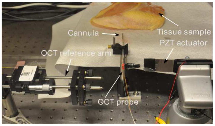
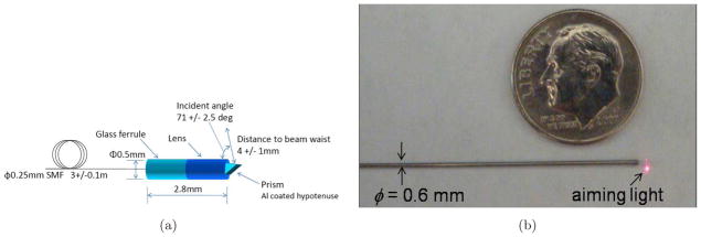
The feasibility of using the OCT-integrated cannula for tissue imaging was tested on two different biological samples. The aim of the experiments presented in this section is not to quantify the performance of the particular OCT probe, but to verify the imaging capability of the cannula during bending since we are interested in using the cannula to enable in situ imaging at the target location. The experimental setup shown in Figure 22, consists of the biological sample, the PZT actuator, the OCT probe, the cannula, and a OCT reference arm. The sample arm consists of a fiber-based probe (Figure 23). The tip of the OCT probe consists of a gradient-index lens (GRIN) and a micro mirror to deflect the beam. The transverse resolution is 15 μm. The OCT interference signal returned from the sample and reference arms is detected by a balanced photodetector and recorded with uniform optical frequency. Discrete Fourier transform (DFT) is performed on the data to produce an axial depth profile of the sample (A-line). The OCT probe is actuated at the proximal end by a piezoelectric actuator. The actuator is also synchronized with image acquisition and operated at 14 fps.
Figure 22.
Experimental setup for the OCT system
Figure 23.
a) Details of the OCT probe and b) the actual OCT probe
First, the cannula and the OCT system were tested on chicken breast. The OCT probe was inserted into the cannula before insertion into soft tissue. A current of 1.4 A was supplied to the first joint. The same procedure was carried out inside porcine tissue as well. The images were recorded throughout the bending process and are shown in Figure 24. The images are placed with increasing bending angle from left to right, the first one showing the initial OCT image. The images of connective tissues in porcine tissue and the muscle fibers in chicken breast can be clearly resolved by the imaging system before and during bending. As the bending angle increases, the scanning range of the OCT probe in the imaging window becomes smaller and smaller and finally stops. Figure 25 shows the histogram of the four images for the two tests. The images are numbered from 1 to 4 from left to right. The histogram of the images during bending indicates that the images have very similar contrast levels, except the image corresponding to the seized probe (last images). When the probe was stuck, the pixel values at different lateral positions were from the same A-scan and thus, the image appeared as multiple straight lines. These straight lines increase the histogram distribution on the high intensity portion. These results show that the image quality is not affected by the bending of the cannula.
Figure 24.
a) Microstructures of chicken breast and b)Microstructures of porcine tissue
Figure 25.
a)Histogram of chicken breast OCT images and b) histogram of porcine tissue OCT images
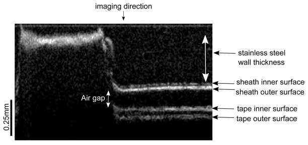
In our initial experiments, we were not able to see the cannula inside the tissue, and we do not have any information about the angle at which the OCT probe contacts the inner wall. In the second part of the experiments, we aimed to quantify the angle at which this contact takes place. The Micron Tracker camera was placed in front of the setup to track the bending angle during OCT imaging and we have wrapped a tape around the imaging window. This setup enabled us to measure the bending angle at which the scanning range of the OCT probe would start to decrease. Since tape was only wrapped around the imaging window, the markers were clearly detected and we were able to use the pose-tracking algorithm to measure the bending angle. The inner wall of the cannula, sheath and tape can be clearly seen in the OCT image (see Figure 26) and OCT images at various angles are shown in Figure 27. As the bending angle increased, the OCT probe got closer to the inner wall and the decrease in distance between the OCT probe and imaging window at larger angles limits the field of view. The OCT probe contacts the inner wall at 8.334°. The PZT actuator also causes lateral vibration which becomes more apparent when we look at the cannula’s inner wall in Figure 26. Note that the bending angle of the OCT probe itself is only limited by the nitinol tubing that is used to protect the probe from the environment. The maximum bending angle that can be achieved with the OCT-integrated cannula, can be improved by incorporating a mechanism inside the cannula that would hold the OCT probe in place during bending to prevent it from contacting the inner wall.
Figure 26.
The inner wall of the cannula, sheath and tape
Figure 27.
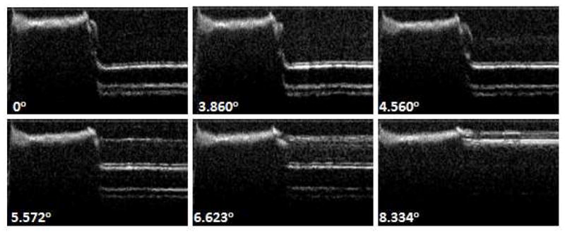
OCT images at various angles
6 CONCLUSION
We have presented a compact design of a discretely actuated steerable cannula with SMA actuators. Each segment of the cannula is independently actuated and the design enables the placement of SMA actuators along the length of the cannula at discrete locations. The SMA actuators are annealed to have an arc shape in the austenite phase and this annealing process changes the phase transformation temperatures of the SMA actuator. To characterize the SMA actuator and use the temperature feedback to control the bending angle, the phase-transformation temperatures and the effect of stress on the SMA actuator were determined through experiments. There is no standard procedure or experimental setup for characterizing an SMA wire that is trained to generate bending forces, and hence we presented an experimental setup and a step-by-step procedure for characterizing an SMA actuator. The SMA actuator was modeled using Tanaka’s model and we can hence use temperature as the feedback to control each joint angle. A PWM-based control scheme with vision feedback and temperature feedback was successfully implemented to demonstrate local actuation of the cannula and the vision-based feedback controller was used to control and maintain the joint angle inside gelatin.
Since the bending of each joint is controlled by heating the SMA wire, the process is slow and presents a challenge to control the strain rate of the SMA actuator in trajectory planning. Therefore, we presented a trajectory planning algorithm with geodesics and a trajectory execution scheme that does not require control of the the strain rate. We have demonstrated the capability of the cannula to aid in diagnosis, with the use of an OCT probe. Hence, the discretely actuated steerable cannula can potentially serve as a delivery mechanism for theranostic (diagnostic and therapeutic) interventions.
There are several areas of future work based on the successful design and evaluation of the discretely actuated cannula presented in this paper. First, we are interested in using two pairs of antagonistic SMA actuators at each joint which will enable each joint to bend in two separate directions. Secondly, in this work, the vision-based and temperature-based position controllers were not used simultaneously. Since our eventual goal is to use the discretely actuated steerable cannula in an imaging environment such as MRI, CT, or ultrasound, we plan to develop a high-level controller to switch between image-based and temperature-based controllers for position control, especially when there is poor image quality from the imaging system. Thirdly, we are also looking into incorporating tissue models in the control framework to enable better trajectory planning. The work presented in this paper is the first step towards realizing the aforementioned goals.
Figure 4.
a) Bending angle vs. time for the cannula and b) PWM command signals for the two SMA wires
Acknowledgments
This work was supported in part by the National Science Foundation (NSF) grant 0704138, 2011 UMCP-UMB research seed grant program, and the National Institutes of Health (NIH) grant R01EB008713, R21EB012215-01A1 and R21DK088066-01A1.
References
- Alterovitz R, Goldberg K, Okamura AM. Planning for steerable bevel-tip needle insertion through 2d soft tissue with obstacles. Proceedings of the 2005 IEEE International Conference on Robotics and Automation. 2005 Apr;:1640–1645. [Google Scholar]
- Ayvali Elif, Desai Jaydev P. Towards a discretely actuated steerable cannula. IEEE International Conference on Robotics and Automation; Minnesota, USA. May 2012; 2012. p. 1418. [DOI] [PMC free article] [PubMed] [Google Scholar]
- Ayvali Elif, Ho Mingyen, Desai Jaydev P. A novel discretely actuated steerable probe for percutaneous procedures. 12th International Symposium on Experimental Robotics; New Delhi, India. 2010. [Google Scholar]
- Bradski G, Kaehler A. Learning OpenCV: Computer Vision with the OpenCV Library. O’Reilly Media; 2008. [Google Scholar]
- Brinson LC. One-dimensional constitutive behavior of shape memory alloys: Thermomechanical derivation with non-constant material functions and redefined martensite internal variable. Journal of Intelligent Materials and Structures. 1993;4:229–242. [Google Scholar]
- Churchill CB, Shaw JA, Iadicola MA. Tips and tricks for characterizing shape memory alloy wire: part 2-fundamental isothermal response. Experimental Techniques. 2009;33(1):51–62. [Google Scholar]
- Do Carmo MP. Riemannian geometry, Mathematics: Theory & Applications. Birkhauser Boston, Inc; 1992. [Google Scholar]
- Duindam V, Alterovitz R, Sastry S, Goldberg K. Screw-based motion planning for bevel-tip flexible needles in 3d environments with obstacles. IEEE International Conference on Robotics and Automation; may 2008; 2008. pp. 2483–2488. [DOI] [PMC free article] [PubMed] [Google Scholar]
- Dunlop R, Garcia AC. A nitinol wire actuated stewart platform. Australasian Conference on Robotics and Automation; nov. 2002.pp. 27–29. [Google Scholar]
- Dupont PE, Lock J, Itkowitz B, Butler E. Design and control of concentric-tube robots. IEEE Transactions on Robotics. 2010 Apr;26(2):209–225. doi: 10.1109/TRO.2009.2035740. [DOI] [PMC free article] [PubMed] [Google Scholar]
- Dutta SM, Ghorbel FH. Differential hysteresis modeling of a shape memory alloy wire actuator. IEEE/ASME Transactions on Mechatronics. 2005;10(2):189–197. [Google Scholar]
- Glozman D, Shoham M. Image-guided robotic flexible needle steering. IEEE Trans Robot. 2007;23(3):459–467. [Google Scholar]
- Haga Y, Esashi M. Small diameter active catheter using shape memory alloy coils. Trans IEE of Japan. 2000;120(11):509–514. [Google Scholar]
- Hisaaki Tobushi, Kikuaki Tanaka. Deformation of a shape memory alloy helical spring: Analysis based on stress-strain-temperature relation. JSME international journal Ser 1, Solid mechanics, strength of materials. 1991;34(1):83–89. [Google Scholar]
- Ho Mingyen, Desai JP. Towards a mricompatible meso-scale sma-actuated robot using pwm control. 3rd IEEE RAS and EMBS International Conference on Biomedical Robotics and Biomechatronics (BioRob); sept. 2010.2010. pp. 361–366. [Google Scholar]
- Ikuta K, Tsukamoto M, Hirose S. Shape memory alloy servo actuator system with electric resistance feedback and application for active endoscope. IEEE International Conference on Robotics and Automation; apr 1988.1988. pp. 427–43. [Google Scholar]
- Jayender J, Patel RV. Master-slave control of an active catheter instrumented with shape memory alloy actuators. IEEE/RSJ International Conference on Intelligent Robots and Systems; nov. 2007.2007. pp. 759–764. [Google Scholar]
- Jayender J, Patel RV, Nikumb S, Ostojic M. Modeling and control of shape memory alloy actuators. IEEE Transactions on Control Systems Technology. 2008;16(2):279–287. [Google Scholar]
- Lagoudas Dimitris C. Shape Memory Alloys Modeling and Engineering Applications. Springer; 2008. [Google Scholar]
- Liang C, Rogers CA. One-dimensional thermo mechanical constitutive relations for shape memory material. Journal of Intelligent Materials and Structures. 1990;1(2):207–234. [Google Scholar]
- Lyons LA, Webster RJ, Alterovitz R. Planning active cannula configurations through tubular anatomy. IEEE International Conference on Robotics and Automation; may. 2010.2010. pp. 2082–2087. [Google Scholar]
- Ma N, Song G. Control of shape memory alloy actuator using pulse width modulation. Smart Mater Struct. 2003;12:712–719. [Google Scholar]
- Ma N, Song G, Lee H-J. Position control of shape memory alloy actuators with internal electrical resistance feedback using neural networks. Smart Mater Struct. 2004;13(4):777–783. [Google Scholar]
- Murray RM, Li Z, Sastry SS. A Mathematical Introduction to Robotic Manipulation. CRC Press; 1994. [Google Scholar]
- Park W, Kim JS, Zhou Y, Cowan NJ, Okamura AM, Chirikjian GS. Diffusion-based motion planning for a nonholonomic flexible needle model. Proceedings of the 2005 IEEE International Conference on Robotics and Automation; april 2005.pp. 4600–4605. [Google Scholar]
- Pfeiffer C, DeLaurentis K, Mavroidis C. Shape memory alloy actuated robot prostheses: initial experiments. IEEE International Conference on Robotics and Automation; 1999. pp. 2385–2391. [Google Scholar]
- Price AD, Jnifene A, Naguib HE. Design and control of a shape memory alloy based dexterous robot hand. Smart Mater Struct. 2007;16:1401–1414. [Google Scholar]
- Sears P, Dupont P. A steerable needle technology using curved concentric tubes. IEEE/RSJ International Conference on Intelligent Robots and Systems; oct. 2006.2006. pp. 2850–2856. [Google Scholar]
- Shaw JA, Churchill CB, Iadicola MA. Tips and tricks for characterizing shape memory alloy wire: Part 1differential scanning calorimetry and basic phenomena. Experimental Techniques. 2008;32(5):55–62. [Google Scholar]
- Tanaka K. A thermomechanical sketch of shape memory effect: Onedimensional tensile behavior. Res Mechanica. 1986;18:251–263. [Google Scholar]
- Veeramani AS, Buckner GD, Owen SB, Cook RC, Bolotin G. Modeling the dynamic behavior of a shape memory alloy actuated catheter. Smart Mater Struct. 2008;17(1):1–14. [Google Scholar]
- Webster RJ, Cowan NJ, Chirikjian G, Okamura AM. Nonholonomic modeling of needle steering. Proc. 9th International Symposium on Experimental Robotics; 2004. pp. 35–44. [Google Scholar]
- Webster RJ, Okamura AM, Cowan NJ. Toward active cannulas: Miniature snake-like surgical robots. IEEE/RSJ International Conference on Intelligent Robots and Systems; oct. 2006.2006. pp. 2857–2863. [Google Scholar]
- Xu J, Duindam V, Alterovitz R, Goldberg K. Motion planning for steerable needles in 3d environments with obstacles using rapidly-exploring random trees and backchaining. 2008 IEEE International Conference on Automation Science and Engineering. 2008 Aug;:41–46. [Google Scholar]


