Abstract
Calcium carbonate (CaCO3) is one of the most abundant minerals and of high importance in many areas of science including global CO2 exchange, industrial water treatment energy storage, and the formation of shells and skeletons. Industrially, calcium carbonate is also used in the production of cement, glasses, paints, plastics, rubbers, ceramics, and steel, as well as being a key material in oil refining and iron ore purification. CaCO3 displays a complex polymorphic behaviour which, despite numerous experiments, remains poorly characterised. In this paper, we report the use of a segmented-flow microfluidic reactor for the controlled precipitation of calcium carbonate and compare the resulting crystal properties with those obtained using both continuous flow microfluidic reactors and conventional bulk methods. Through combination of equal volumes of equimolar aqueous solutions of calcium chloride and sodium carbonate on the picoliter scale, it was possible to achieve excellent definition of both crystal size and size distribution. Furthermore, highly reproducible control over crystal polymorph could be realised, such that pure calcite, pure vaterite, or a mixture of calcite and vaterite could be precipitated depending on the reaction conditions and droplet-volumes employed. In contrast, the crystals precipitated in the continuous flow and bulk systems comprised of a mixture of calcite and vaterite and exhibited a broad distribution of sizes for all reaction conditions investigated.
INTRODUCTION
Crystallisation has been studied for hundreds of years. Despite this, our understanding of the mechanisms by which crystals form in solution is remarkably limited. This can be largely attributed to the inherent challenges associated with the study of nucleation and crystal growth.1 Experimentally, the determination of nucleation mechanisms relies on analytical techniques that are able to characterise molecular-level processes occurring during the formation of transient critical nuclei a few nanometers in size (and their subsequent growth). Indeed, with the development of methods such as high resolution cryo-TEM, it has been possible to show that calcium carbonate and calcium phosphate appear to form by the aggregation of pre-nucleation clusters,2, 3 and it is now recognised that many crystals grow via an aggregation of precursor crystallites.4 Quantitative analysis of nucleation and growth rates, in contrast, depends on an ability to perform a large number of experiments under highly reproducible conditions. However, crystallisation in bulk solution is inevitably complicated by the presence of impurities, which are impossible to remove, and the presence of the container walls, which can themselves promote nucleation. Accordingly, nucleation of crystals in solution is invariably heterogeneous, as the energy barrier associated with the formation of a nucleus is reduced when the nucleus forms on an existing surface.5
One highly effective method for obtaining reproducible data is to perform crystallisation within droplets.6 These not only provide the opportunity to perform hundreds of experiments very quickly, but the small reaction volume is such that the majority of droplets do not contain impurities; those that do generate outlying data points and can in principle be excluded. To this end, levitated droplets7, 8 and droplets created using automated dispensing systems9, 10, 11 have previously been used to study homogeneous nucleation and to facilitate rapid screening of crystallisation conditions. Arrays of picolitre droplets formed on patterned self-assembled monolayers (SAMs) in contrast have provided an opportunity to study heterogeneous nucleation in confined volumes.12 As an elegant way of producing droplets under highly controlled conditions, microfluidic systems are also beginning to be explored as platforms for the study of crystal nucleation and growth in general.13 They provide excellent spatial and temporal control of temperature, pressure, pH, and reagent concentration and can be used to generate segmented flows, allowing the formation of monodisperse, pL-volume droplets at kHz rates. The volume contained within each droplet provides a well-defined and confined environment where homogeneous nucleation of crystals can be studied.14, 15 The potential of this approach has been established in the generation of high quality protein crystals for subsequent XRD analysis,16, 17, 18 the screening of potassium nitrate polymorphism,6 the investigation of nucleation phenomena,1, 19 and the screening of solubility diagrams.20
Herein, we describe the use of droplet-based microfluidics to investigate the precipitation of calcium carbonate under highly controlled conditions. To date, the only microfluidic approach reported for the synthesis of calcium carbonate has involved continuous-flow mixing of reagents at a T-junction.21, 22 These proof-of-principle studies demonstrated facile crystal formation, and extraction of crystals for off-chip characterization by scanning electron microscopy (SEM) showed predominantly calcite polymorphs present. Unfortunately, the unavoidable residence time distributions associated with continuous-flow reactors significantly reduce control over reaction times, leading to broad size distributions of the resulting crystals and therefore limited control over the crystal polymorph. These limitations can be avoided by adoption of a segmented flow regime, where reagents are encapsulated in within picoliter-volume droplets that do not interact with the channel walls and that move at a constant linear velocity (thus eliminating residence time distributions).
The fact that calcium carbonate can precipitate in a number of polymorphs under ambient conditions makes it an invaluable model system for understanding crystallisation of low-solubility minerals.23 Precipitation of CaCO3 within droplets provides a unique opportunity for investigating mineral precipitation in ultra-small volumes. This has relevance to many processes such as weathering and biomineralisation, which invariably occur in restricted volumes rather than in bulk solution.24, 25
EXPERIMENTAL METHODOLOGY
Preparation of microfluidic devices
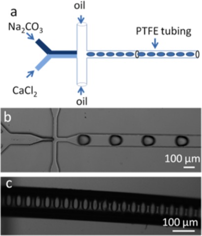
Microfluidic devices were fabricated using standard soft lithographic techniques.26 Briefly, the microchannel layout was designed using AutoCAD (Autodesk, San Rafeal, CA, USA) printed onto an acetate film mask (Circuit Graphics, Essex, UK) and then transferred to an SU8 master, which serves as the mould for subsequent soft lithography. The PDMS base and curing agent (Sylgard184, Dow Corning, Coventry UK) were mixed at a ratio of 10:1 (w/w) and poured onto the master. After curing at 65 °C for 90 min, the structured PDMS substrate was peeled off the master. Access holes at inlets were punched through the PDMS using a syringe needle, and the top layer was then joined with an unstructured PDMS layer and the entire assembly cured at 65 °C overnight. The device layout (Figure 1) comprised either two or three inlets, with all microchannels having a uniform cross section of 100 μm (width) × 50 μm (height). The wider section at the end of the reaction channel had a cross section of 300 μm (width) × 50 μm (height). Polytetrafluoroethylene (PTFE) tubing (Cole Palmer, Hanwell, UK) of 100 μm i.d. and 300 μm o.d. was inserted carefully into the outlet reservoir to extend the reaction channel and allow collection of product. Droplets enter the tubing undisturbed and well separated (Figure 1c). Reagents and carrier phase were delivered into and through the microfluidic devices using precision syringe pumps (PHD 2000, Harvard Apparatus, Holliston, MA, USA) at volumetric flow rates ranging from 1 μl/min to 10 μl/min. A high-speed camera (Phantom®, v 649, Vision Research, Bedford, UK) was used to image droplets using a 50 μs exposure time at a frame rate of 1000 frames per second (fps).
Figure 1.
(a) Schematic of the microfluidic system used for the droplet-based synthesis of calcium carbonate. Droplets are formed when two streams of reagents are broken by an FC-40 oil flow inside the orifice of a flow-focusing device. The droplets then enter the PTFE tubing undisturbed. (b) Image of droplets formed using this configuration. (c) Image of PTFE tubing containing aqueous droplets of calcium carbonate. Droplets are of a uniform size and are well separated by the continuous phase.
Precipitation of calcium carbonate
Calcium carbonate was precipitated in individual droplets generated within the microfluidic device. Control experiments in which the CaCO3 was precipitated in either a continuous flow microfluidic device or bulk solution were used as controls. On-chip precipitation of calcium carbonate, in both continuous or segmented flow, was achieved by delivering small volumes of equimolar calcium chloride (Sigma Aldrich, Gillingham, UK) and sodium carbonate (Sigma Aldrich, Gillingham, UK) solutions (between 4 and 12 mM) through the two inlets at a flow rate of 1 μl/min. While this set-up was sufficient for the continuous flow experiments, droplets were generated by flow focusing the aqueous stream with FC40 oil (3M, Bracknell, UK) containing 2.5% Raindance surfactant (Raindance Technologies, Lexington, MA) at a flow rate of 3 μl/min. The reaction products in both cases were collected at the outlet of the PTFE tubing by rapid delivery to a 0.2 μm pore size, track-etch membrane (Millipore, Billerica, USA), washing with ethanol under suction, and then air-drying. It is noted that the relatively small size of crystals generated precluded detailed analysis within the microfluidic device.
Control experiments were also performed in which calcium carbonate was precipitated in bulk solution by combination of 100 ml of 4 and 10 mM aqueous solutions of calcium chloride and sodium carbonate. Precipitates were isolated by filtration, washed with ethanol, and dried in air at room temperature.
Characterisation of calcium carbonate particles
Precipitates supported on track-etch membranes from both sets of experiments were imaged using SEM. Samples were sputter coated with gold/chromium and examined on a JEOL5610 scanning electron microscope (JEOL, Welwyn Garden City, UK) using an acceleration voltage of 15 kV. Additionally, Raman spectroscopy was used to identify crystal polymorph. Spectra were obtained either on a LabRAM HR800 Raman spectrometer (Jobin Yvon, Stanmore, UK) using a 632.8 nm excitation sourse or a Renishaw 2000 inVia-Raman microscope (Renishaw, Wotton-under-Edge, UK), operating at 785 nm. An average of three spectra was used in all analyses.
RESULTS
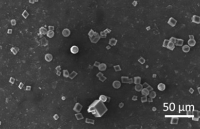
As discussed, calcium carbonate was precipitated by combination of equal volumes of equimolar solutions of CaCl2 and Na2CO3 in three different ways: in bulk solution, in a continuous flow microfluidic device, and within droplets generated in a microfluidic channel. Precipitation of calcium carbonate in bulk solution was performed by combining equal volumes of equimolar (4 and 8 mM) CaCl2 and Na2CO3 solutions. At both concentrations, vaterite and calcite crystals with an average size of 10 μm were produced. These could be distinguished by their characteristic morphologies, i.e., calcite crystals are rhombohedral while vaterite crystals are spherical and clearly polycrystalline (Figure 2). These polymorph assignments were further confirmed by Raman microscopy of individual particles. Calcite is characterised by peaks at 711 cm−1 (ν4) and 1085 cm−1 (ν1) and vaterite by a doublet peak at 1088 cm−1 (ν1).27 The ratio of calcite to vaterite crystals was approximately 1:1 for all concentrations studied.
Figure 2.
SEM micrograph of CaCO3 particles precipitated in bulk solution by combination of 4 mM CaCl2 and Na2CO3 solutions. A mixture of calcite and vaterite polymorphs is reproducibly obtained in a (approximately) 1:1 ratio with an average crystal size of 9 μm.
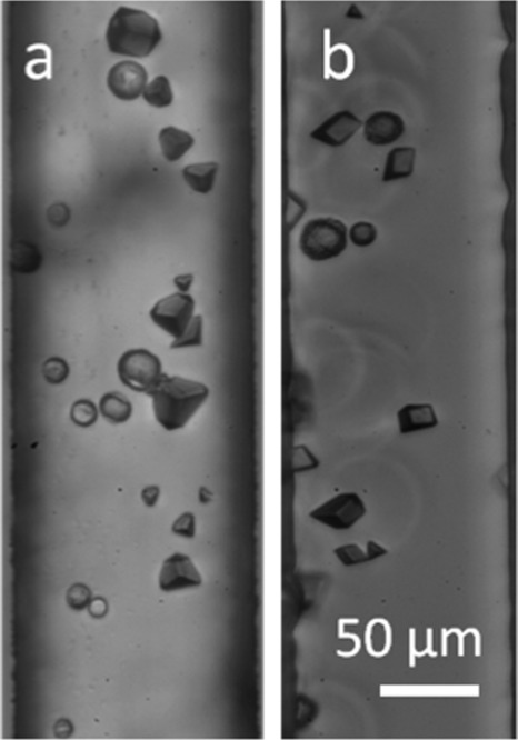
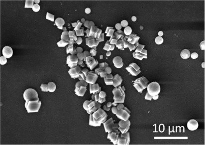
Calcium carbonate was also precipitated in a continuous flow reactor by combination of streams of CaCl2 and Na2CO3 solutions. Mixing of input streams occurs almost entirely via diffusion across the interface between the two laminae, and variation of channel dimensions and the volumetric flow rates of the input streams provide a direct method of controlling the rate of mixing. Unfortunately, the walls of the microchannel impart shear forces on the contained fluid, and under an applied hydrodynamic pressure, a parabolic velocity profile is established over the cross section of the channel, with the fluid velocity being effectively zero at the channel walls and reaching a maximum at the centre of the channel. The reaction mixture that is collected at the channel outlet will therefore comprise an ensemble of volume elements that have spent varying amounts of time on chip, thus compromising control over crystal growth. Reagent solutions of concentration 4 or 8 mM were employed, and both reaction conditions yielded a mixture of rhombohedral, truncated rhombohedral, and spherical particles (Figure 3). The spherical particles were identified by Raman microscopy (data not shown) as vaterite and rhombohedral calcite. The ratio of vaterite to calcite crystals was approximately 1:1 for 4 mM solutions and 7:3 for 8 mM solutions.
Figure 3.
Photomicrographs of CaCO3 particles precipitated in a continuous flow microfluidic device, through combination of CaCl2 and Na2CO3 solutions concentrations of (a) 4 mM and (b) 8 mM. A mixture of rhombohedral, truncated rhombohedral, and spherical particles were obtained with an average size of 8.5 μm. The ratio of vaterite to calcite was approximately 1:1 for 4 mM solutions and approximately 1:1.43 for 8 mM solutions.
While both of the above methods provide limited control over calcium carbonate crystallisation, highly reproducible results were obtained by confining reagents within droplets formed under a segmented-flow regime. This approach utilises two immiscible phases: a dispersed (oil) or discontinuous (aqueous) phase. Importantly, the droplets formed are isolated and encapsulated by the continuous phase, which also wets the channel walls. Each 250 pL volume droplet serves as a compartment for reaction and can be dosed with precisely defined amounts of reagents. Further, since the droplets all move through the microchannel at constant velocities, the timescales and crystallisation environment in each is essentially identical.
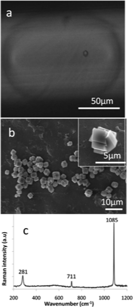
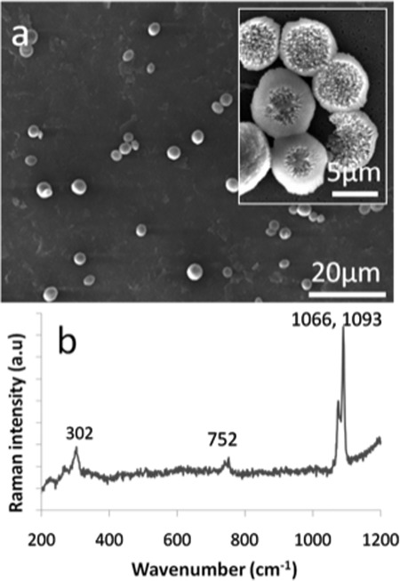
The benefits of using a segmented-flow system were demonstrated by performing experiments in which the concentrations of both the calcium chloride and sodium carbonate streams were varied. As shown in Figure 4a, 250 pL droplets formed by combination of 4 mM CaCl2 and Na2CO3 solutions supported the formation of rhombohedral crystals between 1 and 3 μm in size. On average, each droplet contained between 3 and 5 crystals. It should be noted that only one particle is observed in Figure 4a since the limited depth of field of the optical microscope precluded imaging the entire contents of the droplet in a single image. Isolation of the crystals and examination at higher magnification showed that each comprised inter-grown rhombohedra (Figure 4b), while Raman microscopy of individual crystals confirmed the calcite polymorph through observation of bands at 711 cm−1 (ν4), 1085 cm−1 (ν1), and 281 cm−1 (lattice mode vibrations) (Figure 4c).27 In contrast, when calcium carbonate was precipitated by combination of 8 mM CaCl2 and Na2CO3 solutions within similar sized droplets, only spherical particles 3–4 μm in diameter were produced (Figure 5). The presence of a narrow double peak at 1088 cm−1 (ν1) and a broad peak at 302 cm−1 (corresponding to the translational and rotational lattice modes) confirmed the vaterite polymorph.26 Higher concentrations of input reagents (10 and 12 mM) were also investigated, with both calcite and vaterite polymorphs being. Combined TEM and Raman spectroscopic analysis of the resulting crystals for the 10 mM concentrations indicated that the crystals were approximately 60% calcite with an average size of 4 μm (Figure 6).
Figure 4.
(a) Photomicrograph of an individual droplet formed in the microfluidic device approximately10 s after the start of the reaction. The droplet contents were formed by combination of 4 mM CaCl2 and Na2CO3 solutions, and a single rhombohedral calcite particle can clearly be seen within the droplet. (b) SEM micrograph of CaCO3 particles isolated from microdroplets formed by combination of 4 mM CaCl2 and Na2CO3 solutions. Only rhombohedral crystals between 1 and 2 μm in size were obtained. The inset shows an individual particle at higher magnification. (c) Raman spectrum of one of the crystals shown in (b).
Figure 5.
(a) SEM micrograph of CaCO3 particles precipitated in pL-volume droplets after combination of 8 mM CaCl2 and Na2CO3 solutions. Only spherical particles which were 3–6 μm in diameter were produced. The inset shows a high magnification image of selected particles. (b) The corresponding Raman spectrum of the particles confirming the vaterite polymorph.
Figure 6.
SEM micrograph of calcium carbonate isolated from pL-volume droplets formed by combination of 10 mM CaCl2 and Na2CO3 solutions. The particles obtained were approximately 60% calcite, with an average size of 4 μm.
DISCUSSION
The segmented flow data clearly demonstrate that nondisperse droplets provide extremely well-defined environments for CaCO3 crystallisation reactions. In bulk or continuous flow experiments, a mixture of calcite and vaterite polymorphs was obtained for all solution concentrations studied. In contrast, by confining the reaction mixture in droplets that move at constant linear velocity, a required polymorph could be uniquely selected by tuning the reagents concentrations, i.e., calcite and vaterite were exclusively produced at reagent concentrations of 4 mM and 8 mM, respectively, while a mixture of calcite and vaterite was produced at a concentration of 10 mM. Droplets also support the formation of smaller crystals displaying a narrower size distribution. Calcite crystals precipitated from 4 mM CaCl2/Na2CO3 solutions in droplets, single flow, and bulk solutions have mean sizes of 2, 8.5, and 9 μm, and population standard deviations of 0.24, 0.9, and 1.5, respectively. It is likely that the crystals contained in droplets nucleate over a short time period, and then grow in competition with each other, leading to crystals of near identical size. Indeed, as each droplet has a typical volume of 250 pL, there is a limited pool of reagents which will be rapidly consumed, resulting in termination of crystal growth. Furthermore, most droplets can be expected to be impurity-free such that crystals will nucleate either homogenously or at the solution/oil interface. However, as the surfactant employed to stabilize the droplets is non-ionic (it is a perfluorinated polyether-polyethylene glycol block-copolymer), it would not be anticipated to actively promote nucleation.
In contrast, the bulk solution provides a heterogeneous environment for crystal nucleation and growth, and nucleation will occur over a greater span of times, leading to a wider size distribution of the final crystallites. The continuous flow microfluidic system was also associated with a wide distribution of crystals sizes. This has been observed previously for calcium carbonate21, 22 and is unavoidable due to the residence time distributions associated with continuous-flow operation. Importantly, segmented flow reactions do not suffer from such limitations as droplets do not interact with channel walls and therefore move at a constant linear velocity, eliminating residence time distributions.
That the droplets also enable polymorphic control over calcium carbonate precipitation is fascinating, and suggests that they may provide a unique opportunity for obtaining greater insight into polymorphism under highly controlled reaction conditions. Calcium carbonate precipitates as a number of polymorphs including the three anhydrous crystalline phases, which in order of decreasing stability under ambient conditions are calcite, aragonite and vaterite, and an amorphous calcium carbonate (ACC) phase, which is usually precipitated as a short-lived precursor phase when its saturation has been exceeded.23 There are also two hydrated polymorphs, calcium carbonate monohydrate and hexahydrate, but these are generally only observed at low temperatures. When precipitating calcium carbonate from solution, the most common polymorphs observed are calcite and vaterite, where the metastable vaterite will gradually transform to calcite. Aragonite is uncommon at room temperature due to its high nucleation barrier, and ACC is typically only present as a very short-lived precursor phase.
Although vaterite is metastable with respect to calcite, and is often precipitated along with calcite, a number of approaches have been used to precipitate it as a pure phase. Additives including certain polymers,28, 29, 30 small molecules,31 and the ammonium ion32, 33, 34 can uniquely promote the formation of vaterite, and vaterite has been precipitated in microemulsions of CTAB (cetyl trimethylammonium bromide) and water-in-oil microemulsions of sodium dodecyl sulphate (SDS).35 A microwave-assisted method was applied to produce vaterite with a range of morphologies from water/ethylene glycol mixtures in the presence of the additives CTAB and SDS,36 while stacks of vaterite platelets were produced on precipitation from a viscous solution of hydroxyethyl cellulose (HEC).37 In contrast, it is difficult to obtain pure vaterite in the absence of additives, especially where the initial ion activity product is above the solubility product of ACC and the crystalline polymorphs form on dissolution and reprecipitation of an ACC precursor phase.38 At low/moderate supersaturations, a number of papers have reported that pure vaterite can be produced under very specific reaction conditions. For example, Kralj et al. reported that vaterite alone can be precipitated when [Ca2+] = [CO32−] = 2.5 mM and pH = 9.3 to 9.9.38 Tai et al. state that it is produced at moderate supersaturations between pH 9.0 and 9.5,39 while Han et al. reported the formation of pure vaterite by infusing a mixture of CO2/N2 gases in CaCl2 solution at pH values below 8.34 Vaterite is well-recognised to form as a precursor to calcite at high supersaturations, but transformation to calcite is rapid.40 In contrast, when the ion activity product of the initial supersaturated solution is lower than the solubility of ACC, only vaterite precipitates. These vaterite crystals are free of calcite seeds and are stable in solution for several days.41 These examples clearly demonstrate that, despite being one of the most studied crystal systems, definition of the reaction conditions, which yield specific polymorphs of calcium carbonate, remains poorly defined. This can be at least partly attributed to the challenges associated with carrying out crystallisation experiments under highly reproducible/controlled reaction conditions.39 These are particularly apparent in the calcium carbonate system as the competitive phase precipitation involved is very complex, with ACC precipitating as a precursor phase at all but very low supersaturations, and both calcite and vaterite being produced under a wide range of conditions.42 Further, nucleation is invariably heterogeneous in bulk solution and impurities may affect the nucleation of the different polymorphs to varying extents.
CONCLUSION
This work provides the first description of the use of a segmented-flow microfluidic reactor for studying the precipitation of calcium carbonate. pL-droplets provide extremely well-defined microenvironments in which to perform crystallisation reactions as they are all identical, and due to their small volumes, the majority will be free of the impurities which can dominate crystallisation reactions in bulk solution. The benefit of this is particularly well demonstrated for the calcium carbonate system where the polymorphs precipitated can subtly depend on the reaction conditions. This leads to significant problems in obtaining reproducible data, particularly at low and moderate supersaturations. With extremely high reproducibility, we have shown that combination of 4 mM reagents in 250 pL droplets uniquely yielded calcite, 8 mM reagents only vaterite, and 10 mM reagents a mixture of calcite and vaterite. In contrast, bulk and continuous-flow microfluidic precipitation of calcium carbonate at the same concentrations and residence times yielded mixtures of both calcite and vaterite. Droplet-based crystallisation therefore provides the precise control of crystal nucleation and growth conditions required to fully characterise the polymorphic behaviour of the complex calcium carbonate system. Current work is investigating this in detail.
References
- Ildefonso M., Candoni N., and Veesler S., Cryst. Growth Des. 11, 1527 (2011). 10.1021/cg101431g [DOI] [Google Scholar]
- Dey A., Bomans P. H. H., Muller F. A., Will J., Frederik P. M., de With G., and Sommerdijk N. A. J. M., Nature Mater. 9, 1010 (2010). 10.1038/nmat2900 [DOI] [PubMed] [Google Scholar]
- Pouget E. M., Bomans P. H. H., Goos J., Frederik P. M., de With G., and Sommerdijk N., Science 323, 1455 (2009). 10.1126/science.1169434 [DOI] [PubMed] [Google Scholar]
- Song R. Q. and Colfen H., Adv. Mater. 22, 1301 (2010). 10.1002/adma.200901365 [DOI] [PubMed] [Google Scholar]
- Kashchiev D. and van Rosmalen G. M., Cryst. Res. Technol. 38, 555 (2003). 10.1002/crat.200310070 [DOI] [Google Scholar]
- Laval P., Giroux C., Leng J., and Salmon J. B., J. Cryst. Growth 310, 3121 (2008). 10.1016/j.jcrysgro.2008.03.009 [DOI] [Google Scholar]
- Santesson S. and Nilsson S., Anal. Bioanal. Chem. 378, 1704 (2004). 10.1007/s00216-003-2403-2 [DOI] [PubMed] [Google Scholar]
- Wolf S. E., Muller L., Barrea R., Kampf C. J., Leiterer J., Panne U., Hoffmann T., Emmerling F., and Tremel W., Nanoscale 3, 1158 (2011). 10.1039/c0nr00761g [DOI] [PMC free article] [PubMed] [Google Scholar]
- Chayen N. E., Stewart P. D. S., and Blow D. M., J. Cryst. Growth 122, 176 (1992). 10.1016/0022-0248(92)90241-A [DOI] [Google Scholar]
- Santarsiero B. D., Yegian D. T., Lee C. C., Spraggon G., Gu J., Scheibe D., Uber D. C., Cornell E. W., Nordmeyer R. A., Kolbe W. F., Jin J., Jones A. L., Jaklevic J. M., Schultz P. G., and Stevens R. C., J. Appl. Crystallogr. 35, 278 (2002). 10.1107/S0021889802001474 [DOI] [Google Scholar]
- Grossier R., Hammadi Z., Morin R., Magnaldo A., and Veesler S., Appl. Phys. Lett. 98, 3 (2011). 10.1063/1.3560453.1 [DOI] [PubMed] [Google Scholar]
- Stephens C. J., Kim Y.-Y., Evans S. D., Meldrum F. C., and Christenson H. K., J. Am. Chem. Soc. 133, 5210 (2011). 10.1021/ja200309m [DOI] [PubMed] [Google Scholar]
- Leng J. and Salmon J. B., Lab Chip 9, 24 (2009). 10.1039/b807653g [DOI] [PubMed] [Google Scholar]
- deMello A. J., Nature (London) 422, 394 (2006). 10.1038/nature05062 [DOI] [PubMed] [Google Scholar]
- Solvas X. C. I. and deMello A., Chem. Commun. 47, 1936 (2011). 10.1039/c0cc02474k [DOI] [PubMed] [Google Scholar]
- Li L. and Ismagilov R. F., Annu. Rev. Biophys. 39, 139 (2010). 10.1146/annurev.biophys.050708.133630 [DOI] [PubMed] [Google Scholar]
- Li L., Mustafi D., Fu Q., Tereshko V., Chen D. L. L., Tice J. D., and Ismagilov R. F., Proc. Natl. Acad. Sci. U. S. A. 103, 19243 (2006). 10.1073/pnas.0607502103 [DOI] [PMC free article] [PubMed] [Google Scholar]
- Zheng B., Gerdts C. J., and Ismagilov R. F., Curr. Opin. Struct. Biol. 15, 548 (2005). 10.1016/j.sbi.2005.08.009 [DOI] [PMC free article] [PubMed] [Google Scholar]
- Laval P., Crombez A., and Salmon J. B., Langmuir 25, 1836 (2009). 10.1021/la802695r [DOI] [PubMed] [Google Scholar]
- Laval P., Lisai N., Salmon J. B., and Joanicot M., Lab Chip 7, 829 (2007). 10.1039/b700799j [DOI] [PubMed] [Google Scholar]
- Yin H., Ji B., Dobson, Mosbahi P. S., Glidle A., Gadegaard N., Freer A., Cooper J. M., and Cusack M., Anal. Chem. 81, 473 (2009). 10.1021/ac801980b [DOI] [PubMed] [Google Scholar]
- Ji B. Z., Cusack M., Freer A., Dobson P. S., Gadegaard N., and Yin H. B., Integr. Biol. 2, 528 (2010). 10.1039/c0ib00007h [DOI] [PubMed] [Google Scholar]
- Meldrum F. C., Int. Mater. Rev. 48, 187 (2003). 10.1179/095066003225005836 [DOI] [Google Scholar]
- Stephens C. J., Ladden S. F., Meldrum F. C., and Christenson H. K., Adv. Funct. Mater. 20, 2108 (2010). 10.1002/adfm.201000248 [DOI] [Google Scholar]
- Loste E., Park R. J., Warren J., and Meldrum F. C., Adv. Funct. Mater. 14, 1211 (2004). 10.1002/adfm.v14:12 [DOI] [Google Scholar]
- Xia Y. and Whitesides G. M., Angew. Chem., Int. Ed. Engl. 37, 550 (1998). [DOI] [PubMed] [Google Scholar]
- Dandeu A., Humbert B., Carteret C., Muhr H., Plasari E., and Bossoutrot J.-M., Chem. Eng. Technol. 29, 221 (2006). 10.1002/ceat.v29:2 [DOI] [Google Scholar]
- Xu A. W., Antonietti M., Colfen H., and Fang Y. P., Adv. Funct. Mater. 16, 903 (2006). 10.1002/adfm.v16:7 [DOI] [Google Scholar]
- Didymus J. M., Oliver P., Mann S., Devries A. L., Hauschka P. V., and Westbroek P. J. Chem. Soc., Faraday Trans. 89, 2891 (1993). 10.1039/ft9938902891 [DOI] [Google Scholar]
- Yu Q., Ou H. D., Song R. Q., and Xu A. W., J. Cryst. Growth 286, 178 (2006). 10.1016/j.jcrysgro.2005.09.046 [DOI] [Google Scholar]
- Dupont L., Portemer F., and Figlarz M., J. Mater. Chem. 7, 797 (1997). 10.1039/a607761g [DOI] [Google Scholar]
- Gehrke N., Colfen H., Pinna N., Antonietti M., and Nassif N., Cryst. Growth Des. 5, 1317 (2005). 10.1021/cg050051d [DOI] [Google Scholar]
- Pouget E. M., Bomans P. H. H., Dey A., Frederik P. M., de With G., and Sommerdijk N., J. Am. Chem. Soc. 132, 11560 (2010). 10.1021/ja102439r [DOI] [PubMed] [Google Scholar]
- Han Y. S., Hadiko G., Fuji M., and Takahashi M., J. Cryst. Growth 289, 269 (2006). 10.1016/j.jcrysgro.2005.11.011 [DOI] [Google Scholar]
- Ahmed J., Menaka , and Ganguli A. K., Cryst. Eng. Comm. 11, 927 (2009). 10.1039/b820928f [DOI] [Google Scholar]
- Qi R. J. and Zhu Y. J., J. Phys. Chem. B 110, 8302 (2006). 10.1021/jp060939s [DOI] [PubMed] [Google Scholar]
- Pach L., Hrabe Z., Komarneni S., and Roy R., J. Mater. Res. 5, 2928 (1990). 10.1557/JMR.1990.2928 [DOI] [Google Scholar]
- Kralj D., Brecevic L., and Nielsen A. E., J. Cryst. Growth 104, 793 (1990). 10.1016/0022-0248(90)90104-S [DOI] [Google Scholar]
- Tai C. Y. and Chen F. B., AIChE J. 44, 1790 (1998). 10.1002/aic.v44:8 [DOI] [Google Scholar]
- Rodriguez-Blanco J. D., Shaw S., and Benning L. G., Nanoscale 3, 265 (2011). 10.1039/c0nr00589d [DOI] [PubMed] [Google Scholar]
- Ogino T., Suzuki T., and Sawada K., Geochim. Cosmochim. Acta 51, 2757 (1987). 10.1016/0016-7037(87)90155-4 [DOI] [Google Scholar]
- Vacassy R., Lemaitre J., Hofmann H., and Gerlings J. H., AIChE J. 46, 1241 (2000). 10.1002/aic.v46:6 [DOI] [Google Scholar]


