Abstract
We report an in-depth study of the long-term reproducibility and reliability of droplet dispensing in digital microfluidic devices (DMF). This involved dispensing droplets from a reservoir, measuring the volume of both the droplet and the reservoir droplet and then returning the daughter droplet to the original reservoir. The repetition of this process over the course of several hundred iterations offers, for the first time, a long-term view of droplet dispensing in DMF devices. Results indicate that the ratio between the spacer thickness and the electrode size influences the reliability of droplet dispensing. In addition, when the separation between the plates is large, the volume of the reservoir greatly affects the reproducibility in the volume of the dispensed droplets, creating “reliability regimes.” We conclude that droplet dispensing exhibits superior reliability as inter-plate device spacing is decreased, and the daughter droplet volume is most consistent when the reservoir volume matches that of the reservoir electrode.
INTRODUCTION
Digital microfluidic (DMF) devices, also known as electrowetting-on-dielectric (EWOD) devices, constitute a platform technology for droplet manipulation. In these systems, droplet control is prioritised over the frequency of droplet creation, allowing the manipulation of droplets in highly parallel and independent configurations on a two-dimensional surface.1 This ease of droplet control makes digital microfluidics a versatile technique for the miniaturisation of experimental methodologies and for the automation of chemical and biological processes.
The adaptable nature of droplet manipulation on DMF devices is one of their greatest advantages. There is no need for moving parts or components, which greatly simplifies device design, and it is possible to dispense with the bi-phasic oil systems common in other microfluidic platforms2 (Figure 1). Each droplet can be individually controlled in both space and time and used as a miniaturised reaction vessel. The versatility of digital microfluidic technology is evident from the breadth of reported application areas, which range from proteomics3 and point-of-care diagnostics4 to chemical synthesis,5 textiles with electrowetting capabilities,6 variable focus microlenses,7 and display technologies.8 This breadth also demonstrates the adaptability of DMF devices, since they can be configured to suit a given application. In particular, the geometric layout of the electrodes used for droplet manipulation creates an environment eminently suited for assay-based applications9 and for the performance of sequential sample preparation steps.3, 10
Figure 1.
(a) Pictorial representation of a digital microfluidic device. (b) Side-view of a DMF device and description of the materials used for fabrication. In digital microfluidic devices, electric fields are used to control individual droplets on a planar surface. Digitised droplet actions such as merging, splitting, and movement can be performed in a reconfigurable manner and, therefore, DMF devices are well suited to array-type protocols.
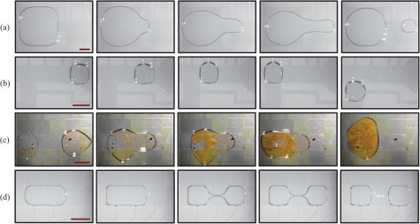
To function as an alternative to macroscale laboratory techniques, DMF devices must be able to perform a basic set of common operations. This “droplet toolkit” consists of droplet dispensing (creating daughter droplets from a larger “reservoir” drop), droplet movement, droplet merging, and droplet splitting (Figure 2). However, these operations must be performed in a controllable, predictable, and reproducible manner.
Figure 2.
Four basic droplet operations on a DMF device. (a) Droplet dispensing is a two-step process. Initially, a finger of liquid is pulled out from the reservoir. A voltage is then applied to both the reservoir and the electrode the liquid finger has reached; effectively pulling the liquid in opposing directions. (b) Droplet movement occurs by turning on an adjacent electrode to the one the droplet is on. (c) A peptide bond formation reaction occurs after droplet merging. Two droplets containing boc-glycine 4-nitrophenyl ester (right hand side droplet) and L-lysine (left hand side droplet), respectively, are brought together and mixed. The yellow side product seen upon formation of the peptide bond is caused by the 4-nitrophenol leaving group. Images for this experiment were adjusted to achieve good contrast and remove colour cast. (d) Droplet splitting is achieved by the step-wise and simultaneous charging of electrodes at opposite sides of a droplet, thereby stretching the droplet in opposite directions until it splits. The scale bars are 1 mm.
Within the droplet toolkit, droplet dispensing and droplet splitting are the most difficult actions to perform due to the large forces needed to break a droplet into two parts. Accordingly, it is necessary to use higher voltages than those needed for droplet movement,11 although this is balanced by the requirement of not exceeding the dielectric-layer-dependent threshold over which contact angle saturation and dielectric layer breakdown occur.12 Gong et al. described in detail the many experimental parameters that affect the volume of droplets after splitting or dispensing. These include the applied voltage and its duration, surface irregularities, dielectric layer breakdown, the dispensing or splitting protocol itself, environmental temperature, and humidity.13 However, in the experiments described in this study, the authors only investigated 12 daughter droplets, as this was the maximum that could be dispensed from a reservoir without re-filling.
Even though the need for dispensing consistent droplet volumes is clear, there is a distinct lack of in-depth characterisation of droplet dispensing or splitting in the literature, especially with regard to long-term device usage. A summary of published studies is presented in Table TABLE I.. It is of note that all but one of these investigations use oil as a filler medium and many use an off-chip pressure source instead of a reservoir and/or capacitance feedback to control droplet volume. Unfortunately, there is little consensus on how best to achieve low levels of variation in daughter droplet volume and there are very limited data available that describe dispensing without an oil filler medium. The work presented herein provides the first detailed study of the reliability of droplet dispensing and assesses its reproducibility in the long term.
TABLE I.
Summary of the literature regarding droplet dispensing in DMF devices.
| Number of dispensed droplets | Volume variation | Off-chip pressure source? | Feedback control? | Oil? | Dielectric layer | Comments |
|---|---|---|---|---|---|---|
| NDP | <3% | No | No | Yes | Parylene | No experimental details provided15 |
| 42 | 13% | No | No | Yes | Parylene | Devices were construced using multi-layer PCB and the reservoir was surrounded by a retaining wall and had two electrode areas, to increase the backpressure on the droplet when dispensing. In addition, an external pump with a three-way valve was used to dispense droplets. The volume variation of the dispensed droplets was only under 10% when also using feedback control16 |
| 79 | 12% | Yes | No | |||
| 42 | 5-6% | Yes | Yes | |||
| 48 | 0.4% | No | No | Yes | Si3N4 | The reservoir was walled-in and had an extra electrode within; increasing the pressure from the reservoir when dispensing17 |
| NDP | 0.2–4% | Yes | No | Yes | Si3N4 | The reservoir was walled-in and had an extra electrode within, increasing the pressure from the reservoir when dispensing18 |
| 12 | 1 or 5% | No | See comments | Yes | Parylene | Multilayer PCB electrondes were used to avoid problems with the deformation of droplets due to contact lines on the same plane of the device. Volume variation was 1% with feedback control and 5% without; however only 12 droplets were measured in each case, as this was the maximum that could be dispensed from a reservoir without re-filling13 |
| NDP | ∼1–3% | No | No | No | Parylene | Volume variation is cited as an estimate and no experimental details were provided3 |
EXPERIMENTAL METHODOLOGY
Device fabrication was performed in a Class 10 000 cleanroom. Indium tin oxide (ITO) covered soda lime glass (Diamond Coatings Limited, Halesowen, UK) was used as the substrate for all devices, with the ITO coating having a resistance of 20 Ohms/sq. Teflon-AF 1600 was purchased under license from DuPont (Wilmington, Delaware, USA). All other chemicals were purchased from Sigma-Aldrich unless otherwise stated.
Electrodes were patterned using conventional lithographic techniques. Briefly, AZ 1512HS positive photoresist (MicroChemicals, Ulm, Germany) was spin-coated onto the substrates (500 rpm for 5 s and 4000 rpm for 30 s), which were then soft-baked at 90 °C for 2 min. Coated substrates were exposed to UV radiation (20 mW/cm2) for 4 s through a bright-field mask (emulsion on polyester film, Micro Lithography Services, Southend-on-Sea, UK) designed in AUTOCAD 2006 (Autodesk, San Rafael, CA). The pattern was then developed using a 3:8 solution of AZ 400K (MicroChemicals, Ulm, Germany) in de-ionized (DI) water. After dehydrating at 90 °C for 2 min, the ITO was etched in a 4:2:1 (v/v/v) solution of HCl, H2SO4, and HNO3 for 20–25 s. The remaining photoresist was then removed with acetone.
Dielectric layer deposition was achieved by spin-coating SU8-2 (MicroChemicals, Ulm, Germany) onto the substrate with the patterned electrodes (500 rpm for 5 s and 3000 rpm for 30 s). Two 60 s post-bakes were necessary at 65 °C and 95 °C, respectively. After removing the SU8 from the contact pads with acetone, the layer was exposed to UV light (20 mW/cm2) for 5 s. Finally, devices were baked at 95 °C for 3 min and at 160 °C for 10 min.
Hydrophobic layer deposition was performed on both plates of the device by spin-coating Teflon-AF (pre-filtered through a 0.2 μm nitrocellulose membrane) onto the devices (500 rpm for 5 s and 1000 rpm for 60 s). Devices were then baked at 160 °C for 10 min and assembled using a 120 μm spacer (SecureSeal, Electron Microscopy Sciences, Hatfield, Pennsylvania) or 76 μm double-sided sticky tape (137 Tape, 3M, Bracknell, UK). Layer thickness and roughness measurements were performed using a stylus profilometer (Dektak 6M, Veeco). The final devices had layers with a thickness of 2 μm and 80 nm for SU8 and Teflon, respectively.
To create a system capable of automated droplet actuation, a voltage switcher was custom-built. This consisted of a Teflon casing with a set of 30 sprung pins (L-Spring, PC7BS, Coda Systems, Halstead, UK) to hold the device in place and provide contact with the contact pads of the patterned plate of the device. A crocodile clip provided voltage to the ground electrode. Individual printed circuit board (PCB) circuits provided a voltage between each pin and the common ground electrode. Relays were used to rapidly switch the voltage from pin to pin and hence to different electrodes in the device. The relays turned on in 1 ms and off in 500 μs, defining the maximum switching speed between electrodes. Voltage was provided by a function generator (Thurlby Thandar TTi TG1010 Programmable 10 MHz Direct Digital Synthesis function generator) set to output x Vrms at 10 kHz. This was then amplified by an AC power amplifier (LPA 400A, Newtons4th Ltd, Loughborough, UK) and the voltage switcher processed the output. Automated droplet movement was achieved by successive electrode activation using a custom-made LABVIEW program to control the voltage switcher.
A stereoscope (E-ZOOM 6V, Edmund Optics Ltd, York, UK), a digital still image camera with video capability (Dragonfly Express Colour Camera, Point Grey Research Inc, Vancouver, Canada) and a cold light source (KL 200, VWR International, Lutterworth, UK) were used for device and droplet imaging and recording. VIRTUALDUB (Freeware, A. Lee, version 1.8.6) and IMAGEJ (Freeware, W. Rasband, NIH, version 1.43u) were used for video and image post-processing.
DROPLET VOLUME CALCULATIONS
Droplet volume calculations are based on the post-experimental processing of images taken through the device lid and are, therefore, influenced by the errors inherent in this method. Interestingly, it is noted that in almost all published DMF research, the exact method of volume calculation is not stated and related errors are ignored. Currently, there is no robust methodology for droplet volume calculations and as such there is a lack of reliability in the droplet volumes quoted in the literature. Accordingly, we present a reliable method for the calculation of droplet volumes in DMF devices.
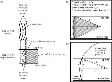
Detailed, step-by-step methodologies for droplet volume calculations and error analysis are provided in the supplementary information (SI)19 for this paper. In brief, the droplet volume was calculated by separating the droplet into two shapes: the inner droplet and the curved boundary region (Figure 3). The inner droplet volume corresponds to the area of the droplet that is full-height within the device. The calculation uses the droplet boundary line observed in the photographic images and the pixel width to determine the full-height boundary of the droplet. The volume of the curved boundary region takes into account the curve of the droplet boundary profile, based on the measured contact angle of DI water on Teflon. The error analysis for this calculation accounts for errors in droplet boundary calculations and image pixilation errors. From these calculations, it is clear that the imaging process can affect droplet volume calculations. To minimise errors, a high-resolution camera should be used to achieve a lower pixelation error and the lighting should be adjusted to minimise the shadowing effects on the droplet (thus reducing boundary errors). In addition, the method of calculating the droplet volume should be adjusted to account for these errors, as detailed in the SI.19
Figure 3.
(a) Schematic of both the plan and side-view of a droplet. The observed boundary area is divided by two to find the area inside the centre line. Half the calculated boundary area is then subtracted to find the area for which the droplet is full-height (the inner droplet area). This is multiplied by the spacer thickness to get the volume of the full-height section. The volume of the curved boundary region is then added. Calculations used to find (b) the cross-sectional area of the curved boundary region and (c) the predicted droplet boundary width.
DROPLET DISPENSING
An experiment was designed to investigate the variation in volume of dispensed droplets and the long-term reliability of droplet dispensing. Dispensing is a two-step process. Initially, a finger of liquid is pulled out from the reservoir (Figure 2a). A voltage is then applied to both the reservoir and the last electrode the liquid finger has reached, effectively pulling the liquid in opposing directions.
The entire experiment consisted of the repetitive dispensing of droplets from a reservoir. The actuation sequence, voltage, and signal duration were kept constant within each experiment. A droplet was dispensed from the reservoir and a photograph was taken from above, the droplet volume was calculated (with an analysis of statistical errors) and the droplet was then returned to the reservoir. These steps were repeated until it was not possible to dispense any more droplets on the device. Throughout these studies, dispensing was defined as a “success” if the dispensing protocol produced a daughter droplet. This concept is used as measure of device performance and to be able to compare droplet dispensing between different devices.
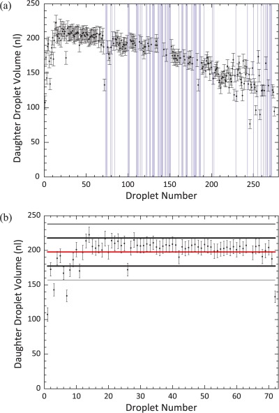
Results in Figure 4a illustrate how the droplet area varies as a function of the number of dispensing operations for a device with a 120 μm spacer. Here, dispensing was attempted 275 times until it became impossible to do so because droplets became stuck to the device surfaces. The experiment lasted for 162 min and the overall success rate in dispensing was 75% (207 droplets). However, it is noted that there is an initial period where it is possible to dispense droplets with 100% success (Figure 4b). Within this droplet subset, there is a large variation in volume for the initial 14 daughter droplets. This can be explained by realizing that the size of the reservoir is initially larger than the electrode it sits on. Once the volume of the reservoir matches that of the reservoir electrode, the volume of the daughter droplets becomes uniform. After this initial period (when dispensing occurs with 100% success), the droplet dispensing protocol regularly fails to produce a daughter droplet, with a concurrent increase in the lack of reproducibility of the daughter droplet volume. This suggests that there is a fundamental change occurring in the device that affects the delicate balance of factors required for dispensing. Since all the operational parameters for the device remain constant throughout, it is likely that this is caused either by degradation of the dielectric layer (not measured quantitatively in this study) and initiation of contact angle saturation, or by the decreasing volume of the reservoir.
Figure 4.
(a) The variation in the volume of dispensed droplets over the device lifetime. A droplet was dispensed from a 2 μl reservoir, its volume was measured, and it was then returned to the reservoir. This process was repeated 275 times. Vertical purple lines have been inserted where the dispensing protocol failed and no daughter droplet was formed. A voltage of 90.0 VAC at 10 kHz was used and electrodes were turned on for 0.5 s. A 120 μm spacer was used in the device. Droplet volume is plotted with respect to droplet number rather than time since dispensing events, although regular, were not equally spaced. (b) The variation in the volume of the first 72 droplets dispensed. The success rate of dispensing was 100%. The red line denotes the mean droplet volume and the thick and thin black lines denote the first and second standard deviation from the mean, respectively. 86% of droplets were within 1 standard deviation of the mean, with a volume variation of 10%.
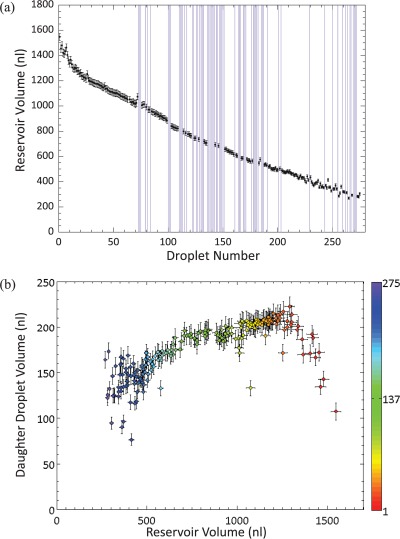
To test the latter hypothesis, the volume of the reservoir was calculated and plotted as a function of time, to show the effect of evaporation (Figure 5a), and versus the volume of the daughter droplet to investigate whether the reservoir volume affects the volume of the dispensed droplet (droplets 1–72, Figure 5b). The latter plot shows that there is a general correlation between the size of the reservoir and the size of the daughter droplet, which becomes more pronounced as the reservoir volume decreases. The scatter in the data at high reservoir volumes (over ∼1300 nl) corresponds to the initial section of droplet dispensing discussed previously, where the reservoir is larger than the reservoir electrode. This may be of particular importance in experiments where an initial reservoir is placed on the device and not re-filled as it is used up. Since the size of the reservoir decreases after each droplet is dispensed, this may lead to a lack of consistency in the volume of daughter droplets.
Figure 5.
(a) Variation in the volume of the reservoir droplet as a function of time. The volume measured represents the volume of the reservoir after a daughter droplet has been dispensed. The reservoir volume is initially 2 μl, but as the experiment progresses fluid from the reservoir evaporates. Vertical purple lines denote a failure to dispense. (b) The effect of the reservoir volume on the volume of the dispensed droplets. The colour scale represents the droplet number, with red being the first daughter droplet dispensed and purple being the last.
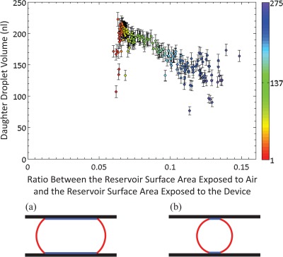
Finally, the daughter droplet volume as a function of the ratio between the surface area of the reservoir droplet exposed to air and the surface area of the reservoir droplet in contact with the hydrophobic device surface was investigated (Figure 6). The ratio between the droplet surface area exposed to air and to the device surface is used as a measure of the energy of the droplet. At low ratios, the reservoir is in a high-energy state due to the large proportion of its surface that is in contact with the device. At high ratios, the reservoir volume is smaller, minimising the surface area of the droplet that is exposed to the device surface. Therefore, the reservoir sits in a lower energy configuration and adopts a more spherical shape. There is a correlation between the inherent energy of the reservoir and the volume and ease of dispensing of the daughter droplet. At low ratios (high energy reservoir state), droplet dispensing is relatively easy since it is energetically favourable for the reservoir to produce a daughter droplet (as explained above, the initial scatter in this graph is due to the mismatch in the size of the reservoir with respect to the area of the reservoir electrode). At high ratios, where the reservoir is small and more spherical in shape, droplet dispensing becomes harder as it is less energetically favourable. Hence, towards the end of multiple experiments, the daughter droplets are small and there is a large variation in their volumes. This experiment was repeated with a thinner spacer (76 μm) to investigate the effect of decreasing the spacing between the plates (and hence increasing the force on the droplet) on the volume variation (CV) of the dispensed droplets. Dispensing was attempted 330 times over the course of 141 min, with a 100% success rate overall (data not shown). Moreover, there is a lower volume variation for the initial part of the experiment when using a thinner spacing; the volume variation being only 6% for the first 160 droplets.
Figure 6.
Daughter droplet volume plotted as a function of the ratio between the exposed surface area of the reservoir and the area of the reservoir in contact with the hydrophobic device surface. The exposed to contact surface areas ratio is used as a measure of the energy of the droplet. At high ratios, the reservoir sits in a lower energy configuration and, therefore, adopts a more spherical shape. Hence, droplet dispensing is harder and daughter droplets are smaller. The colour scale represents the droplet number, with red being the first daughter droplet dispensed and purple being the last. (a) and (b) show the high and low energy configurations of the reservoir, respectively. The red lines denote the surface of the droplet that is exposed and the blue lines denote the surface of the droplet that is in contact with the device. To calculate the surface area of the reservoir that is exposed to air, the length the curved boundary region of the reservoir is first determined. This is the arc segment that encloses A2 in Figure 3b (length = 2 * γ * (π/180) * R). Secondly, the reservoir perimeter is calculated by dividing the single pixel area by the pixel size. The reservoir surface area exposed to air is calculated by multiplying the length of the curved boundary region by the reservoir perimeter.
DISCUSSION
To our knowledge, this is the first rigorous investigation of long-term droplet dispensing behaviour in DMF devices and as such highlights previously unreported phenomena. It has been determined that there are favourable and unfavourable regimes for droplet dispensing, which are amplified as the separation between the plates of the device increases. For situations with a larger spacer, it is noticeable that when the reservoir size is larger than the size of the electrode below it, droplet dispensing produces droplets with a large variation in their volume. This is then followed by a regime where dispensing is predictable and volume variation is low. However, as the experiment progresses, there is a concurrent decrease in the reservoir volume which affects the volume of the daughter droplets. There is also an increase in the failure rate in the dispensing protocol, which is probably an indication of the onset of dielectric layer breakdown.14 Finally, when the reservoir droplet becomes small in size, droplet dispensing becomes an unfavourable action, and hence dispensing becomes somewhat chaotic. An important conclusion that can be determined from these data is that, for the long-term creation of daughter droplets of predictable and regular volume, it is necessary to re-fill the on-chip reservoir as it is depleted. The same experiment performed with a 76 μm spacer showed improved reliability and superior control over the daughter droplet volume, which is useful from an experimental perspective since the benefits accrued from microfluidic systems apply on droplets within this size regime. In most published applications for DMF devices, droplet volume is not investigated in detail, and the reservoir is not re-filled as it is used. Hence, it is not possible to know the exact concentration of reagents used in these experiments and the effect this may have on the assays or syntheses they perform.
Achieving droplet dispensing with very low volume variation depends upon a multitude of factors, only one of which is dielectric layer robustness. Other dielectric layers could cause more predictable inter-device droplet response and delay the onset of dielectric layer breakdown; hence providing better long-term statistics. Most of the published work on droplet dispensing has been performed on devices with Parylene, which is a better dielectric layer than SU8, yet the statistics for volume variation presented here are in line with data provided in the literature (see Table TABLE I.). It is important to note that published experiments are much shorter in duration (tens of droplets rather than hundreds) and, therefore, do not provide long-term analysis of droplet dispensing.3, 13, 15, 16, 17, 18 Comparing the studies presented here to those in Table TABLE I., it is clear that introducing feedback control13, 16 and off-chip pressure sources16, 18 greatly affects droplet dispensing. Most previous work makes use of these and other “aids to dispensing” (such as walls around the reservoir17, 18 and double reservoir electrodes to increase backpressure16). This, however, further complicates device fabrication and increases the need for complicated electronics, off-chip reservoirs, and walls around the reservoirs, significantly affecting the inherent versatility of DMF devices and their use as a stand-alone platform. From an experimental perspective, more reliable dielectric layers should postpone the onset of dielectric layer breakdown, but it does not seem to affect the volume variation of the daughter droplets before this point. As future work, we propose that performing these experiments on devices with different dielectric layers and devices with different aids to droplet dispensing will create a clearer picture of the factors that affect droplet dispensing on DMF devices and will hence further investigate the reliability of DMF devices for droplet operations.
ACKNOWLEDGMENTS
The authors would like to thank Dr Robert Wootton and Ralph Evins for helpful discussions and Stephen Atkins for building the voltage switcher.
References
- Jebrail M. J., Ng A. H. C., Rai V., Hili R., Yudin A. K., and Wheeler A. R., Angew. Chem., Int. Ed. 49, 8625 (2010). 10.1002/anie.201001604 [DOI] [PubMed] [Google Scholar]
- Casadevall i Solvas X. and deMello A., Chem. Commun. 47, 1936 (2011). 10.1039/c0cc02474k [DOI] [PubMed] [Google Scholar]
- Luk V. N. and Wheeler A. R., Anal. Chem. 81, 4524 (2009). 10.1021/ac900522a [DOI] [PubMed] [Google Scholar]
- Mousa N. A., Jebrail M. J., Yang H., Abdelgawad M., Metalnikov P., Chen J., Wheeler A. R., and Casper R. F., Sci. Transl. Med. 1, 1ra2 (2009). 10.1126/scitranslmed.3000105 [DOI] [PubMed] [Google Scholar]
- Marchand G., Dubois P., Delattre C., Vinet F., Blanchard-Desce M., and Vaultier M., Anal. Chem. 80, 6051 (2008). 10.1021/ac800855u [DOI] [PubMed] [Google Scholar]
- Bhat K., Heikenfeld J., Agarwal M., Lvov Y., and Varahramyan K., Appl. Phys. Lett. 91, 024103 (2007). 10.1063/1.2753750 [DOI] [Google Scholar]
- Seo S. W., Han S., Seo J. H., Kim Y. M., Kang M. S., Min N. K., Choi W. B., and Sung M. Y., Jpn. J. Appl. Phys. 48, 052404 (2009). 10.1143/JJAP.48.052404 [DOI] [Google Scholar]
- Heikenfeld J., Zhou K., Kreit E., Raj B., Yang S., Sun B., Milarcik A., Clapp L., and Schwartz R., Nat. Photonics 3, 292 (2009). 10.1038/nphoton.2009.68 [DOI] [Google Scholar]
- Miller E. M. and Wheeler A. R., Anal. Chem. 80, 1614 (2008). 10.1021/ac702269d [DOI] [PubMed] [Google Scholar]
- Nelson W. C., Peng I., Lee G.-A., Loo J. A., Garrell R. L., and Kim C.-J., Anal. Chem. 82, 9932 (2010). 10.1021/ac101833b [DOI] [PMC free article] [PubMed] [Google Scholar]
- Lin Y.-Y., Evans R. D., Welch E., Hsu B.-N., Madison A. C., and Fair R. B., Sens. Actuators B 150, 465 (2010). 10.1016/j.snb.2010.06.059 [DOI] [PMC free article] [PubMed] [Google Scholar]
- Verheijen H. J. J and Prins M. W. J., Langmuir 15, 6616 (1999). 10.1021/la990548n [DOI] [Google Scholar]
- Gong J. and Kim C.-J., Lab Chip 8, 898 (2008). 10.1039/b717417a [DOI] [PMC free article] [PubMed] [Google Scholar]
- Papathanasiou A. G., Papaioannou A. T., and Boudouvis A. G., J. Appl. Phys. 103, 034901 (2008). 10.1063/1.2837100 [DOI] [Google Scholar]
- Ren H., Srinivasan V., and Fair R. B., Transducers 1, 619 (2003). [Google Scholar]
- Ren H., Fair R. B., and Pollack M. G., Sens. Actuators B 98, 319 (2004). 10.1016/j.snb.2003.09.030 [DOI] [Google Scholar]
- Berthier J., Clementz P., Raccurt O., Jary D., Claustre P., Peponnet C., and Fouillet Y., Sens. Actuators, A 127, 283 (2006). 10.1016/j.sna.2005.09.026 [DOI] [Google Scholar]
- Fouillet Y., Jary D., Chabrol C., Claustre P., and Peponnet C., Microfluid. Nanofluid. 4, 159 (2008). 10.1007/s10404-007-0164-5 [DOI] [Google Scholar]
- See supplementary material at http://dx.doi.org/10.1063/1.3693592 for details of the methodology used to calculate droplet volume and the associated error analysis.


