Abstract
Embryoid body (EB) formation forms an important step in embryonic stem cell differentiation invivo. In murine embryonic stem cell (mESC) cultures EB formation is inhibited by the inclusion of leukaemic inhibitory factor (LIF) in the medium. Assembly of mESCs into aggregates by positive dielectrophoresis (DEP) in high field regions between interdigitated oppositely castellated electrodes was found to initiate EB formation. Embryoid body formation in aggregates formed with DEP occurred at a more rapid rate—in fact faster compared to conventional methods—in medium without LIF. However, EB formation also occurred in medium in which LIF was present when the cells were aggregated with DEP. The optimum characteristic size for the electrodes for EB formation with DEP was found to be 75–100 microns; aggregates smaller than this tended to merge, whilst aggregates larger than this tended to split to form multiple EBs. Experiments with ESCs in which green fluorescent protein (GFP) production was targeted to the mesodermal gene brachyury indicated that differentiation within embryoid bodies of this size may preferentially occur along the mesoderm lineage. As hematopoietic lineages during normal development derive from mesoderm, the finding points to a possible application of DEP formed EBs in the production of blood-based products from ESCs.
Introduction
Embryonic stem cells (ESCs) and induced pluripotent stem cells (iPSCs) hold great promise for cell therapy and regenerative medicine because they can self-renew and have a multilineage differentiation potential.1 Of particular interest is the induction of haematopoietic cells from ESCs or induced iPSCs. Such haematopoietic cells could potentially be used for the large-scale production of blood-based materials, including different types of blood cells.3, 4
One of the steps in the induction of differentiated cells from ESCs or iPSCs is the formation of embryoid bodies (EBs). EBs are 3 dimensional aggregates in which tightly packed stem cells undergo a program of differentiation which has many of the characteristics of early-stage embryogenesis.2 A variety of methods have been developed to promote EB formation, and a recent review of the methods used for the formation of EBs from ESCs has been given by Bratt-Leal et al.5 The three most important methods for making EBs are culture-based, i.e., liquid suspension culture in dishes,6 culture in methylcellulose semisolid media, and culture in hanging drops.7, 8 Other methods have included the use of micro well plates9, 10, 11, 12, 13, 14 and aggregation and encapsulation in microbeads.15 For the production of large numbers of EBs, stirred-suspension cultures are performed using spinner flasks16 and stirred bioreactors.17, 18
A major disadvantage of current culture-based methods is that they rely on natural aggregation and often provide poor control over EB size and the (initial) cell distribution. EB size can affect fate decisions9, 13, 19 and influence the early differentiation of the different germ layers.22 To obtain more direct control of EB size and uniformity several microscale technologies have been developed.15, 20, 21, 22, 23, 24 These have included the use of microfabricated adhesive stencils22 and non-adhesive polyethylene glycol (PEG) hydrogel microwells of different diameters,15 as well as microprinting techniques.16, 25
An alternative microscale technology that can be used for the formation of cellular aggregates is the use of physical micromanipulation techniques. Such techniques use a physical force to guide cells, individually or in groups, to a predefined location, thus forming an aggregate. Physical manipulation techniques give a high level of control over the initial distribution of the cells and the number of cells. Physical micromanipulation techniques also allow different cell types to be put within the initial aggregates in predetermined positions and numbers. This is particularly important in attempts to induce the differentiation of ESCs or iPSC by coculture with other cells, for example, during the induced differentiation of haematopoietic cells from ESCs and iPSC.26, 27 Physical micromanipulation techniques that have been used to date to make cell aggregates from suspended cells have included optical tweezers,28, 29, 30 ultrasound,31, 32 magnetic,33 electrical,34, 35, 36, 37, 38, 39 and flow-based techniques.40, 41, 42 Of those, electrical techniques are some of the most versatile.43, 44 Advantages include the fact that electrical forces are universal and can be used for living and non-living material. They can work at both long and short distance; be repulsive as well as attractive. Control of electric fields and their connection to computer devices is straightforward, and electrodes can be used both for exerting electric fields as well as measuring electrodes. Both DC and AC fields can be used, and when AC fields are used, the frequency dependence of the polarizability of the particles can bring a measure of selectivity. The application of DC or low-frequency electric fields can generate high electric field strengths across the cell membrane, which can adversely affect cell viability.45 The electric field strength generated across the cell membrane is significantly reduced at AC frequencies45, 46 higher than 1 MHz.
One of the AC electrokinetic techniques used for the manipulation of cells is dielectrophoresis (DEP). DEP is the induced movement of particles in non-uniform electric fields.47, 48, 49 Both positive DEP (particle movement towards areas of high field strength) and negative DEP (particle movement towards areas of low field strength) are possible, depending on the polarizability of the particle relative to that of the surrounding medium.50 First described47 by Pohl in the 1950 s, the DEP method has since found a plethora of applications in particle manipulation, characterization, and separation.47, 48, 49, 51 Many of these are in the biomedical area. DEP forces on cells are particularly strong as the membrane around cells and the interfacial polarization processes across them induce particularly high dipole moments in the cells. Dispersions that occur in the interfacial polarization processes make the DEP spectrum in the frequency range 10 kHz–100 MHz highly frequency dependent, and most experiments are done in this frequency range. Study of this frequency dependence can give important information about the properties of the cells,47, 48, 49 including stem cells.52 The application of DEP in the characterization of stem cells has recently been reviewed.53 One of the attractions of DEP is also that it is able to manipulate and sort cells with the use of biochemical labels or other bioengineered tags and without contact with surfaces.51
Although the electric fields used during the DEP process can affect cell viability,54 by keeping the electric field across the cell membrane well below the strength above which membrane breakdown occurs the viability of the cells during an experiment can be maintained,45, 46 especially if the exposure time to the electric fields is short and if high frequencies are used.45
One of the applications of DEP is patterning of cells and the formation of cell constructs. This has included the construction of three dimensional cell aggregates.34, 35, 36, 37, 38, 39, 55, 56 Potential applications of such cell arrays and aggregates created with DEP have included biofilms for biocatalysis and bioremediation,57 cell-based biosensors,46 models for developmental or disease studies,58 and engineered tissues for regenerative medicine.34, 35, 36, 37, 38, 39 Applications of DEP in tissue engineering have recently been reviewed.43, 44 In this study we describe the application of positive DEP in the construction of embryoid bodies. The study forms part of a research programme aimed at the development of artificial stem cell microenvironments.56
MATERIALS AND METHODS
Cells
ESC lines used were murine ESC line 7a, in which green fluorescent protein (GFP) expression is controlled by a constitutive promoter,59 and Brachyury ESC line Bry-ESC,60 in which GFP expression was under the control of the mesoderm-specific Bry promoter. Both cell lines were grown as described previously.61, 62 Briefly, 106 ESCs were plated onto T25 culture flasks coated with 0.1% gelatin in 10 ml GMEM medium supplemented with 10% fetal calf serum (FCS), 1% MEM non essential amino acids (Invitrogen), 1 μg ml−1 β-mercaptoethanol and 10 μg ml−1 sodium pyruvate, with 100 U/ml added leukaemia inhibitory factor (LIF). LIF inhibits differentiation, and the presence of LIF, therefore, kept the ESCs in an undifferentiated state. Passaging was performed every 48 h when the cells reached a confluency of 80%. For dielectrophoretic experiments the cells were washed with 300 mM D-sorbitol in deionised water twice to reduce the medium conductivity and finally resuspended in 300 mM D-sorbitol solution (σ = 4.7 × 10⁻⁴ S m−1) for patterning with positive DEP.
Dielectrophoresis
A dielectrophoresis setup was used as described previously.38, 39, 55, 56 The system was based around glass slides with ITO microelectrodes of the interdigitated, oppositely castellated design with characteristic sizes between 25 and 250 μm, made using photolithography. Although available, electrodes with a characteristic size of 25 μm were not used in the experiments. In some experiments, to minimize cell adhesion to the surface, the glass slides with ITO microelectrodes were incubated for 48 h in 1-hexadecanethiol (Sigma-Aldrich). The slides were washed thoroughly with deionized water and wiped carefully with water soaked tissue paper. The slides were checked for defects and the presence of any particles prior to use.
A chamber was constructed on top of each slide from two strips of insulating tape and a microscopic slide coverslip. The chamber covered a single microelectrode region at a time. The height of the chamber was 560 μm, its length 20 mm, and its width 5 mm. Following sterilization by autoclaving the chamber was filled with the low conductivity 300 mM D-sorbitol solution with a pipette. Electric fields were then generated between the microelectrodes by applying a signal with a frequency of 1 MHz with a Thurlby-Thandar TG120 function generator to selected microelectrodes. Cells were introduced with a pipette into the chamber and attracted to the high field regions between the electrodes. Fresh sorbitol solution was passed through the chamber by adding sorbitol solution on one side of the chamber and removing it from the other. This made it possible to redistribute the cells over the electrodes, remove non-attracted cells, and maintain a low conductivity in the chamber. 1 MHz was chosen because at this frequency, in the very low conductivity sorbitol medium, the cells would experience a strong positive DEP force. As shown previously,38 a voltage of 10 Vpk-pk gave an electric field strength that was strong enough to hold the cells between electrodes with a characteristic size of 25–100 μm, without strongly affecting cell viability. For electrodes with a characteristic size between 125 and 250 μm larger electric field strengths were needed to hold cells against any hydrodynamic forces created during the assembly process. A voltage of 20 Vpk-pk was experimentally found to be satisfactory.
To immobilize the cells in the aggregates, as a first step the electric field was maintained for a further 10–15 min. This caused the cells to stick to each other by non-specific adhesive forces.38 Following this, the sorbitol solution in the chamber was replaced with a 25% BD PuramatrixTM solution (3 DM Inc, Cambridge, USA).63 Puramatrix is a fully synthetic peptide and contains no detectable growth factors or cytokines. The Puramatrix solution (made by mixing the Puramatrix precursor solution supplied by the distributor with 300 mM sorbitol solution) was introduced into the chamber by carefully adding the Puramatrix solution at one end of the chamber using a pipette and removing sorbitol solution from the other end with another pipette. Once the chamber had been filled with Puramatrix solution the electric field was switched off and GMEM growth medium was added at the edge of the chamber to initiate gel formation. Gel formation took approximately 10 min from the introduction of growth medium. The chamber was then placed in an incubator at 37 °C, 5% CO2, and images were taken of the aggregates over a period of 24–72 h.
RESULTS AND DISCUSSION
Aggregate formation of 7a murine ESCs with DEP
Aggregates were made of 7a GFP-expressing ESCs at microelectrodes of different sizes ranging from 50 to 250 μm and immobilized in 25% Puramatrix. Following this, the cells were incubated in GMEM growth medium without LIF to initiate differentiation. Previous experiments within our group on stem cell microniches had used single ESCs,56 and EB formation had not been attempted. Patterning of ESCs with DEP has also been reported by other groups, but only monolayers had been formed.64 All human and murine ES cells are known to need aggregation to initiate EB formation.7, 65 The aggregates formed here were all 3-dimensional and many cell layers high.39
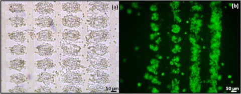
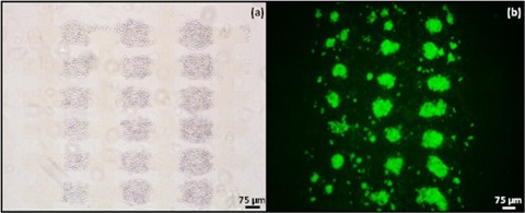
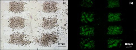
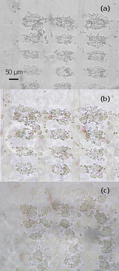
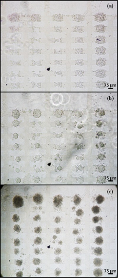
Figures 123 show brightfield images of aggregates of ESCs immediately after they had been formed, and green fluorescent images of the aggregates after 24 h. 7a ESCs produce GFP constitutively, and GFP production was therefore used only to make tracking of cells easier. In 7a ESCs GFP production is not a measure of differentiation. At all electrodes sizes used the ESCs condensed into embryoid bodies.
Figure 1.
Aggregates of 7a ESCs formed by DEP at 10 Vpk-pk, 1 MHz in the 50 μm microelectrode regions. The aggregates were immobilised in 25% Puramatrix and provided with medium without LIF. (a) Bright field image of aggregates at 0 h. Cells were introduced from right to left, and more cells can be seen to have accumulated in the aggregates at the right hand side than on the left hand side. (b) Green fluorescent image of aggregates after 24 h of incubation. Aggregates can be seen to have merged, especially in regions where there were more cells at the start.
Figure 2.
Aggregates of 7a ESCs formed by DEP at 10 Vpk-pk, 1 MHz in the 75 μm microelectrode regions. The aggregates were immobilised in 25% Puramatrix and provided with GMEM growth medium without LIF. (a) Bright field image of aggregates fromed with DEP at time zero. (b) Green fluorescent image of aggregates after 24 h of incubation. After 24 h most individual aggregates have started to form a single EB.
Figure 3.
Aggregates of 7a ESCs formed by DEP at 20 Vpk-pk, 1 MHz in the 200 μm microelectrode regions. The aggregates were immobilised in 25% Puramatrix and provided with GMEM growth medium without LIF. (a) Aggregates at 0 h. (b) Aggregates after 24 h of incubation. Within the aggregates many small cell clumps/EBs can be seen to have formed.
Figure 1 shows ESC aggregates formed at microelectrodes with a characteristic size of 50 μm. Cells were introduced into the chamber from right to left. This caused more cells to accumulate in each aggregate on the right hand side and less on the left. Figure 1b shows that after 24 h of incubation the cells had started to form EB-like structures. On the right hand side, where large aggregates had formed which were very close to each other, the aggregates had started to merge.
Figure 2 shows cell behavior typical of that of microelectrodes with characteristic sizes of 75 μm. At this electrode size the initial distance between the aggregates of ESCs was slightly larger than between aggregates formed at electrodes with a characteristic size of 50 μm. When the cells initiated EB formation most aggregates formed single EBs, though some secondary EB formation can also be seen. Cell behavior at electrodes with a characteristic size of 100 μm was similar to that at 75 μm electrodes.
At regions above 100 μm the cells within an individual aggregate condensed into several high density regions, causing the aggregates to split. Figure 3 shows aggregates formed at microelectrodes with a characteristic size of 200 μm.
Although no attempt was made to directly measure cell viability, the continued production of GFP and condensation of the ESCs into EBs indicated that the ESCs survived the DEP assembly procedure well. EB formation was also fast. EB formation started within 24 h under the conditions used in our experiments. In established protocols for the induction of EBs in suspension culture technique takes 3–5 days incubation of cells suspended in differentiation medium, whereas the hanging drop method usually requires a 2 day incubation period.66 Accelerated EB formation in engineered aggregated of ESCs has been reported previously,67 a finding which has been confirmed in our experiments.
The optimum initial aggregate size for embryonic body formation appeared to be around 75–100 micron. Too small an aggregate size led to dispersion and merging of adjacent aggregates; too large an aggregate size causes the aggregate to break up into many EBs. The optimum size is similar to that observed in other experiments on EB formation.13
Effect of LIF on EB formation
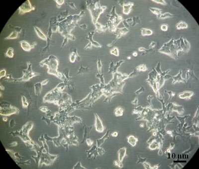
In the previous experiments EB formation was induced by the aggregation of the ESCs with DEP and omission of LIF in the growth medium. To determine whether it was the aggregation of the cells with DEP that induced EB formation or the omission of LIF, a number of control experiments were performed. In the first set of control experiments cells were exposed to the same procedure as the cells which were aggregated with DEP, but electric field exposure was omitted, and no aggregation therefore occurred. When subsequently grown in medium with LIF the cells resumed undifferentiated growth as a monolayer, indicating that the handling of the cells itself, including their temporary suspension in a low conductivity sorbitol solution, did not change the characteristics of the stem cells (see Fig. 4).
Figure 4.
When not aggregated with DEP, and resuspended in medium with LIF, ESCs resumed undifferentiated growth as a monolayer.
In the second set of control experiments the cells were aggregated with DEP and subsequently grown in a medium which contained LIF at the same concentration as normal growth medium (100 U/ml). Under these conditions the cells in the aggregates delayed EB formation and formed irregular EBs (Fig. 5). However, EB formation still occurred, typically within 48 h. These results indicate that the aggregation with DEP is the primary factor that induces EB formation.
Figure 5.
Aggregate development in 25% Puramatrix in presence of LIF. Aggregates were formed with 7a ESCs at interdigitated oppositely castellated microelectrodes with a characteristic size of 50 μm using a 10 Vpk-pk, 10 MHz signal. (a) Aggregates at 0 h, immediate after their formation; (b) Aggregates after 24 h. Significant condensation of the cells in the aggregates has occurred; (c) Aggregates after 48 h, showing the aggregates have condensed further. At electrode sizes larger than 50 μm similar behavior was shown, i.e., delayed EB formation in medium LIF compared to medium without LIF.
It is not known whether the high electric fields used themselves played any role in ESC differentiation. Very low frequency (1 Hz) AC sinusoidal electric fields have been shown to affect stem cell differentiation,66 but the AC fields used in this study were of a much higher frequency (1 MHz). Further experiments would be needed to determine this.
Influence of properties of the electrode surface on the merging of aggregates
Short term experiments (within a 24 h timeframe) indicated that significant exchange of cells occurred between adjacent aggregates when the aggregates were near. Longer term experiments showed63 that migration could also occur over longer distances. Such cell movements are likely to affect EB formation and therefore affect the differentiation of the ESCs that form the EB.
To investigate the role of the electrode surface in the movement of cells between aggregates process, DEP slides were treated with 1-hexadecanethiol. Treatment with 1-hexadecanethiol would make the surface highly hydrophobic and could be expected to prevent cells from adhering to the surface and travelling between aggregates. Figure 6 shows the effect of treating the surface with 1-hexadecanethiol on EB formation. Unlike the experiments in which the surface was left untreated, there was little or no evidence of exchange of cells between EBs, and merging of aggregates did not occur.
Figure 6.
Aggregates of 7a murine ESCs formed by DEP at 10 Vpk-pk, 1 MHz in the 75 μm microelectrode regions, treated with 1-hexadecanethiol. The aggregates were immobilised in 25% Puramatrix and provided with GMEM growth medium without LIF. (a) 0 h (b) 24 h, (c) 48 h.
Differentiation occurs along the mesoderm lineage
Aggregates were made with Bry ESCs in order to investigate whether aggregation by DEP triggers differentiation along the mesoderm lineage. Bry ESCs will only express GFP when the mesoderm programme is initiated. Aggregate size is known to affect the type of cells the ESCs differentiate into.9, 13, 19, 22 Differently sized microelectrodes were therefore used in order to obtain aggregates with different sizes. However, because aggregates formed at electrodes with a characteristic size larger than 125 μm tended to split up into smaller units, no electrodes with a characteristic size larger than 100 μm were used. Green fluorescent and brightfield images were taken of the aggregates with a Leica TCS2 confocal microscope, and the average green intensity in the aggregates was determined using image analysis.
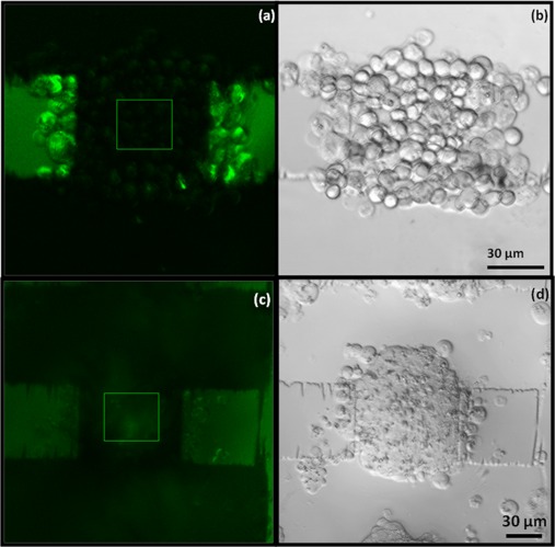
At all electrode sizes (50, 75, and 100 μm) the aggregates formed by DEP condensed into EBs. An example of an aggregate formed with Bry ESCs with DEP and the resultant EB is shown in Fig. 7.
Figure 7.
Aggregate of Bry-GFP ESCs at 75 μm electrode region at zero hours, formed by applying a 1 MHz, 10 Vpk-pk signal to interdigitated oppositely castellated electrodes. The aggregate was immobilized in 25% Puramatrix and incubated with GMEM growth medium without LIF. (a) Green fluorescence image of an aggregate at zero hours showing the region of interest for image analysis. (b) Bright field image of an aggregate at zero hours. (c) Green fluorescent image of an aggregate at 24 h showing the region of interest. (d) Bright field image of an aggregate forming an EB after 24 h.
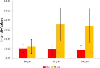
The average intensity values of the green fluorescence in the aggregates in the three electrode regions at 0 and 24 h are shown in Fig. 8. The EBs formed in the 50 μm region showed a negligible increase in green fluorescence whereas the EBs formed in the 75 and 100 μm regions showed significant increases in the intensity values. This indicates that the cells in the 75 and 100 μm regions are differentiating along the mesoderm lineage, but the cells in the 50 μm region are not. This is most likely due to the smaller size of aggregate in the 50 μm region at the start of the experiment.
Figure 8.
Comparative study of the average intensity values in Bry ESC aggregates. Data were plotted at 0 and 24 h for Bry ESC aggregates formed at different microelectrode regions. Also shown are 95% confidence values in the form of error bars.
CONCLUSIONS
We have shown that the attraction of ESCs by positive DEP to high field regions between the castellations of interdigitated oppositely castellated electrodes can induce the formation of EBs. The optimum size for the formation of EBs was 75–100 micron. EB formation in medium without LIF occurred with 24 h. This is significantly faster than EB formation in conventional culture-based methods, which typically takes 2–3 days. Condensation into EB-like aggregates also occurred in the presence of the LIF. This appears to indicate that EB formation is induced simply by the assembly of the ESCs into an aggregate. Experiments with Bry ESCs indicated that the differentiation of the stem cells occurs along the mesoderm lineage. Differentiation along the mesoderm lineage is a first step towards the differentiation towards the haematopoietic lineage. The haematopoietic lineage leads to all types of blood cells. The results therefore not only confirm the utility of DEP in the study of stem cells53, 68, 69 but also indicate a possible role for DEP in the construction of EBs from ESCs for as a first step in the formation of blood-based products.3, 4
ACKNOWLEDGMENTS
We wish to thank the BBSRC for funding and Heriot-Watt University for a James Watt Scholarship for SA. We wish to express our thanks to M. McGowan and Dr. J. Hatfield for the use of SEEE clean rooms at Manchester University for microelectrode manufacture. Our special thanks go to Helen Taylor at Centre for Regenerative Medicine, Edinburgh, for her valuable assistance and advice regarding stem cell culture. We wish to Dr Stephen Euston and Professor Rory Duncan for help and advice on confocal microscopy and image analysis.
References
- Dvash T. and Benvenisty N., Best. Pract. Res. Clin. Obstet. Gynaecol. 18, 929 (2004). 10.1016/j.bpobgyn.2004.06.005 [DOI] [PubMed] [Google Scholar]
- Debailets I., Ziegler U., Groscurth P., and Grassmann M., Exp. Physiol. 85, 645 (2000). 10.1017/S0958067000021047 [DOI] [PubMed] [Google Scholar]
- Lengerke C. and Daley G. Q., Blood Rev. 24, 27 (2010). 10.1016/j.blre.2009.10.001 [DOI] [PMC free article] [PubMed] [Google Scholar]
- Grabel L., J. Cell Biochem. 113, 381 (2012). 10.1002/jcb.23364 [DOI] [PubMed] [Google Scholar]
- Bratt-Leal A. M., Carpenedo R. L., and McDevitt T. C., Biotechnol. Prog. 25, 43 (2009). 10.1002/btpr.139 [DOI] [PMC free article] [PubMed] [Google Scholar]
- Ramirez M. A., Pericuesta E., Fernandez-Gonzalez R., Pintado B., and Gutierrez-Adan A., Int. J. Dev. Biol. 51, 397 (2007). 10.1387/ijdb.062255mr [DOI] [PubMed] [Google Scholar]
- Dang S. M., Kyba M., Perlingerio R., Daley G. Q., and Zandstra P. W., Biotechnol. Bioeng. 78, 442 (2002). 10.1002/bit.10220 [DOI] [PubMed] [Google Scholar]
- Dang S. M., Gerecht-Nir S., Chen J., Itskovitz-Eldor J., and Zandstra P. W., Stem Cells 22, 275 (2004). 10.1634/stemcells.22-3-275 [DOI] [PubMed] [Google Scholar]
- Ezekiel U. R., Electron J. Biotechnol. 10, 328 (2007). 10.2225/vol10-issue2-fulltext-2 [DOI] [Google Scholar]
- Koike M., Kurosawa H., and Amano Y., Cytotechnology 47, 3 (2005). 10.1007/s10616-005-3743-x [DOI] [PMC free article] [PubMed] [Google Scholar]
- Koike M., Sakaki S., Amano Y., and Kurosawa H., J. Biosci. Bioeng. 104, 294 (2007). 10.1263/jbb.104.294 [DOI] [PubMed] [Google Scholar]
- Konno T., Akita K., Kurita K., and Ito Y., J. Biosci. Bioeng. 100, 88 (2005). 10.1263/jbb.100.88 [DOI] [PubMed] [Google Scholar]
- Ng E. S., Davis R. P., Azzola L., Stanley E. G., and Elefanty A. G., Blood 106, 1601 (2005). 10.1182/blood-2005-03-0987 [DOI] [PubMed] [Google Scholar]
- Langer R., Khademhosseini A., Yeh J., Eng G., Karp J., Kaji H., Borenstein J., and Farokhzad O. C., Lab Chip 5, 1380 (2005). 10.1039/b508096g [DOI] [PubMed] [Google Scholar]
- Hwang Y. S., Chung B. G., Ortmann D., Nobuaki H., Moeller H. C., and Khademhosseini A., P.N.A.S. 106, 16978 (2009). 10.1073/pnas.0905550106 [DOI] [PMC free article] [PubMed] [Google Scholar]
- Niebruegge S., Bauwens C. L., Peerani R., Thavandiran N., Masse S., Sevaptisidis E., Nanthakumar K., Woodhouse K., Husain M., Kumacheva E., and Zandstra P. W., Biotechnol. Bioeng. 102, 493 (2009). 10.1002/bit.22065 [DOI] [PubMed] [Google Scholar]
- Kehoe D. E., Lock L. T., Parikh A., and Tzanakakis E. S., Biotechnol. Prog. 24, 1342 (2008). 10.1002/btpr.57 [DOI] [PubMed] [Google Scholar]
- Kehoe D. E., Jing D., Lock L. T., and Tzanakakis E. M., Tissue Eng. Part A 16, 405 (2009). 10.1089/ten.tea.2009.0454 [DOI] [PMC free article] [PubMed] [Google Scholar]
- Leahy A., Xiong J. W., Kuhnert F., and Stuhlmann H., J. Exp. Zool. 284, 67 (1999). [DOI] [PubMed] [Google Scholar]
- Khademhosseini A., Langer R., Borenstein J., and Vacanti J. P., P.N.A.S. 103, 2480 (2006). 10.1073/pnas.0507681102 [DOI] [PMC free article] [PubMed] [Google Scholar]
- Desai J. P., Pillarisetti A., and Brooks A. D., Ann. Rev. Biomed. Eng. 9, 35 (2007). 10.1146/annurev.bioeng.9.060906.151940 [DOI] [PubMed] [Google Scholar]
- Park J., Cho C. H., Parashurama N., Li Y., Berthiaume F., Toner M., Tilles A. W., and Yarmush M. L., Lab Chip 7, 1018 (2007). 10.1039/b704739h [DOI] [PubMed] [Google Scholar]
- Peerani R., Rao B. M., Bauwens C. L., Yin T., Wood G. A., Nagy A., Kumacheva E., and Zandstra P. W., EMBO J. 26, 4744 (2007). 10.1038/sj.emboj.7601896 [DOI] [PMC free article] [PubMed] [Google Scholar]
- Torisawa Y., Chueh B. H., Huh D., Ramamurthy P., Roth T. M., Barald K. F., and Takayama S., Lab Chip 7, 770 (2007). 10.1039/b618439a [DOI] [PubMed] [Google Scholar]
- Xu F., Srdiharan B., Wang S. Q., Gurkan U. A., Syverud B., and Demirci U., Biomicrofluidics 5, 022207 (2011). 10.1063/1.3580752 [DOI] [PMC free article] [PubMed] [Google Scholar]
- Krassowska A., Gordon-Keylock S., Samuel K., Gilchrist D., Dzierzak E., Oostendorp R., Forrester L. M., and Ansell J. D., Exp. Cell Res. 312, 3595 (2006). 10.1016/j.yexcr.2006.08.001 [DOI] [PubMed] [Google Scholar]
- Ledran M. H., Krassowska A., Armstrong L., Dimmick I., Renstro J., Lang R., Yung S., Santibanez-Coref M., Dzierzak E., Stojkovic M., Oostendorp R. A. J., Forrester L. M., and Lako M., Cell Stem Cell 3, 85 (2008). 10.1016/j.stem.2008.06.001 [DOI] [PubMed] [Google Scholar]
- Curtis J. E., Koss B. A., and Grier D. G., Opt. Commun. 207, 169 (2002). 10.1016/S0030-4018(02)01524-9 [DOI] [Google Scholar]
- Odde D. J. and Renn M. J., Biotechnol. Bioeng. 67, 312 (2000). [DOI] [PubMed] [Google Scholar]
- Birkbeck A. L., Flynn R. A., Ozkan M., Song D. Q., Gross M., and Esener S. C., Biomed. Microdev. 5, 47 (2003). 10.1023/A:1024463316562 [DOI] [Google Scholar]
- Haake A. and Dual J., Ultrasonics 42, 75 (2004). 10.1016/j.ultras.2004.02.003 [DOI] [PubMed] [Google Scholar]
- Gherardini L., Cousins C. M., Hawkes J. J., Spengler J., Radel S., Lawler H., Devcic-Kuhar B., and Groschl M., Ultrasound Med. Biol. 31, 261 (2005). 10.1016/j.ultrasmedbio.2004.10.010 [DOI] [PubMed] [Google Scholar]
- Tanase M., Felton E. J., Gray D. S., Hultgren A., Chen C. S., and Reich D. H., Lab Chip 5, 598 (2005). 10.1039/b500243e [DOI] [PubMed] [Google Scholar]
- Albrecht D. R., Tsang V. L., Sah R. L., and Bhatia S. N., Lab Chip 5, 111 (2005). 10.1039/b406953f [DOI] [PubMed] [Google Scholar]
- Albrecht D. R., Underhill G. H., Wassermann T. B., Sah R. L., and Bhatia S. N., Nat. Meth. 3, 369 (2006). 10.1038/nmeth873 [DOI] [PubMed] [Google Scholar]
- Albrecht D. R., Underhill G. H., Mendelson A., and Bhatia S. N., Lab Chip 7, 702 (2007). 10.1039/b701306j [DOI] [PubMed] [Google Scholar]
- Matsue T., Matsumoto N., and Uchida I., Electrochim. Acta 42, 3251 (1997). 10.1016/S0013-4686(97)00175-8 [DOI] [Google Scholar]
- Sebastian A., Buckle A. M., and Markx G. H., Biotechnol. Bioeng. 98, 694 (2007). 10.1002/bit.21416 [DOI] [PubMed] [Google Scholar]
- Sebastian A., Venkatesh A. G., and Markx G. H., Electrophoresis 28, 3821 (2007). 10.1002/elps.200700019 [DOI] [PubMed] [Google Scholar]
- Tan W. and Desai T. A., Biomaterials 25, 1355 (2004). 10.1016/j.biomaterials.2003.08.021 [DOI] [PubMed] [Google Scholar]
- Mironov V., Boland T., Trusk T., Forgacs G., and Markwald R. R., Trends Biotechnol. 21, 157 (2003). 10.1016/S0167-7799(03)00033-7 [DOI] [PubMed] [Google Scholar]
- Mironov V., Visconti R. P., Kasyanov V., Forgacs G., Drake C. J., and Markwald R. R., Biomaterials 30, 2164 (2009). 10.1016/j.biomaterials.2008.12.084 [DOI] [PMC free article] [PubMed] [Google Scholar]
- Markx G. H., Organogenesis 4, 11 (2008). [DOI] [PMC free article] [PubMed] [Google Scholar]
- Markx G. H. and Buckle A. M., “ Tissue engineering: AC electrokinetics,” in Encyclopedia of Biomaterials and Biomedical Engineering, edited by Wnek G. and Bowlin G. (Taylor and Francis, New York, 2005). [Google Scholar]
- Glasser H. and Fuhr G., Bioelectrochem. Bioenerg. 47, 301 (1998). 10.1016/S0302-4598(98)00146-9 [DOI] [Google Scholar]
- Gray D. S., Tan J. L., Voldman J., and Chen C. S., Biosens. Bioelectron. 19, 1765 (2004). 10.1016/j.bios.2004.03.016 [DOI] [PubMed] [Google Scholar]
- Pohl H. A., Dielectrophoresis (Cambridge University Press, Cambridge, 1978). [Google Scholar]
- Morgan H. and Green N. G., AC Electrokinetics: Colloids and Nanoparticles (Research Studies Press, Herts, 2003). [Google Scholar]
- Hughes M. P., Nanoelectromechanics in Engineering and Biology (CRC Press, Boca Raton, 2002). [Google Scholar]
- Pethig R., Huang Y., Wang X. B., and Burt J. P. H., J. Phys. D.: Appl. Phys. 24, 881 (1992). 10.1088/0022-3727/25/5/022 [DOI] [Google Scholar]
- Pethig R., Biomicrofluidics 4, 022811 (2010). 10.1063/1.3456626 [DOI] [PMC free article] [PubMed] [Google Scholar]
- Flanagan L. A., Lu J., Wang L., Marchenko S. A., Joen N. L., and Monuki E. S., Stem Cells 26, 656 (2008). 10.1634/stemcells.2007-0810 [DOI] [PubMed] [Google Scholar]
- Pethig R., Menachery A., Pells S., and De Sousa P., J. Biomed. Biotechnol. 2010, 182581 (2010). 10.1155/2010/182581 [DOI] [PMC free article] [PubMed] [Google Scholar]
- Menachery A. and Pethig R., IEEE Proc. Nanobiotechnol. 152, 145 (2005). 10.1049/ip-nbt:20050010 [DOI] [PubMed] [Google Scholar]
- Venkatesh A. G. and Markx G. H., J. Phys. D: Appl. Phys. 40, 106 (2007). 10.1088/0022-3727/40/1/S15 [DOI] [Google Scholar]
- Markx G. H., Carney L., Littlefair M., Sebastian A., and Buckle A. M., Biomed. Microdev. 11, 143 (2009). 10.1007/s10544-008-9219-y [DOI] [PubMed] [Google Scholar]
- Verduzco-Luque C. E., Alp B., Stephens G. M., and Markx G. H., Biotechnol. Bioeng. 83, 39 (2003). 10.1002/bit.10646 [DOI] [PubMed] [Google Scholar]
- Yusvana R., Headon D. J., and Markx G. H., Biotechnol. Bioeng. 105, 945 (2010). 10.1002/bit.22615 [DOI] [PubMed] [Google Scholar]
- Gilchrist D. S., Ure J., Hook L., and Medvinsky A., Genesis 36(3 ), 168 (2003). 10.1002/gene.10209 [DOI] [PubMed] [Google Scholar]
- Fehling H. J., Lacaud G., Kubo A., Kennedy M., Robertson S., Keller G., and Kouskoff V., Development 130, 4217 (2003). 10.1242/dev.00589 [DOI] [PubMed] [Google Scholar]
- Jackson M., Taylor A. H., Jones E. A., and Forrester L. M., Meth. Mol. Biol. 633, 1 (2010). 10.1007/978-1-59745-019-5_1 [DOI] [PubMed] [Google Scholar]
- Gordon-Keylock S. A. M., Jackson M., Huang C., Samuel K., Axton R. A., Oostendorp R., Taylor A. H., Wilson J. A., and Forrester L. M., Stem Cells and Development 19, 1687 (2010). 10.1089/scd.2009.0467 [DOI] [PMC free article] [PubMed] [Google Scholar]
- See supplementary material at http://dx.doi.org/10.1063/1.3699969 for supporting text and figures.
- Tsutsui H., Yu E., Marquina S., Valamehr B., Wong I., Wu H., and Ho C. M., Ann. Biomed. Eng. 38, 3777 (2010). 10.1007/s10439-010-0108-1 [DOI] [PMC free article] [PubMed] [Google Scholar]
- Itskovitz-Eldor J., Schuldiner M., Karsenti D., Eden A., Yanuka O., Amit M., Soreq H., and Benvenisty N., Mol. Med. 6, 88 (2000). [PMC free article] [PubMed] [Google Scholar]
- McCullen S. D., McQuilling J. P., Grossfeld R. M., Lubischer J. L., Clarke L. I., and Loboa E. G., Tissue Eng. Part C-Meth. 16, 1377 (2010). 10.1089/ten.tec.2009.0751 [DOI] [PMC free article] [PubMed] [Google Scholar]
- Gothard D., Roberts S. J., Shakesheff K. M., and Buttery L. D., Cytotechnology 61, 135 (2009). 10.1007/s10616-010-9255-3 [DOI] [PMC free article] [PubMed] [Google Scholar]
- Wu H. W., Lin C. C., Lee G. B., Biomicrofluidics 5, 013401 (2011). 10.1063/1.3528299 [DOI] [PMC free article] [PubMed] [Google Scholar]
- Toh Y. C., Blogovic K., and Voldman J., Integrative Biol. 2, 305 (2010). 10.1039/c0ib00004c [DOI] [PubMed] [Google Scholar]


