Abstract
A high-performance microfluidic rectifier incorporating a microchannel and a sudden expansion channel is proposed. In the proposed device, a block structure embedded within the expansion channel is used to induce two vortex structures at the end of the microchannel under reverse flow conditions. The vortices reduce the hydraulic diameter of the microchannel and, therefore, increase the flow resistance. The rectification performance of the proposed device is evaluated by both experimentally and numerically. The experimental and numerical values of the rectification performance index (i.e., the diodicity, Di) are found to be 1.54 and 1.76, respectively. Significantly, flow rectification is achieved without the need for moving parts. Thus, the proposed device is ideally suited to the high pressure environment characteristic of most micro-electro-mechanical-systems (MEMS)-based devices. Moreover, the rectification performance of the proposed device is superior to that of existing valveless rectifiers based on Tesla valves, simple nozzle/diffuser structures, or cascaded nozzle/diffuser structures.
INTRODUCTION
Laboratory-on-a-chip (LoC) devices have many applications in the medicine, food, biology, and engineering fields.1, 2, 3, 4, 5, 6, 7, 8 Miniaturized systems have many benefits compared to their large-scale counterparts, including a higher sample throughput, a lower sample and reagent consumption, an improved performance and reliability, and an improved potential for integration with other microchips and detection systems. Many functional microfluidic devices have been developed to perform such diverse tasks as sample pre-treatment and injection, polymerase chain reaction, species mixing, and cell/particle sorting and counting.9, 10, 11, 12, 13, 14, 15, 16 In such devices, the species are typically manipulated using external devices such as pumps, valves, or actuators.17, 18, 19, 20, 21, 22, 23, 24
In many microfluidic devices, microvalves are combined with a micropump in order to achieve uni-directional species flow. In general, microvalves (also referred to as flow rectifiers) fall into three main categories, namely, active, passives, and valveless.25, 26, 27, 28, 29, 30, 31, 32, 33, 34, 35, 36, 37, 38 Of these three types of microvalve, passive and valveless microvalves have no moving parts. As a result, they are ideally suited to the high flow rate and high pressure conditions found in most microfluidic systems. Alternatively, flow induced vortices are also potentially to be the mechanism for flow rectification since unidirectional flow can be produced. Typically, microscale vortices can be induced with ciliary motion of bacteria such as flagella or artificial cilia.39, 40, 41, 42 However, the flow speed and vortics energy for the induced microscale vortices with microorgans are rather small, which did not meet the requirement for high flow rectification applications. Therefore, it is essential to develop a microfludic device to be the flow rectifiers having a simple structure without no moving parts in the microchannel.
Valveless flow rectifiers are commonly realized using either a Tesla valve structure43 or a nozzle/diffuser structure.44, 45 In such rectifiers, uni-directional species flow is achieved by exploiting the difference in the flow resistance in the forward and reverse directions, respectively. For example, in the Tesla valve,46 the flow resistance in the reverse direction is increased relative to that in the forward direction by means of a pinch effect developed by a serpentine side channel. Similarly, in valveless flow rectifiers with a nozzle/diffuser structure, large flow vortices are induced under reverse flow conditions; effectively constraining the species flow to the forward direction only. Although these microflow rectifiers are relatively easy to be manufactured and have good operational reliability, the poor rectification performance could be an issue for practical applications. The reported diodicities for these kinds of microfluidic rectifiers are in the range of Di = 1.1–1.3. Alternatively, Grosiman and Quake47 presented a flow rectifier in which several triangular nozzle/diffuser structures were cascaded in series so as to increase the flow pressure differential in the forward and reverse directions, respectively. It was shown that the device achieved a diodicity of approximately Di = 2 for viscous, non-Newtonian fluids. Nguyen et al.31 also developed a flow rectifier with a cascaded diffuser structure. The results showed that a diodicity of around Di = 1.8 was achieved for viscoelastic fluids such as polyacrylamide. However, the diodicity fell to Di = 1.1 when using pure water as the sample fluid.
This study develops a novel valveless flow rectifier incorporating a micro-flow channel and a sudden expansion channel. In the proposed device, a block structure embedded near the entrance of the expansion channel is used to induce flow vortex structures at the end of the microchannel under reverse flow conditions. As a result, the reverse flow resistance is significantly increased, and thus the flow is effectively constrained to the forward direction only. The flow fields induced within the device are examined for various Reynolds numbers using both experimental and numerical methods. In addition, the hydraulic pressures of the forward and reverse flows are physically measured. Finally, the rectification performance of the proposed flow rectifier is compared with that of other valveless flow rectifiers presented in the literature.
DESIGN AND OPERATING PRINCIPLE
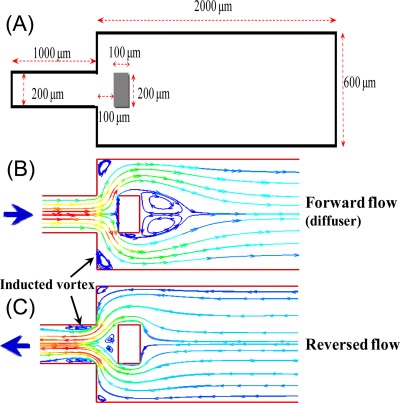
Figure 1 illustrates the dimensions and working principle of the proposed microfluidic rectifier. In order to minimize the flow resistance caused by the microfluidic channel, the lengths of the inlet and outlet channels are set to 1 mm and 2 mm, respectively. In the forward flow condition, vortices are induced in the shoulders of the sudden expansion channel and beside the block structure due to flow separation effects. The vortex structures result in no more than a slight reduction in the effective channel width of the microchannel. As a result, the device acts as a simple diffuser. However, under reverse flow conditions, vortices are induced in front of the block structure and adjacent to the walls at the end of the microchannel. The vortices reduce the effective hydraulic diameter of the flow channel, and thus the flow resistance in the reverse direction is significantly increased.
Figure 1.
(a) Schematic illustration showing dimensions of proposed rectifier with sudden expansion channel. (b) Vortex formation under forward flow conditions. (c) Vortex formation under reverse flow conditions.
MATERIALS AND METHODS
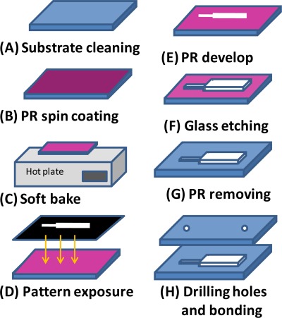
Since the microchannels have to sustain from the high fluid pressure in the microchannel, microchip devices with high mechanical strength, and high bonding strength are required in this study. Accordingly, the microfluidic rectifier developed in this study was fabricated on glass substrates and was sealed using a fusion bonding process. Figure 2 presents an overview of the major steps in the fabrication process. A detailed discussion of the fabrication process can be found in a previous study by the current group.48, 49, 50 Briefly, microchannels with a depth of 36 μm were created using a wet chemical etching process in which patterned glass substrates coated with positive photoresist were immersed in BOE etchant for 40 min. The etched substrates were then sealed with drilled bare glass substrates in a fusion bonding process performed at a temperature of 670 °C for 10 min.
Figure 2.
Overview of microfluidic rectifier fabrication process.
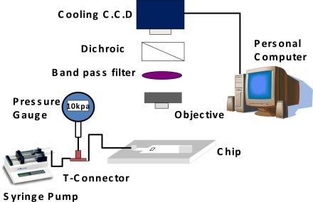
Figure 3 shows the particle image velocimetry (PIV) setup used to evaluate the performance of the microfluidic rectifier. A commercial syringe pump (KDS 200 series, KD scientific, USA) was used to inject sample fluid (DI water) containing fluorescent polystyrene beads (5 μm, Duke scientific, USA) into the inlet via of the rectifier. As the beads flowed through the microchannel and expansion channel of the rectifier, optical images were acquired using a fluorescence microscope (TE2000-U, Nikon, Japan) equipped with a CCD module (1360×1024 pixels, MF cooling CCD, Jenoptik, Germany). The fluid pressure within the microchannel was measured using a pressure meter (DPI 103, GE, USA) connected to the inlet side of the device via a T-junction connector.
Figure 3.
Experimental setup used to evaluate performance of microfluidic rectifier.
Numerical simulations
In modeling, the flow field characteristics within the microchannel and sudden expansion channel, three fundamental assumptions were made: (1) the fluid flow is in steady state conditions, (2) the fluid flow satisfies the continuity equation and Navier–Stokes momentum equation, and (3) the fluid flows in an incompressible manner. The governing equations can therefore be expressed as follows:
| (1) |
| (2) |
where ρ, μ, p, and u are the fluid density, viscosity, pressure, and flow velocity vector (), respectively. Note that the simulations used DI water as the working fluid. Thus, ρ and μ were assigned values of 998 kg/m3 and 0.001 kg/m s, respectively.
Figure 1a presents a schematic illustration of the computational domain used in the present simulations. The computational domain contained approximately 109 870 cells. As shown in the figure, a rectangular block structure with dimensions of 200 μm × 100 μm (width × length) was placed in the sudden expansion channel at a distance of 100 μm downstream of the microchannel exit. Appropriate conditions were specified at the boundary cells of the block to correctly reflect the physical phenomena of the flow field. A plug-flow condition was imposed in the upstream section of the computational domain, while a reference pressure was applied at the outlet of the downstream section. In addition, a symmetric boundary condition was imposed at the horizontal centerline of the microchannel; resulting in a zero-velocity gradient in the direction normal to the boundary. Finally, a no-slip boundary condition was imposed on the channel walls. Note that this condition is reasonable since water flows in hydrophilic channels are known to have negligible slip lengths.
The simulations were performed using FLUENT CFD software. FLUENT is based on the finite volume method, in which the conservation principles are applied to a discrete control volume. In the solution procedure, the governing differential equations were integrated about each control volume to yield a set of algebraic equations, which ensure that all the quantities are conserved on a control volume basis. These algebraic equations were then solved via numerical means in order to obtain the unknown quantities. Due to the discrete nature of the algebraic equations, all the quantities at the center of each control volume were averaged over the control volume. The convection term in each governing equation was discretized spatially using the second order upwind scheme in order to minimize the effects of numerical diffusion. Finally, the pressure and velocity fields were decoupled using the semi-implicit method for pressure-linked equations (SIMPLE).51, 52
RESULTS AND DISCUSSION
The rectification performance of the proposed device was quantified via the diodicity parameter (Di), defined as
| (3) |
where ΔPr is the pressure drop between the inlet and outlet of the microchannels for reverse flow and ΔPf is the pressure drop between the same two points for forward flow. In order to quantitatively evaluate the rectification performance using the parameter of diodicity, the sample flow rate (Reynolds number) for both forward and reverse flows was adopted in the simulation calculation and experimental investigation. (Note that the Reynolds number was calculated in the inlet microchannel region of the device (width: 200 μm).)
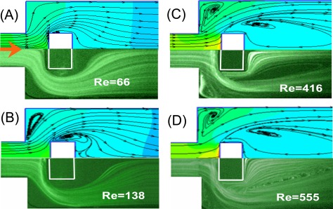
The flow fields developed within the microfluidic rectifier were investigated both numerically and experimentally for flow rates ranging from 0.09 ml/min to 4.00 ml/min; corresponding to Reynolds numbers in the range of Re = 12.8–555. Figures 4a, 4b, 4c, 4d show the numerical (upper) and experimental (lower) results obtained for the flow fields developed within the rectifier given forward flows with Reynolds numbers of Re = 66, 138, 416, and 555, respectively. As shown in Fig. 4a, given a Reynolds number of Re = 66, no flow vortices are formed within the expansion microchannel. However, two small vortices are induced beside the block structure. At a Reynolds number of Re = 138, the two vortices increase in size, and two new vortices are induced in the shoulders of the sudden expansion channel (Fig. 4b). As the Reynolds number is further increased, the size of all four vortices also increases (Figs. 4c, 4d). Given the maximum Reynolds number of Re = 555, the vortices adjacent to the embedded block and in the shoulders of the sudden expansion channel have a size of approximately 7 × 104 μm2 and 2 × 104 μm2, respectively. Consequently, for forward flows, the sudden expansion channel in the proposed rectifier acts simply as a diffuser since the effective width of the flow channel is always greater than the width of the input channel.
Figure 4.
Numerical (upper) and experimental (lower) visualization results for flow fields developed under different flow rates (Re) in forward direction.
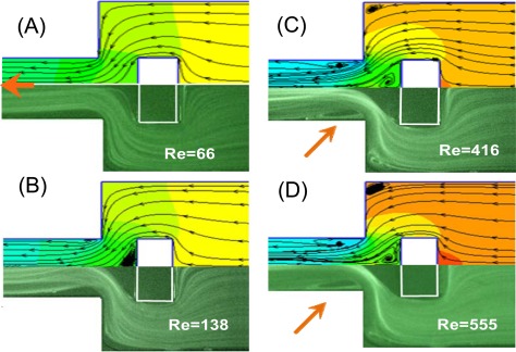
Figures 5a, 5b, 5c, 5d present the numerical and experimental results for the flow fields developed within the rectifier given reverse flows with Reynolds numbers of Re = 66, 138, 416, and 555, respectively. For a Reynolds number of Re = 66, the flow within the rectifier has a laminar characteristic (Fig. 5a). When the Reynolds number is increased to Re = 138, two small vortices are induced in front of the block structure (i.e., between the block structure and the exit of the microchannel) (Fig. 5b). As the Reynolds number is further increased to Re = 416 and Re = 555, respectively, vortices are formed in the shoulders of the sudden expansion channel and after the block in the expansion microchannel region (Figs. 5c, 5d). The vortices within the expansion microchannel reduce the effective hydraulic diameter of the channel. As a result, the flow resistance is increased and the flow rectification effect improved accordingly.
Figure 5.
Numerical (upper) and experimental (lower) visualization results for flow fields developed under different flow rates (Re) in reverse direction.
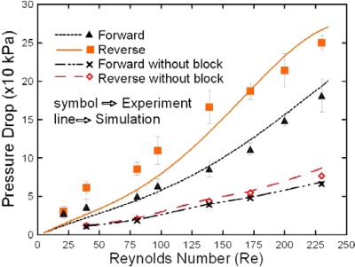
Figure 6 presents the numerical and experimental results for the variation of the pressure drop in the sudden expansion microchannel with the Reynold number for both forward and reverse flows. It is seen that for both flow directions, the pressure drop varies linearly with the Reynolds number when no block structure is embedded in the sudden expansion channel. However, a non-linear relationship is observed between the pressure drop and the Reynolds number when the block structure is introduced. It is seen that for both flow directions, the pressure drop within the sudden expansion microchannel increases when the block structure is introduced. Moreover, it is observed that for a given Reynolds number, the pressure drop for flow in the reverse direction is greater than that for flow in the forward direction. In other words, the flow rectification effect induced by the proposed device is confirmed.
Figure 6.
Numerical and experimental results for variation of pressure drop with Reynolds number. (Note that results are presented for forward flows and reverse flows both with and without the embedded block in the expansion channel.)
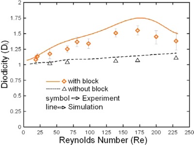
Figure 7 presents the numerical and experimental results for the variation of the diodicity with the Reynolds number with and without the embedded block structure, respectively. The results show that the rectification performance is improved by a factor of approximately 1.44 when the block structure is introduced into the sudden expansion channel. From inspection, the optimal diodicity is obtained at a Reynolds number of approximately Re = 172 and has a value of around 1.54 (experimental results) or 1.76 (numerical results). Table TABLE I. compares the rectification performance of the proposed device with that of three other valveless rectifiers presented in the literature. The performance of the microfluidic rectifier developed in this study is up to 30% higher than the rectifier adopted the cascade diffusers and nozzles.31 It is seen that the diodicity of the present device is around 12%–31% higher than that of the existing devices.
Figure 7.
Numerical and experimental results for diodicity of flow rectifier given different flow rates (Re). (Note that results are presented for the diodicity both with and without the embedded block in the expansion channel.)
TABLE I.
Experimental and numerical results for rectification performance (diodicity) of different valveless rectifiers.
CONCLUSION
This study has presented a microfluidic rectifier comprising a sudden expansion channel containing an embedded block structure. For forward flows, the sudden expansion channel acts as a simple diffuser at all values of the Reynolds number in the range of Re = 66–555. However, for reverse flows with a Reynolds number greater than Re = 138, flow vortices are formed within the sudden expansion microchannel. The vortices reduce the hydraulic diameter of the channel and, therefore, increase the flow resistance. Consequently, a flow rectification effect is achieved without the need for any moving parts. The experimental results have shown that the rectifier achieves a maximum diodicity of Di = 1.54 and therefore outperforms typical valveless rectifiers presented in the literature (e.g., Di = 1.15–1.35).
ACKNOWLEDGMENTS
The financial support provided to this study by the National Science Council of Taiwan under grant.
References
- Tsai C. H., Hou H. H., and Fu L. M., Microfluid. Nanofluid. 5, 827–836 (2008). 10.1007/s10404-008-0284-6 [DOI] [Google Scholar]
- Hong T. F., Ju W. J., Wu M. C., Tai C. H., Tsai C. H., and Fu L. M., Microfluid. Nanofluid. 9, 1125 (2010). 10.1007/s10404-010-0633-0 [DOI] [Google Scholar]
- Dimov I. K., Riaz A., Ducr J., and Lee L. P., Lab Chip 10, 1468 (2010). 10.1039/b925132d [DOI] [PubMed] [Google Scholar]
- Rosenauer M. and Vellekoop M. J., Biomicrofluidics 4, 043005 (2010). 10.1063/1.3502672 [DOI] [PMC free article] [PubMed] [Google Scholar]
- Cho S. H., Godin J. M., Chen C. H., Qiao W., Lee H., and Lo Y. H., Biomicrofluidics 4, 043001 (2010). 10.1063/1.3511706 [DOI] [PMC free article] [PubMed] [Google Scholar]
- Movahed S. and Li D., Microfluid. Nanofluid. 10, 703 (2011). 10.1007/s10404-010-0716-y [DOI] [Google Scholar]
- Jang Y. C., Jha S., Chand R., Islam K., and Kim Y. S., Electrophoresis 32, 913 (2011). 10.1002/elps.201000697 [DOI] [PubMed] [Google Scholar]
- Lin C. H., Wang Y. N., and Fu L. M., Biomicrofluidics 6, 012818 (2012). 10.1063/1.3654950 [DOI] [PMC free article] [PubMed] [Google Scholar]
- Hou H., Tsai C., Fu L., and Yang R., Electrophoresis 30, 2507 (2009). 10.1002/elps.200900012 [DOI] [PubMed] [Google Scholar]
- Wu C. Y., Liao W. H., and Tung Y. C., Lab Chip 11, 1740 (2011). 10.1039/c0lc00620c [DOI] [PubMed] [Google Scholar]
- Wu H. W., Hsu R. C., Lin C. C., Hwang S. M., and Lee G. B., Biomicrofluidics 4, 024112 (2010). 10.1063/1.3454767 [DOI] [PMC free article] [PubMed] [Google Scholar]
- Lim C. Y., Lam Y. C., and Yang C., Biomicrofluidics 4, 014101 (2010). 10.1063/1.3279790 [DOI] [PMC free article] [PubMed] [Google Scholar]
- Hou H. H., Wang Y. N., Chang C. L., Fu L. M., and Yang R. J., Microfluid. Nanofluid. 11, 479 (2011). 10.1007/s10404-011-0813-6 [DOI] [Google Scholar]
- Wen C. Y., Liang G. B., Chen H., and Fu L. M., Electrophoresis 32, 3268 (2011). 10.1002/elps.201100254 [DOI] [PubMed] [Google Scholar]
- Paul D., Saias L., Pedinotti J., Chabert M., Magnifico S., Pallandre A., Lambert B. D., Houdayer C., Brugg B., Peyrin J., and Viovy J., Biomicrofluidics 5, 024102 (2011). 10.1063/1.3569946 [DOI] [PMC free article] [PubMed] [Google Scholar]
- Ju W. J., Fu L. M., Yang R. J., and Lee C. L., Lab Chip 12, 622 (2012). 10.1039/c1lc20954j [DOI] [PubMed] [Google Scholar]
- Davies M. J., Johnston I. D., Tan C. K. L., and Tracey M. C., Biomicrofluidics 4, 044112 (2010). 10.1063/1.3528327 [DOI] [PMC free article] [PubMed] [Google Scholar]
- Yang S. Y., Cheng F. Y., Yeh C. S., and Lee G. B., Microfluid. Nanofluid. 8, 303 (2010). 10.1007/s10404-009-0461-2 [DOI] [Google Scholar]
- Peng X. Y., Lab Chip 11, 132 (2011). 10.1039/c0lc00037j [DOI] [PubMed] [Google Scholar]
- Tekin H. C., Sivagnanam V., Ciftlik A. T., Sayah A., Vandevyver C., and Gijs M. A. M., Microfluid. Nanofluid. 10, 749 (2011). 10.1007/s10404-010-0706-0 [DOI] [Google Scholar]
- Melvin E. M., Moore B. R., Gilchrist K. H., Grego S., and Velev O. D., Biomicrofluidics 5, 034113 (2011). 10.1063/1.3620419 [DOI] [PMC free article] [PubMed] [Google Scholar]
- Liou D., Hsieh Y., Kuo L., Yang C., and Chen P., Microfluid. Nanofluid. 10, 465 (2011). 10.1007/s10404-010-0681-5 [DOI] [Google Scholar]
- Ezkerra A., Fernández L. J., Mayora K., and Ruano-López J. M., Lab Chip 11, 3320 (2011). 10.1039/c1lc20324j [DOI] [PubMed] [Google Scholar]
- Abate A. R. and Weitz D. A., Biomicrofluidics 5, 014107 (2011). 10.1063/1.3567093 [DOI] [PMC free article] [PubMed] [Google Scholar]
- Hickerson A. I. and Gharib M., J. Fluid Mech. 555, 141 (2006). 10.1017/S0022112006009220 [DOI] [Google Scholar]
- Wen C. Y., Cheng C. H., Jian C. N., Nguyen T. A., Hsu C. Y., and Su Y. R., Mat. Sci. Forum 505–507, 127 (2006). 10.4028/www.scientific.net/MSF.505-507.127 [DOI] [Google Scholar]
- Oh K. W. and Ahn C. H., J. Micromech. Microeng. 16, R13 (2006). 10.1088/0960-1317/16/5/R01 [DOI] [Google Scholar]
- Loverich J., Kanno I., and Kotera H., Microfluid. Nanofluid. 3, 427 (2007). 10.1007/s10404-006-0127-2 [DOI] [Google Scholar]
- Tsai C. H., Chen H. T., Wang Y. N., Lin C. H., and Fu L. M., Microfluid. Nanofluid. 3, 13 (2007). 10.1007/s10404-006-0099-2 [DOI] [Google Scholar]
- Huang Y., Uppalapati M., Hancock W. O., and Jackson T. N., Biomed. Microdevices 9, 175 (2007). 10.1007/s10544-006-9019-1 [DOI] [PubMed] [Google Scholar]
- Nguyen N. T., Lam Y. C., Ho S. S., and Low C. L.N., Biomicrofluidics 2, 034101 (2008). 10.1063/1.2959099 [DOI] [PMC free article] [PubMed] [Google Scholar]
- Fadl A., Zhang Z., Geller S., Tölke J., Krafczyk M., and Meyer D., Microsyst. Technol. 15, 379 (2009). 10.1007/s00542-009-0901-7 [DOI] [Google Scholar]
- Liu J., Yap Y. F., and Nguyen N. T., Phys. Rev. E 80, 046319 (2009). 10.1103/PhysRevE.80.046319 [DOI] [PubMed] [Google Scholar]
- Singh K. P. and Kumar M., Biomicrofluidics 4, 034112 (2010). 10.1063/1.3492403 [DOI] [PMC free article] [PubMed] [Google Scholar]
- Sugita S., Murase T., Sakamoto N., Ohashi T., and Sato M., Lab Chip 10, 755 (2010). 10.1039/b920164e [DOI] [PubMed] [Google Scholar]
- Sousa P. C., Pinho F. T., Oliveira M. S. N., and Alves M. A., J. Non-Newtonian Fluid Mech. 165, 652 (2010). 10.1016/j.jnnfm.2010.03.005 [DOI] [Google Scholar]
- Yang K., Chen I., Wang C., and Shyu J., Microsyst. Technol. 16, 1691 (2010). 10.1007/s00542-010-1069-x [DOI] [Google Scholar]
- Tsai C. H., Yeh C. P., Lin C. H., Yang R. J., and Fu L. M., Microfluid. Nanofluid. 12, 213 (2012). 10.1007/s10404-011-0864-8 [DOI] [Google Scholar]
- Namdeo S., Khaderi S. N., den Toonder J. M. J., and Onck P. R., Biomicrofluidics 5, 034108 (2011). 10.1063/1.3608240 [DOI] [PMC free article] [PubMed] [Google Scholar]
- Kokot G., Vilfan M., Osterman N., Vilfan A., Kavčič B., Poberaj I., and Babič D., Biomicrofluidics 5, 034103 (2011). 10.1063/1.3608139 [DOI] [PMC free article] [PubMed] [Google Scholar]
- Hur S. C., Mach A. J., and Carlo D. D., Biomicrofluidics 5, 022206 (2011). 10.1063/1.3576780 [DOI] [PMC free article] [PubMed] [Google Scholar]
- Khaderi S. N., den Toonder J. M. J., and Onck P. R., Biomicrofluidics 6, 014106 (2012). 10.1063/1.3676068 [DOI] [PMC free article] [PubMed] [Google Scholar]
- Truong T. Q. and Nguyen N. T., Technical Proceedings of the 2003 Nanotechnology Conference and Trade Show (NIST, 2003), Vol. 1, pp. 171–181.
- Olsson A., Enoksson P., Stemme G., and Stemme E. E., J. Microelectromech. Syst. 6, 161 (1997). 10.1109/84.585794 [DOI] [Google Scholar]
- Yang K. S., Chen I. Y., and Wang C. C., Chem. Eng. Tech. 29, 703 (2006). 10.1002/ceat.200500275 [DOI] [Google Scholar]
- Wang C. T., Len T. S., and Sun J. M., J. Mech. 23, 9 (2007). 10.1017/S1727719100001027 [DOI] [Google Scholar]
- Groisman A. and Quake S. R., Phys. Rev. Lett. 92, 095401 (2004). 10.1103/PhysRevLett.92.094501 [DOI] [PubMed] [Google Scholar]
- Fu L. M. and Lin C. H., Biomed. Microdevices 9, 277 (2007). 10.1007/s10544-006-9036-0 [DOI] [PubMed] [Google Scholar]
- Lin C. H., Lee C. Y., Tsai C. H., and Fu L. M., Microfluid. Nanofluid. 7, 499 (2009). 10.1007/s10404-009-0403-z [DOI] [Google Scholar]
- Lee H. C., Hou H. H., Yang R. J., Lin C. H., and Fu L. M., Microfluid. Nanofluid. 11, 469 (2011). 10.1007/s10404-011-0812-7 [DOI] [Google Scholar]
- Hou H. H., Tsai C. H., Fu L. M., and Yang R. J., Electrophoresis 30, 2507 (2009). 10.1002/elps.200900012 [DOI] [PubMed] [Google Scholar]
- Lee C. Y., Wen C. Y., Hou H. H., Yang R. J., Tsai C. H., and Fu L. M., Microfluid. Nanofluid. 6, 363 (2009). 10.1007/s10404-008-0381-6 [DOI] [Google Scholar]


