Abstract
Four 12-rung linear birdcage-type coils were built to experimentally examine the effects of the end-ring/shield configuration on radiofrequency magnetic field (B1) homogeneity and SNR at 125 MHz. The coil configurations include (a) a cylindrical shield (conventional), (b) a shield with annular extensions to closely shield the end-rings (surrounding shield), (c) a shield with annular extensions connected to the rungs (solid connection), and (d) a shield with radially oriented conductors connected to the rungs (radial connection). These coils were also modeled closely with finite difference time domain (FDTD) methods to corroborate experimental findings. Images of a human head were acquired, and the signal-to-noise ratio (SNR) was measured on the central axial, sagittal, and coronal slices. B1 field homogeneity in the unloaded coils was assessed on images of an oil phantom. Among the four configurations, the solid connection configuration has a lower SNR than the conventional configuration and the surrounding shield configuration but a higher SNR than the radial connection. Although there is no significant difference between the overall SNR of the conventional configuration and the surrounding shield configuration, the surrounding shield configuration has the potential to be tuned to higher frequencies than the conventional configuration. The conventional birdcage coil results in the most homogeneous B1 field in the oil phantom. Numerical results are also compared with the experimental results.
Keywords: RF coil, end-ring, B1 homogeneity, SNR, FDTD
INTRODUCTION
Radiofrequency (RF) magnetic field (B1) homogeneity and SNR have always been important aspects of RF coil design in MRI. The RF field distribution depends on the details of the coil configuration. One aspect of this is current return path—namely, whether it is through end-rings (1, 2) or through the shield (3, 4 ). In previous calculations (5 ), four different end-ring/shield configurations were modeled to examine the effects of different current return paths on B1 homogeneity and SNR at 64 and 125 MHz. Configurations included (a) a cylindrical shield (conventional), (b) a shield with annular extensions to closely shield the end-rings (surrounding shield), (c) a shield with annular extensions connected to the rungs (solid connection), and (d) a shield with radially oriented conductors connected to the rungs (radial connection). It was found that the conventional configuration results in the highest homogeneity on an axial plane in the empty coil, whereas the surrounding shield configuration results in the highest homogeneity and the highest SNR on an axial plane in the coil loaded with a head at both frequencies, and the largest difference of the SNR between different configurations is less than 11%. In the calculations, a current distribution varying sinusoidally with the azimuthal angle, as ideally achieved in a quadrature coil, was assumed, and no matching circuit was modeled. In reality, both the matching circuit, which is needed in most cases to maximize the power transmission, and asymmetric loading of the coil by human subjects can disturb the current distribution in the coil and affect the performance of the coil.
In this work, four head-size birdcage-type coils for use at 125 MHz modeled in the calculations were constructed to examine the effects of the end-ring/shield configuration on B1 homogeneity and SNR experimentally. Images were acquired in an oil phantom and in a human head for all four configurations. B1 homogeneity in the central axial slice of the oil phantom and the SNR in the central axial, sagittal, and coronal planes was calculated and compared for different configurations. RF power absorption was also estimated.
Efforts were made to compare the experimental results to the previous numerical results (5 ), but modification of the previous calculations was required because of the difference in coil dimensions, structure, and drive method between the calculations and the experiments. The dimensions of the coils were initially planned to match those in the previous calculations, but because of limited available materials, they (26.0 cm coil diameter, 35.6 cm shield diameter, 20.3 cm length) were slightly different from previous calculations (27.0 cm coil diameter, 34.0 cm shield diameter, 22.0 cm length). The number of the rungs in each coil in the calculations was 16 while in the experiments it was decreased to 12 because the capacitors required to tune the low-pass 16-rung conventional coil to 125 MHz were too small (<1 pF). In the calculations, the coils were driven in quadrature with ideal voltage sources and no capacitors were modeled, whereas in experiments the coils were driven linearly, which was sufficient for our purpose. So in this study, the coils were remodeled with dimensions, structure, and drive method as close to those in experiments as possible, and the results of homogeneity and SNR were compared with the experiments.
METHODS
Mechanical Structure
Each coil was built on two coaxial acrylic cylinders with the smaller one (inner diameter of 26.0 cm) as the foundation of the coil and the larger one (outer diameter of 35.6 cm) as the foundation of the shield. Both cylinders have a wall thickness of 0.3 cm and a length of 20.3 cm. A delrin plate with inner diameter of 26.4 cm, outer diameter of 35.2 cm, and thickness of 0.8 cm was placed in the middle between the two cylinders to keep the cylinders in a coaxial position. Two delrin end plates with inner diameters of 26.0 cm, outer diameters of 35.6 cm, and thickness of 0.8 cm were attached to both ends of the cylinders and held together with the plate in the middle by six supporting delrin rods. The middle plate was also used to support the adjustable tuning and matching capacitors (Fig. 1).
Figure 1.
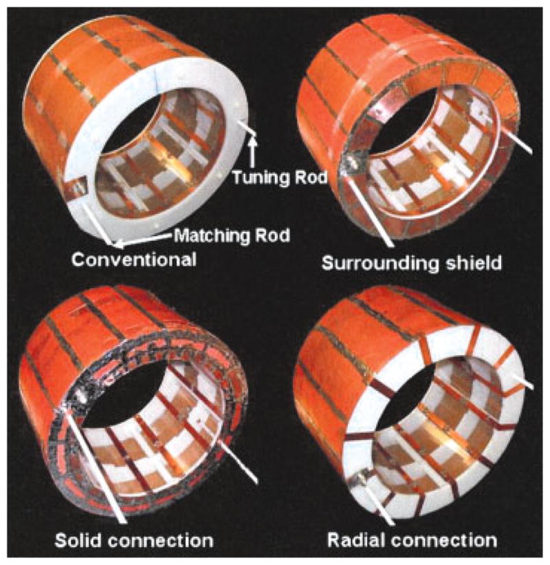
Four 12-rung low-pass linear birdcage-type coils with four different end-ring/shield configurations. [Color figure can be viewed in the online issue, which is available at www.interscience.wiley.com.]
Electrical Circuits
The coils were built as 12-rung linear low-pass birdcage type with different end-ring/shield configurations (see Fig. 1). All the configurations were built based on the conventional configuration. Initially, a conventional coil with 16 rungs, which was the number of the rungs in the previous calculations, was built, but the capacitor values needed to efficiently tune the coil to 125 MHz were too small (<1 pF). To build the conventional birdcage coil, 12 1.3-cm-wide and 20.3-cm-long strips of copper tape were oriented longitudinally and spaced evenly around the circumference on the inner surface of the smaller cylinder. Another 1.3-cm wide and 81.8-cm-long strip of copper tape was oriented in the circumferential direction and laid down on the top of and connected to the 12 rungs at each end of the cylinder to form the end-rings of the birdcage coil. The shield was a 20.3-cm-long cylinder made by putting strips of wide copper tape on the outside surface of the larger cylinder and soldering them together. The width of the rungs is similar to that of the manufactory birdcage coil that came with our Bruker system. The surrounding shield configuration had the same rungs and end-rings as the conventional configuration but the shield was extended inwardly to cover the outside surface of the two end plates. The inward part of the shield was 0.8 cm away from the end-rings in the axial direction. The solid configuration had the same structure as the surrounding shield configuration except that it had no separate end-rings at the end, and rungs were directly connected to the shield. The radial connection configuration had the same structure as the conventional configuration except that it had no separate end-rings and rungs were directly connected to the shield by extending across the end plates in the radial direction. The length of the rungs in the conventional configuration and in the surrounding shield configuration was 2.9 cm shorter than that in the solid connection and radial connection due to the width of the end-rings and the thickness of the end plates. This difference in rung length is the result of an effort to keep the length of the shield the same for the surrounding shield configuration and the solid connection configuration. Solid shields instead of slotted shields, which are used to reduce eddy currents caused by fast gradient switching, were used here because the slotted shields were difficult to model in FDTD with limited spatial resolution. No image sequences that require fast gradient switching, such as echo planar imaging (EPI), were used in this study to avoid inducing significant eddy currents in the shields.
Tuning and Matching
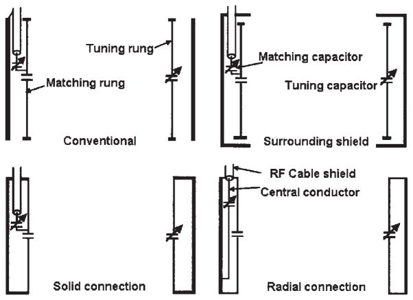
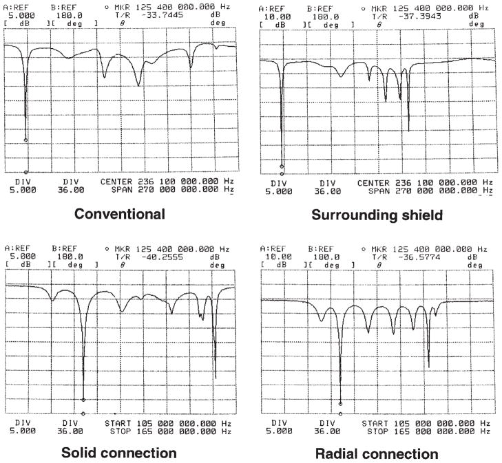
Three narrow gaps, with a capacitor placed across each of them, were cut into each rung except for the rungs attached with the adjustable matching capacitor (the matching rung) and with the adjustable tuning capacitor (the tuning rung, or the rung opposite the matching rung), where the number of gaps was either one or three. This was an effort to choose the capacitor values to minimize the perturbation of the matching circuit. A schematic diagram of matching circuits in the four coils is shown in Fig. 2. For all configurations except the radial connection one, the central conductor of the RF cable was connected in series to an adjustable capacitor, which was then connected to one side of the fixed capacitor in the middle of the matching rung. The RF cable shield was connected to the coil shield (6 ). For the radial connection, an inductive drive loop (see Fig. 2) was used to decrease the imbalance introduced by the driving mechanism (3, 7 ). The transmission return loss curve is plotted in Fig. 3 for each configuration when it was loaded with a subject’s head. Resonant mode 1, which was identified as the mode that produces a homogeneous RF field in the coil (measured with a shielded pickup coil of 2.9 cm diameter), was tuned to 125.44 MHz, and the impedance of the coil loaded with the head was matched to 50 ohms at that frequency. The capacitor values in the matching rung, tuning rung, and the other rungs are shown in Table 1. Note that the capacitance in the matching rung referred to the value of the fixed disc capacitor in the middle of the rung. An adjustable matching capacitor was also attached to the matching rung at one point as shown in Fig. 2 except in the radial connection configuration, where the variable matching capacitor was embedded in the separate driving loop.
Figure 2.
A schematic diagram of the matching circuit for the four configurations. In each case, the RF cable shield is soldered to the top of coil shield.
Figure 3.
Transmission return loss curves for the four coils. The displays for the conventional configuration and the surrounding shield configuration span over 270 MHz, whereas those for the solid connection configuration and the radial connection configuration span over 60 MHz.
Table 1.
Capacitor Values of the Four Coils
| Experiment
|
Calculation
|
|||
|---|---|---|---|---|
| Matching Rung | Tuning Rung | Other Rungs | Each Rung | |
| Conventional | 2.2 pF | Variable | 1.42 pF | 2.4 pF |
| Surrounding | 2.7 pF | Variable | 2.73 pF | 3.8 pF |
| Solid connection | 6.8 pF | Variable | 7.33 pF | 6.85 pF |
| Radial connection | 5.63 pF | Variable | 6.21 pF | 5.34 pF |
A variable tuning capacitor, ranging from 1 pF to 12 pF, was placed in the middle of the tuning rung, and a fixed-value capacitor was placed in the middle of the matching rung. Another variable capacitor, ranging from 1 pF to 12 pF, was also attached to the matching rung (see Fig. 2) to match the coil to 50 ohms. The matching circuit was not modeled in the calculations.
Q values for unloaded coils (Qunloaded) and the coils loaded with the subject’s head (Qloaded) were determined by doubling the measured ratio of center frequency to −3 dB bandwidth on the return loss curves using an HP network analyzer 4195A, because loading a matched network analyzer halves the Q values of the circuit (8, 9).
Imaging Parameters
Fast spin-echo images (10) of five axial, sagittal, and coronal slices in the head of a normal Asian male subject (age 30, 170 cm, 79.4 kg) were acquired on a whole-body MEDSPEC S300 2.94 T research imaging spectrometer (Bruker Instruments, Inc., Karlsruhe, Germany) with TR = 4680 ms, TE = 80.4 ms, matrix size = 256 × 256, NEX = 2, FOV = 25 cm, slice thickness = 5 mm, slice interval = 5.5 mm, and RARE factor = 8. SNR was measured with the signal averaged from all brain tissues and divided by the standard deviation of background noise in the image plane and all the SNRs were normalized to the SNR in the conventional configuration. The input RF power was also normalized to that in the conventional coil.
Gradient echo images of a cylindrical vegetable oil phantom (diameter = 24.7 cm, height = 22.9 cm) were also acquired on the same system to estimate the homogeneity as in the unloaded coils (11, 12) with TR = 5000 ms, TE = 6 ms, matrix size = 256 × 256, NEX = 1, FOV = 30 cm, slice thickness = 5 mm, and flip angle = 45°. The coils were retuned and rematched for the oil phantom. Here the homogeneity is defined as the percentage of the area on the central axial plane within 70% of the coil radius that has image signal intensity (SI) deviation within 10% of the average image intensity (|SI(r) − SIaverage|/SIaverage < 0.1).
Calculations
Four 12-rung linear low-pass birdcage-type coils (36 cm shield diameter, 26 cm coil diameter, and 20.5 cm height) were modeled either empty or loaded with a head model as described previously (5 ) but with geometries more accurately matching those of the coils just described at 125 MHz. Twelve capacitors, whose values are shown in Table 1 with the experimental values, were modeled in each coil to tune it to the resonant frequency (13). Each coil was driven with a single current source in parallel with one of the 12 capacitors. The spatial resolution is 5 mm × 5 mm × 5 mm in three dimensions, and the coil or the head was kept at least 24 cm away from the outer boundary (Liao boundary). Steady-state electromagnetic fields were calculated with a commercial software package (XFDTD, Remcom, State College, PA), and the methods to calculate the component of the B1 field rotates with ( ) or against ( ) the spin precession, RF power absorption, and SNR were described previously (5 ). Homogeneity on the central axial slice in the empty coils and SNR on central axial, sagittal, and coronal slices in the head were calculated. The homogeneity was defined in the empty coil as the percentage of the area within 70% of the coil radius that has deviation within 10% of the average .
RESULTS
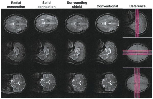
The images of the axial, sagittal, and coronal slices passing through the center of the coil for the four coils loaded with the subject’s head are shown in Fig. 4, with the reference images showing the slice positions in the head. The central axial slice for the oil phantom is shown in Fig. 5 with the dashed line indicating the outer boundary of the area within which the homogeneity was calculated. Table 1 contains the capacitor values used in the experiments and calculations. The homogeneity in the oil phantom, the Q values, and the input RF power for the head imaging are shown in Table 2, with the calculation results of homogeneity in the empty coil and the RF power absorbed in the head model. The SNR on the central axial, sagittal, and coronal planes in the head both in experiments and calculations is listed in Table 3 for the four coils.
Figure 4.
Image slices of a subject’s head in the four coils. Only the central slices are shown here. [Color figure can be viewed in the online issue, which is available at www.interscience.wiley.com.]
Figure 5.
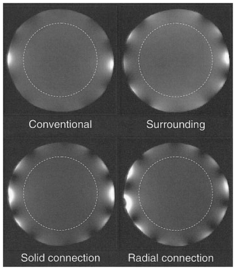
The central axial image slice of the oil phantom for the four coils. The circle of the dashed line, which has a diameter about 70% of that of the coil, indicates the outer boundary of the area within which the homogeneity was calculated.
Table 2.
Q Values, Transmitting RF Power P, and Homogeneity for the Four Coils in the Experiments and the Calculations
| Q
|
P (dB)
|
Homogeneitya in Unloaded Coils
|
||||
|---|---|---|---|---|---|---|
| Unloaded | Loaded | Exp. | Calc. | Exp. | Calc. | |
| Conventional | 128 | 20 | 0 | 0 | 78.7 | 95.9 |
| Surrounding | 162 | 40 | 0 | −0.2 | 40.1 | 87.9 |
| Solid connection | 222 | 40 | 0.5 | 0.5 | 54.5 | 89.7 |
| Radial connection | 248 | 48 | 1.3 | 1.5 | 37.6 | 86.7 |
The RF power was measured for a 3.2-ms 90-degree Gauss pulse during head imaging and was normalized such that the power used by the conventional coil was equal to 0 dB. Exp. = experiments; Calc. = calculations.
The homogeneity in the experiments was defined as the percentage of the area on the central axial plane in the oil phantom within 70% of the coil radius that had image signal intensity deviation within 10% of the average image signal intensity. The homogeneity in calculations was defined as the percentage of the area on the central axial plane in the empty coil within 70% of the coil radius that had deviation within 10% of the average .
Table 3.
Signal-to-Noise Ratio on the Central Slices in the Head
| Axial
|
Sagittal
|
Coronal
|
||||
|---|---|---|---|---|---|---|
| Exp. | Calc. | Exp. | Calc. | Exp. | Calc. | |
| Conventional | 1 | 1 | 1 | 1 | 1 | 1 |
| Surrounding | 1.04 | 1.11 | 1.02 | 1.02 | .96 | 1.02 |
| Solid connection | .96 | .98 | .85 | .99 | .90 | 1.11 |
| Radial connection | .76 | .88 | .74 | .88 | .76 | 1.03 |
Exp. = experiments; Calc. = calculations.
DISCUSSION
Matching and Tuning
In both experiments and calculations, the capacitor values in the conventional configuration and the surrounding shield configuration were smaller than those in the solid connection and the radial connection, indicating larger total equivalent inductance in the conventional and the surrounding shield configuration than that in the other two configurations (14 ). The difference of capacitor values between the experimental results and the calculations could be a result of the matching circuit (not modeled in calculations), or of the limited ability of the FDTD method to accurately model conductor cross-sections, and thus coil inductance. The calculated values are close enough to be used as initial values in the coils’ fine tuning process. Compared with the conventional configuration, the surrounding shield configuration has less total inductance, so it could be tuned to a higher frequency. It was also found that during the tuning and matching process, the surrounding shield configuration and the solid connection configuration are less sensitive to the change of outside environment (e.g., position of the RF cable in the magnet, experimenter’s body position, and so on) than the conventional and the radial connection configuration due to the shielding effects of the solid end plates (see Fig. 1).
The wider distribution of modes in the frequency spectrum (see Fig. 3) of the conventional configuration and of the surrounding shield configuration makes the coils more immune to coupling between modes introduced by perturbation of the matching circuit than the solid connection and the radial connection configuration (15 ). It is found that even a 3% change of the capacitor in the matching rung in the solid connection (from 6.8 pF to 7 pF) dramatically changes the homogeneity of the image (increased image intensity next to the matching rung and decreased image intensity next to the tuning rung; images not shown here).
B1 Homogeneity
Considering that the oil phantom occupied about 90% of the coil cross-section area, the images in Fig. 5 show good homogeneity in the oil phantom in all four coils. The higher image intensity at the left and right edges of the image is caused by the high current density in the matching and tuning rungs. The lower image intensity area (dark holes) at the edge is the result of the cancellation of the fields from adjacent rungs. The pattern of the dark holes in the conventional coil is less strong than that in the other three coils. In the solid connection and radial connection configuration, the pattern becomes more obvious and extended toward the center of the image. The quantitative homogeneity measured from the area within the dashed line (diameter of 18 cm, 70% of the coil diameter) in Fig. 5 is the highest in the conventional coil. This result is also verified in the calculations (see Table 2). The experimentally measured homogeneity in all coils is less than that in the calculations, but the trend within the coils are the same with the conventional coil ranking the highest and the radial connection the lowest. One reason the homogeneity in the experiments is less than that in the calculations is the image intensity, which is used to evaluate the homogeneity in experiments and is proportional to times the sine of the flip angle, varies spatially more than does, which is used in calculations to evaluate the homogeneity. Because it is difficult to quantitatively evaluate the B1 homogeneity in the head, only image slices are shown in this work (see Fig. 4). The central axial images show good homogeneity in all four coils except that in the images taken with the solid connection configuration the left side is slightly brighter than the right side. This inhomogeneity is due to perturbation introduced by the matching circuit and may be eliminated by adjusting the capacitance in each rung carefully (as often done in a TEM coil). Some signal loss is observed on the top of the sagittal slice and coronal slice in the conventional configuration and the surrounding shield configuration, but the brain tissue is still clear.
SNR
In the experiments, the surrounding shield configuration results in the highest SNR in the central axial plane in the head. The SNR in the central axial plane in the surrounding shield configuration is about 4.0% higher than that in the conventional configuration, about 8.3% higher than that in the solid connection configuration, and about 37% higher than that in the radial connection configuration. The surrounding shield configuration also results in the highest SNR in the central sagittal plane. The SNR in the central sagittal plane in the surrounding shield configuration is about 2.0% higher than that in the conventional coil, about 20% higher than that in the solid connection configuration, and about 38% higher than that in the radial connection. The conventional configuration results in SNR in the central coronal plane is about 4.2% higher than the surrounding shield, about 11% higher than the solid connection configuration, and about 32% higher than the radial connection configuration. The conventional configuration and the surrounding shield configuration result in SNRs in all three planes significantly higher than the solid connection configuration, which results in SNRs in all three planes significantly higher than the radial connection. There is no significant difference of the overall SNR between the conventional configuration and surrounding shield configuration. The main reason the solid connection configuration results in lower SNR than the conventional and the surrounding shield configuration might be that the solid connection configuration is more sensitive to the perturbation of the field introduced by the matching circuit. As seen in the transmission return loss curves in Fig. 3, the mode 1 in the conventional configuration and the surrounding shield configuration is separated from the adjacent modes by at least 30 MHz, whereas in the solid connection and the radial connection by less than 10 MHz. The asymmetry introduced by the match circuit in the solid connection and the radial connection is more likely to increase coupling between modes and degrades both the homogeneity and SNR. Compared with that in the experiments, the smaller difference of SNR between the solid/radial connection and conventional/surrounding shield configuration in the calculations (solid connection and radial connection even have SNR higher than the conventional configuration on the coronal plane), where no matching circuits were modeled, also supports this explanation.
The input RF power necessary for the coils is consistent with the SNR performance of the coils with less power required for coils with greater SNR in general. The surrounding shield configuration uses the same power as the conventional configuration. The solid connection configuration uses 0.5 dB more power, and the radial connection configuration uses 1.3 dB more power than the conventional configuration. The calculated power absorption in the head model matches the power required in the experiments closely. Q values for loaded and unloaded cases are within reasonable range, but there is no relation between the SNR and the ratio of Qunloaded to Qloaded. This observation is consistent with the theory that Q plays a less direct role in in vivo MRI when sample noise is much larger than coil noise (9).
In this work we have attempted to keep all things constant between the coils except for the current return path or shielding thereof. Certainly, each of the configurations studied could benefit from optimization of several other parameters, such as length and diameter of coil and shield, number of rungs, capacitor placement (high-pass vs. low-pass), and capacitor type (distributed and/or individually-adjustable vs. lumped element).
CONCLUSIONS
Conventional and surrounding shield configurations have better homogeneity and SNR than the solid and radial connection configurations in this study. Arrangements where individual rung impedances can be adjusted to compensate for perturbation induced by matching circuit may improve the situation for coils with return paths through the shield. Though there is no significant difference between the overall SNR of the conventional configuration and the surrounding shield configuration, the surrounding shield configuration has the potential to be tuned to higher frequencies than the conventional configuration. Numerical calculations can provide useful information to aid experimental coil design.
Acknowledgments
This research was funded in part by the National Institute of Biomedical Imaging and Bioengineering (NIH R01 EB 000454).
References
- 1.Hayes CE, Edelstein WA, Schenck JF, Mueller OM, Eash M. An efficient, highly homogeneous radiofrequency coil for whole-body NMR imaging at 1.5T. J Magn Reson. 1985;63:622–628. [Google Scholar]
- 2.Collins CM, Li S, Smith MB. SAR and B1 field distributions in a heterogeneous human head model within a birdcage coil. Magn Reson Med. 1998;40:847–856. doi: 10.1002/mrm.1910400610. [DOI] [PubMed] [Google Scholar]
- 3.Bridges JF. Cavity resonator with improved magnetic field uniformity for high frequency operation and reduced dielectric heating in NMR imaging devices. 4 751 464 US patent. 1988
- 4.Barfuss H, Fischer H, Hentschel D, Ladebeck R, Oppelt A, Wittig R, et al. In vivo magnetic resonance imaging and spectroscopy of humans with a 4T whole-body magnet. NMR Biomed. 1990;3:31–45. doi: 10.1002/nbm.1940030106. [DOI] [PubMed] [Google Scholar]
- 5.Liu W, Collins CM, Delp PJ, Smith MB. Effects of end-ring/shield configuration on homogeneity and signal-to-noise ratio in a birdcage-type coil loaded with a human head. Magn Reson Med. 2004;51:217–221. doi: 10.1002/mrm.10683. [DOI] [PubMed] [Google Scholar]
- 6.Roemer PB, Edelstein WA, Hayes CE, Eash MG. Method for providing multiple coaxial cable connections to a radio-frequency antenna without baluns. 4 887 039 US patent. 1989
- 7.Hoult DI, Tomanek B. Use of mutually inductive coupling in probe design. Concepts Magn Reson B (Magn Reson Eng) 2002;15:262–285. [Google Scholar]
- 8.Chen C-N, Hoult D. Biomedical magnetic resonance technology. New York: Adam Hilger; 1989. [Google Scholar]
- 9.Hayes CE, Edelstein WA, Schenck JF. Radio frequency resonators. In: Partain CL, Price RR, Patton JA, et al., editors. Magnetic resonance imaging. Vol. 1. Philadelphia: W.B. Saunders; 1988. pp. 1193–1195. [Google Scholar]
- 10.Henning J, Nauerth A, Friedburg H. RARE imaging: a fast imaging method for clinical MR. Magn Reson Med. 1986;3:823–833. doi: 10.1002/mrm.1910030602. [DOI] [PubMed] [Google Scholar]
- 11.Zhang X, Ugurbil K, Chen W. A microstrip transmission line volume coil for human head MR imaging at 4 T. J Magn Reson. 2003;161:242–251. doi: 10.1016/s1090-7807(03)00004-1. [DOI] [PubMed] [Google Scholar]
- 12.Vaughan JT, Garwood M, Collins CM, Liu W, Dela-Barre L, Adriany G, et al. 7T vs. 4T: RF power, homogeneity, and signal-to-noise comparison in head images. Magn Reson Med. 2001;46:24–30. doi: 10.1002/mrm.1156. [DOI] [PubMed] [Google Scholar]
- 13.McKinnon G, Wang Z. Direct capacitor determination in FDTD modeling of RF coils. Proceedings of the 11th annual meeting ISMRM; Toronto, Ontario, Canada. 2003. p. 2381. [Google Scholar]
- 14.Tropp J. Mutual inductance in the bird-cage resonator. J Magn Reson. 1997;126:9–17. doi: 10.1006/jmre.1997.1149. [DOI] [PubMed] [Google Scholar]
- 15.Tropp J. A model for image shading in multimode resonators. Proceedings of the 9th annual meeting ISMRM; Glasgow, Scotland. 2001. p. 1129. [Google Scholar]


