Abstract
The ability to concentrate biological cells, such as circulating tumor cells, circulating fetal cells, and stem cells, is an important issue in medical diagnostics and characterization. The present study develops a handheld device capable of effectively preconcentrating cancerous cells. Circular microelectrodes were designed to generate a stepping electric field by switching the electric field to an adjacent electrode pair by relays. Cancerous cells with a positive dielectrophoretic response are guided toward the center of the circular microelectrodes due to the region of high electric field between the adjacent electrodes being gradually decreased in the direction of the stepping electric field. Numerical simulations of the electric fields were performed to demonstrate the concept of the proposed design. The preconcentration of HeLa cells, which are a human cervical carcinoma cell line, was achieved in 160 s with an efficiency of around 76%, with an applied peak-to-peak voltage of 16 V at a frequency of 1 MHz.
INTRODUCTION
The manipulation of biological cells is essential to many biomedical applications, such as the isolation and detection of rare cancer cells, the concentration of cells from dilute suspensions, the separation of cells according to specific properties, and the trapping or positioning of individual cells for characterization. Among these applications, concentrating rare cells, such as circulating tumor cells (CTC), circulating fetal cells, and stem cells, is an important technique in biological and clinical studies.1, 2 A highly sensitive and specific identification of CTC could prove helpful in the early diagnosis of invasive cancers.3 The methods of CTC detection can be generally divided into cytometric- and nucleic-acid-based techniques, both of which require an enrichment and detection procedure.1, 4 Numerous methods for concentrating biological cells have been proposed,1, 5 such as immuno-affinity, filtration (ISET, isolation by size of epithelial tumor cells),6 fluorescence-activated cell sorting (FACS), magnetic-activated cell sorting (MACS),7 cell surface markers, and dielectrophoresis. Fu et al.8 reported a microfabricated fluorescence-activated cell sorting (μFACS) device for Escherichia coli HB101 cells. The cells are manipulated electrokinetically at a T-shaped fluidic junction on their chip, which is mounted on an inverted optical microscope, and fluorescence is readout with a photomultiplier tube. Koo et al.9 reported the application of biotinylated heat-shock protein 60 as a capture molecule for viable Listeriamonocytogenes in a microfluidic channel. A dielectrophoretic force generated by interdigitated electrodes is employed to increase the capture rate. Dielectrophoresis (DEP) is achieved under a non-uniform electric field generated by various electrode patterns, insulating structures, or their combination. Early studies on dielectrophoretic response adopted large electrodes, such as needles, pins, wires, and sheets.10, 11 Microfabrication technology was later employed to create microelectrode patterns, which allowed sufficiently large DEP forces to be generated to manipulate particles with small applied voltages. The direction of the DEP force is controlled by the dielectric properties of the particles and medium, which are functions of frequency. This has been widely used for the manipulation of particles in diverse microdevices. Geometrical constrictions in insulating structures have been proposed to produce non-uniform electric fields by squeezing the electric field in a conductive medium, termed insulator-based DEP (iDEP).12 An approach for the DEP field-flow separation of cells utilizing a DEP chip filter, in which a non-uniform electric field is generated by the insertion of dielectric silica beads between two wire-meshed parallel plates, has been proposed.13 A microfluidic device composed of a series of microchannels constructed with insulating microstructures for the concentration of micro/nanoparticles using direct current (DC) dielectrophoresis in a continuous fluid flow was proposed by Chen and Du.14 All the incoming particles are trapped when a sufficiently high voltage (>400 V) is applied. Microelectrode patterns used for DEP have been previously reviewed.15, 16 Bacterial cells were trapped using electrophoresis generated by a set of interdigitated electrodes in a continuous flow.17 By closing the microvalves after trapping the bacterial cells in the sample, the volume is reduced, and therefore, the locally detectable concentration of genetic material is enhanced. Four trapezoidally arranged electroplated gold electrodes and substrate interconnections were designed for trapping a single cell by dielectrophoresis.18 Moon et al.19 have proposed a microfluidic device consisted of serially integrated multi-orifice flow fractionation (MOFF) and dielectrophoretic cell separators, which was capable of high-speed continuous separation, and separated human breast cancer cells from a blood cell sample. Cells were separated based first on their size in the MOFF channel and then on their dielectrophoretic properties in the DEP channel. Microfluidic devices with vertical interdigitated electrodes embedded in the channel sidewalls were designed for cellular separation by dual-frequency coupled dielectrophoretic forces.20 Dielectrophoresis generated by three-dimensional carbon electrodes was integrated with a compact disk (CD)-based centrifugal microfluidic platform to enhance filtering efficiency.21 The isolation of HeLa cells from normal peripheral blood cells has been achieved on a silicon chip containing a five-by-five array of microlocations due to the differences in their dielectric properties.22 Gascoyne et al.23 reported an approach for isolating malaria-parasitised cells by dielectrophoretic manipulation in spatially inhomogeneous, travelling electrical fields. Applying four-phase signals to a spiral array of four parallel microelectrodes caused normal erythrocytes to be trapped at the electrode edges, whereas parasitised cells were levitated and carried towards the centre of the spiral by the travelling field. Dielectrophoresis produces contactless and gentle forces on cells, making it particularly suitable for cell manipulation in a microchip.16 In our previous study,24 interdigitated curvy electrodes were designed to generate the stepping electric fields by switching the electric field to an adjacent electrode pair via relays, which were controlled by an 8-bit microcontroller. Our previous results demonstrated that positive dielectrophoretic cells could be conveyed along the direction of the stepping electric field powered by a function/arbitrary waveform generator. In the present study, a handheld device that comprises a voltage-frequency converter and an operational amplifier substituting for the function generator to energize the stepping electric fields is developed. Moreover, a dielectrophoretic cellular microchip with circular microelectrodes for the rapid collection of cancerous cells is proposed to enhance the performance of preconcentration. An experiment is conducted to demonstrate the capability of the proposed device to concentrate cells. The quantitative efficiency of cellular concentration for various time intervals of relay switching is also investigated in this work.
THEORY AND DESIGN
The DEP force (FDEP) acting on a spherical particle of radius R suspended in a fluid with permittivity is given as
| (1) |
where Re(fCM) is the real part of the Clausius-Mossotti factor and Erms is the root-mean-square of the external electric field in an alternating current (AC) field. The Clausius-Mossotti factor (fCM) is a parameter of the effective polarizability of a particle. It varies with the complex dielectric properties of the particle and the surrounding medium, which are functions of the frequency of the applied field (f). The Clausius-Mossotti factor for a spherical particle is represented as
| (2) |
where and are the complex permittivities of the particle and the medium, respectively. The complex permittivity is related to the conductivity σ and angular frequency ω(=2πf) as
| (3) |
where j equals . Therefore, the DEP force depends mainly on the difference between the dielectric properties of the particles and those of the suspending medium solution. The DEP force can be either positive, pulling particles toward the region with a high electric-field gradient, or negative, repelling particles away from the region with a high electric-field gradient. Dielectric properties of viable mammalian cells can be formulated using the protoplast model, which is based on a spherical particle consisting of a cytoplasm and a lossless capacitive membrane.25, 26 The effective permittivity can be derived by neglecting the conductance of the membrane in the protoplast model; thus, the Clausius-Mossotti factor for viable cells can be rewritten as
| (4) |
where and are the time constants, and and are the electrical conductivity and permittivity of the cytoplasm, respectively. The parameters and R represent the effective capacitance of the membrane and the radius of the cell, respectively. Moreover, the constants and can be defined as and , respectively, where and are the electrical conductivity and permittivity, respectively, of the suspension medium. Based on the protoplast model, viable HeLa cells in a sucrose medium (ɛr = 78; σ = 1.76 × 10⁻³ S/m) exhibit a strongly positive dielectrophoretic response; i.e., the Clausius-Mossotti factor is 1.0 at a high frequency of 1 MHz.26
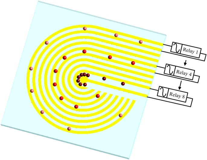
The operational concept of the cellular concentration is illustrated in Fig. 1. When an electric field is applied to the two adjacent microelectrodes, a high-electric-field region is generated between the electrode pair. The applied electric field is subsequently switched to the adjacent electrode pair by relays (from the outermost to the center pair of microelectrodes) to generate a stepping electric field. Positive dielectrophoretic cells are guided along the direction of the stepping electric field due to the movement of the high-electric-field region to the center of the circular electrode. The high-electric-field region between adjacent electrodes gradually shrinks towards the center. As a result, the cells are concentrated onto the central microelectrode.
Figure 1.
Operation concept of the cellular preconcentrator by dielectrophoresis in a stepping electric field.
A numerical simulation of the electric field was performed using the commercial software package CFD-ACE+ (ESI Group, France). The finite element method and three-dimensional structured grids were employed to solve the governing equation for the electric potential φ in the medium, which can be expressed as
| (5) |
where and are the conductivity and permittivity of the medium, respectively. The current continuity equation is solved by assuming a sinusoidal steady state. After converting the current continuity equation into the frequency domain, where the electric potential becomes a complex quantity, the following equation is obtained:
| (6) |
Since the electric potential of the above equation is complex, that is, , the following two equations must be solved:
| (7) |
| (8) |
The electric field is assumed to be unaffected by the presence of particles in the simulation for simplicity.
EXPERIMENTAL SECTION
Chip fabrication
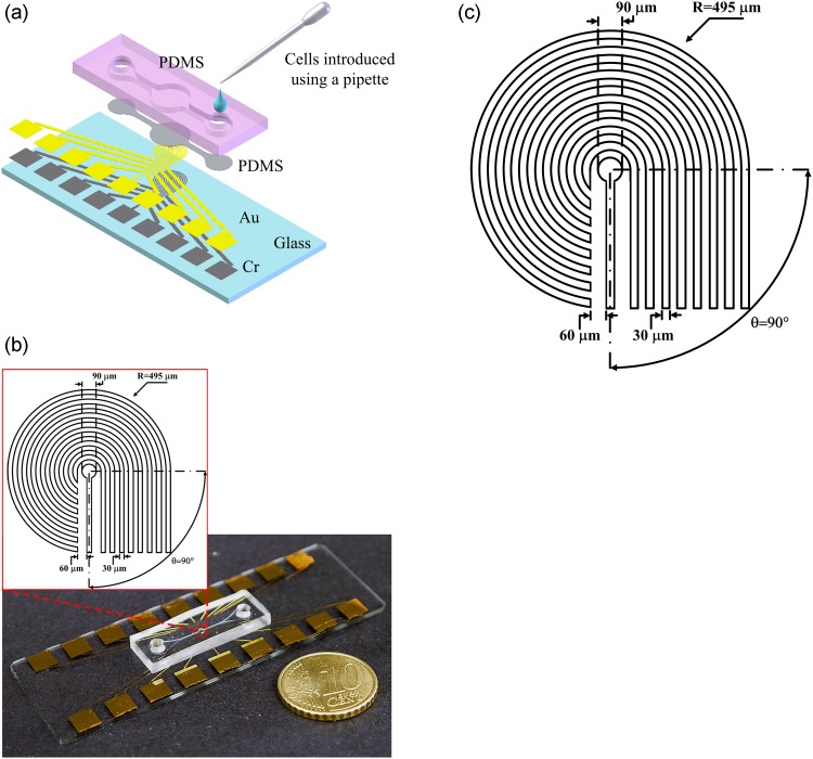
A biocompatible material, polydimethylsiloxane (PDMS), was adopted for the microchamber in the cellular preconcentrator. A schematic of the microchip with circular microelectrodes is illustrated in Fig. 2a. The cells were introduced into the microchamber using a pipette. The microchip was fabricated in-house using standard soft lithography techniques. The electrodes were made by depositing chrome (20 nm) and gold (100 nm) sequentially onto slides, which were cleaned in piranha solution (a mixture of sulfuric acid and hydrogen peroxide). The PDMS prepolymer mixture (Sylgard-184 Silicone Elastomer Kit, Dow Corning, Midland, MI, USA) was diluted with hexane, with a PDMS to hexane weight ratio of 1:5. The 3-μm-thick hexane-diluted PDMS prepolymer was spin-coated onto the electrodes to prevent electrolysis and cell adherence to the electrodes. The mold master was fabricated by spinning 100-μm-thick SU-8 (SU-8 50, MicroChem Corp., Newton, MA, USA) onto a silicon wafer to define the microchamber. Undiluted PDMS prepolymer mixture was poured into the mold master and cured to fabricate the microchamber. After the PDMS had been peeled off, the inlet and outlet ports were made by a puncher, and the replica with the microchamber was bonded to the glass substrate after treatment with oxygen plasma in an O2 plasma cleaner (Model PDC-32G, Harrick Plasma Corp., Ithaca, NY, USA). The fabricated chip for cellular preconcentration is shown in Fig. 2b. The radius of the microchamber is 600 μm. The width of electrodes and the gap between them were both 30 μm, and the radius of curvature for the circular microelectrodes was 495 μm, as shown in Fig. 2b.
Figure 2.
(a) Schematic diagram of the cellular preconcentrator using dielectrophoresis; (b) image of fabricated chip and dimensions of the circular microelectrodes; (c) complete handheld device with electric module providing the stepping electric field.
Apparatus
Two 12-V DC sources were used as the power supply for the handheld device. An IC MAX 038 (MAXIM, USA) voltage-frequency converter and an AD817 amplifier (Analog Devices, USA) were employed in the design of an AC signal source that creates the electric fields required for the dielectrophoretic enrichment in the microchamber. An 8-bit microcontroller with 4 kB of flash memory (AT89C51, Atmel) was adopted to control the eight relays that generate the stepping electric fields. The circuit module was made on a printed circuit board (PCB). The microchip was mounted on the handheld module, which generated the stepping electric field for cellular preconcentration, as shown in Fig. 2c. Most existing dielectrophoretic approaches including our previous work24 employed a function/arbitrary waveform generator to provide the required electric field for dielectrophoresis. A handheld electric module with a voltage-frequency converter and an operational amplifier was developed in this study, making it low-cost and automated. The cells were observed and recorded using an inverted fluorescence microscope (Model CKX41, Olympus, Tokyo, Japan), a mounted CCD camera (DP71, Olympus, Tokyo, Japan), and a computer with Olympus DP controller image software. An image of the microelectrodes and microchamber taken by the optical microscope is shown in the inset of Fig. 2c.
Cell sample preparation
A human cervical carcinoma cell line (HeLa cells) was cultured for an experimental demonstration of cellular preconcentration using the proposed handheld microdevice. The cells were serially passaged as monolayer cultures in DMEM medium (Gibco, Grand Island, NY, USA), with 3.7 g of NaHCO3 per liter of medium added, supplemented with 10% fetal bovine serum (FBS, Gibco, Grand Island, NY, USA) and 1% penicillin/streptomycin (Gibco, Grand Island, NY, USA). The cell culture dish (Falcon, Franklin Lakes, NJ, USA) was incubated in a humidified atmosphere containing 5% carbon dioxide at 37 °C; the medium was replaced every 1 to 2 days. Cells grown to sub-confluence were washed with phosphate-buffered saline (PBS, Biochrome, pH 7.4) and harvested by a 5-min treatment with 0.25% Trypsin and 0.02% EDTA (Sigma, USA). The cells were stained using a standard fluorescence assay with calcein AM (Molecular Probes, Eugene, OR, USA) prior to the experiment to determine the viability of cells. Calcein AM is a green fluorescent dye, which is able to penetrate the cell membrane into the cytosol and transform into a fluorescent form when it is hydrolyzed by esterases located inside cells. The cell samples were then suspended in an 8.62 wt. % sucrose solution with a measured conductivity of 1.76 × 10⁻³ S/m. For the dielectrophoresis of cells, the sucrose solution was employed to increase the osmolarity to normal physiological levels.
RESULTS AND DISCUSSION
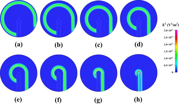
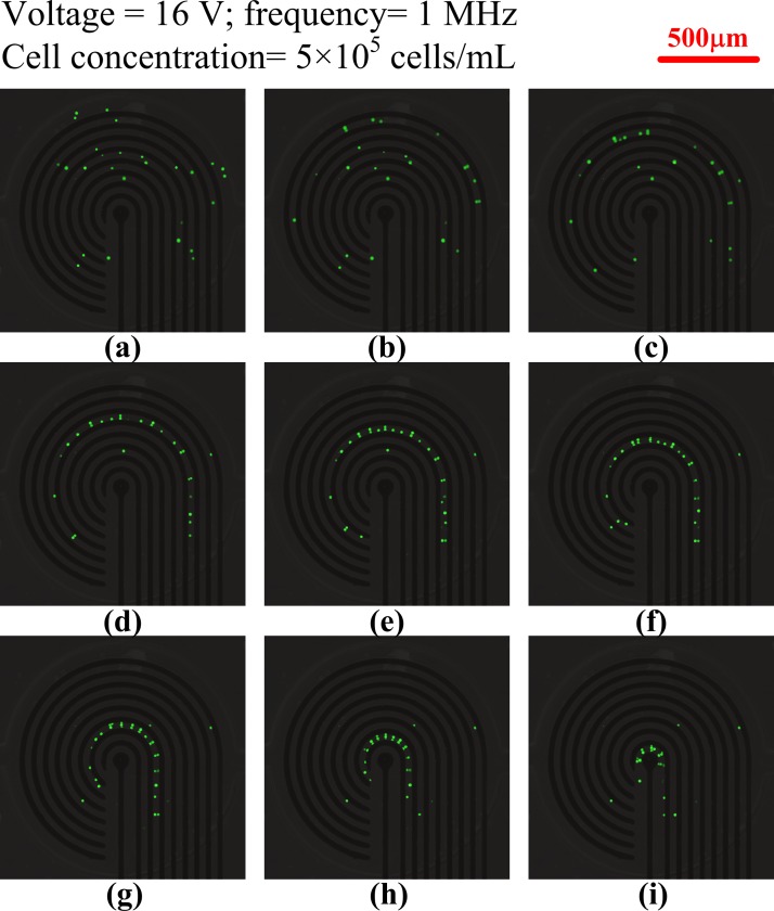
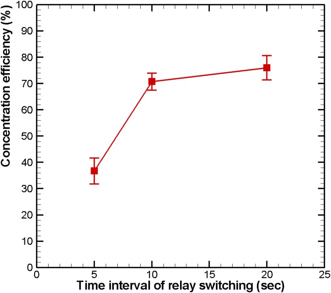
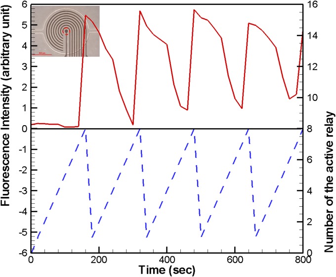
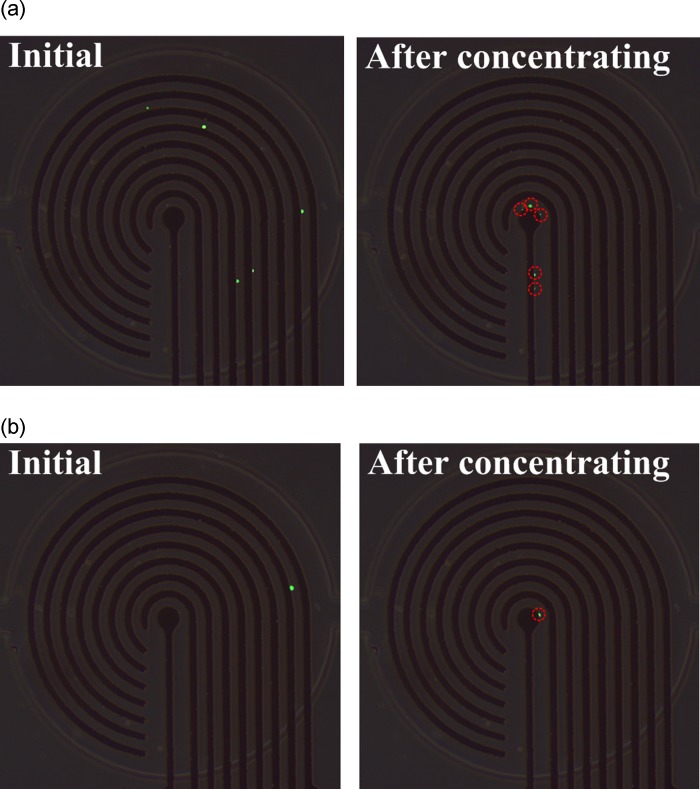
The simulated square of the electric field (E2) with 16 V applied from the outermost microelectrode pair to the central microelectrode pair by switching relays is shown in Fig. 3. The numerical results indicate that the high-electric-field region moved to where the electric field was applied, and decreased according to the pattern of the microelectrodes. Therefore, HeLa cells, which have a positive dielectrophoretic response at a frequency of 1 MHz, were guided along the direction of the stepping electric field, which is toward the center of the microchamber, and concentrated at the central pair of electrodes. The circular electrode (90 μm in diameter) at the center, shown in Fig. 2b, has a higher electric field than that along the 30-μm-wide straight electrode connected to the circular electrode mentioned above. The experimental results for cellular concentration are shown in Fig. 4. The HeLa cells, with a density of 5 × 10⁵ cells/ml, were introduced into the microchamber using a pipette. The electrodes were powered by a peak-to-peak voltage of 16 V at a frequency of 1 MHz. The electric field at the outermost pair of electrodes was turned on to attract cells. The electric field was held for about 20 s and then switched to the adjacent pair of electrodes. HeLa cells became concentrated between the powered electrodes and were guided to the center of the microchamber along the direction of the stepping electric fields. The time required to concentrate the cells from the outermost to the central pair of microelectrodes was about 160 s. The experimental results indicate that the HeLa cells were concentrated at the center pair of microelectrodes. High strength of electric fields, long exposure of time, or both could result in rupture of the cell membrane and cell lysis.27, 28 The field strength required for lysis of mammalian cells was in the order of magnitude of 106 V/m.29 The electric field strength applied herein (approximate 5 × 10⁵ V/m, 1 MHz) was lower than the threshold strength of cell lysis to maintain the viability of cells. The fluorescent images of cells stained by calcein AM in Fig. 4 also demonstrated that all the cells retained their viability after dielectrophoretic concentrating in the present microchip. Furthermore, the effect of the time interval of relay switching on the concentration efficiency was investigated. The efficiencies of cellular concentration for various time intervals of relay switching are shown in Fig. 5. In order to evaluate the concentrating efficiency quantitatively, the cellular density of 5 × 10⁵ cells/ml was employed; thereby, approximate 50 to 60 cells were in the microchamber. The experimental data are based on manual counts of cells for at least three separate runs using an inverted fluorescence microscope. Each experimental data point represents the average value of the three runs, and the error bar depicts the standard error from the mean. The concentration efficiency increased with the time interval of relay switching. However, the improvement in concentration efficiency decreased with increasing time interval. The experimental results reveal that the HeLa cells were concentrated at the center pair of microelectrodes with an efficiency of around 76%, when the time interval of relay switching was set to 20 s. The entire region of the microchamber with circular electrodes was affected by the dielectrophoretic force, comparing to our previous microchip with curvy electrodes.24 The efficiency of cellular preconcentration herein was higher than that in our previous design with an efficiency of 63%. The fluorescence intensity at the center of the microelectrodes was quantified using NIH IMAGEJ software. The fluorescence intensity at the center of the microelectrodes is shown in Fig. 6; the electric field was applied from the outermost to the center pair of microelectrodes. The region used for fluorescence intensity measurements is shown in the inset. The relays are numbered one to eight from the outer side to the center. The intensity of fluorescence increases abruptly if the relay is switched from the outermost to the center pair of electrodes (from relays 1 to 8). When the relay is switched from relays 1 to 8 again, the fluorescence intensity decreases in the beginning because the cells are diffused since the electric field at the center is removed. The intensity of fluorescence increases sharply when relay 8 is turned on again. This procedure was repeated five times; the maximum intensity, while relay 8 is turned on, decreased after the fourth time (about 640 s) due to the decay of the fluorescent dye. Samples containing less than 1000 target cells per ml are being considered to contain rare cells.5 Therefore, the experiments on samples with lower cellular density were performed in this study. The experimental results for cellular concentration with the cellular densities of 5 × 10⁴ and 103 cells/ml were revealed in Fig. 7. When the cellular density of HeLa cells was 5 × 10⁴ cells/ml, five cells, which were randomly distributed in the microchamber at the beginning, were guided to the center electrode after dielectrophoretic concentrating. Even only one single cell in the microchamber, when the HeLa cells with a cellular density of 103 cells/ml were introduced, the cell was concentrated to the center microelectrode. These results indicate that the HeLa cells can be collected at the center electrode, making the proposed device suitable for the detection and characterization of cells. The results presented in this work exhibited the capability of concentrating cancerous cells with a comparable efficiency compared to other approaches.19, 22, 23 However, this handheld device is very simple and economical.
Figure 3.
Simulation results of the square of the electric field (E2) with the electric field applied from the outermost microelectrode pair the center pair of microelectrodes by switching relays. The voltage applied to the electrode pair is 16 V.
Figure 4.
Experimental results of the concentration of HeLa cells. The peak-to-peak voltage and frequency applied were 16 V and 1 MHz, respectively. The time interval of relay switching was 20 s. The duration from (a) to (i) was approximately 160 s.
Figure 5.
Concentration efficiency of HeLa cells for various time intervals of relay switching. The peak-to-peak voltage and frequency applied were 16 V and 1 MHz, respectively. The squares represent the average value of at least three separate runs using three different microchips. The error bar depicts the standard error of the mean.
Figure 6.
Fluorescence intensity at the center of the microelectrode with the electric field applied from the outermost electrodes to the center pair of microelectrodes by switching relays, repeated five times. The relays are numbered one to eight from the outer side to the center. The inset shows the region used for fluorescence intensity measurements.
Figure 7.
Experimental results of the concentration of HeLa cells with cellular densities of (a) 5 × 10⁴ and (b) 103 cells/ml. The peak-to-peak voltage and frequency applied were 16 V and 1 MHz, respectively. The time interval of relay switching was 20 s.
CONCLUSION
A handheld device that comprises stepping electric fields and a dielectrophoretic microchip with a circular microelectrode for concentrating cancerous cells was proposed and demonstrated. The positive dielectrophoretic cells were guided by the movement of the high-electric-field region. The cells were concentrated at the center pair of microelectrodes due to the fact that the area of high electric field between adjacent electrodes gradually decreased from the outermost to the center pair of microelectrodes. The experimental results indicate that the HeLa cells were concentrated at the center pair of microelectrodes with an efficiency of around 76% when the time interval of relay switching was set to 20 s. The proposed microdevice for cellular concentration in this study is capable of enhancing the sensitivity of further CTC detections. The proposed handheld device can also be applied in point-of-care applications. However, detailed investigations on different cell lines and cellular density as well as the optimal design for large sample volume are required in future work.
ACKNOWLEDGMENTS
The authors acknowledge the National Science Council of the Republic of China for its financial support of this research under grants NSC 99-2923-E-194-001-MY3 and NSC 99-2221-E-194-014. The National Center for High-Performance Computing is also acknowledged for providing computer time and access to its facilities.
References
- Mostert B., Sleijfer S., Foekens J. A., and Gratama J. W., Cancer Treat. Rev. 35, 463 (2009). 10.1016/j.ctrv.2009.03.004 [DOI] [PubMed] [Google Scholar]
- Cheng X., Gupta A., Chen C., Tompkins R. G., Rodriguez W., and Toner M., Lab Chip 9, 1357 (2009). 10.1039/b818813k [DOI] [PMC free article] [PubMed] [Google Scholar]
- Paterlini-Brechot P. and Benali N. L., Cancer Lett. 253, 180 (2007). 10.1016/j.canlet.2006.12.014 [DOI] [PubMed] [Google Scholar]
- Grodzinski P., Yang J., Liu R. H., and Ward M. D., Biomed. Microdevices 5, 303 (2003). 10.1023/A:1027357713526 [DOI] [Google Scholar]
- Dharmasiri U., Witek M. A., Adams A. A., and Soper S. A., Ann. Rev. Anal. Chem. 3, 409 (2010). 10.1146/annurev.anchem.111808.073610 [DOI] [PubMed] [Google Scholar]
- Vona G., Sabile A., Louha M., Sitruk V., Romana S., Schütze K., Capron F., Franco D., Pazzagli M., Vekemans M., Lacour B., Bréchot C., and Paterlini-Bréchot P., Am. J. Pathol. 156, 57 (2000). 10.1016/S0002-9440(10)64706-2 [DOI] [PMC free article] [PubMed] [Google Scholar]
- Jacob K., Sollier C., and Jabado N., Expert Rev. Proteomics 4, 741 (2007). 10.1586/14789450.4.6.741 [DOI] [PubMed] [Google Scholar]
- Fu A. Y., Chou H. P., Spence C., Arnold F. H., and Quake S. R., Anal. Chem. 74, 2451 (2002). 10.1021/ac0255330 [DOI] [PubMed] [Google Scholar]
- Koo O. K., Liu Y., Shuaib S., Bhattacharya S., Ladisch M. R., Bashir R., and Bhunia A. K., Anal. Chem. 81, 3094 (2009). 10.1021/ac9000833 [DOI] [PubMed] [Google Scholar]
- Pohl H. A., Dielectrophoresis (Cambridge University Press, New York, 1978). [Google Scholar]
- Jones T. B. and Kraybill J. P., J. Appl. Phys. 60, 1247 (1986). 10.1063/1.337345 [DOI] [Google Scholar]
- Lapizco-Encinas B. H., Simmons B. A., Cummings E. B., and Fintschenko Y., Electrophoresis 25, 1695 (2004). 10.1002/elps.v25:10/11 [DOI] [PubMed] [Google Scholar]
- Iliescu C., Xu G. L., Ong P. L., and Leck K. J., J. Micromech. Microeng. 17, S128 (2007). 10.1088/0960-1317/17/7/S10 [DOI] [Google Scholar]
- Chen D. and Du H., Microfluid. Nanofluid. 9, 281 (2010). 10.1007/s10404-009-0545-z [DOI] [Google Scholar]
- Ramos A., Morgan H., Green G. N., and Castellanos A., J. Phys. D: Appl. Phys. 31, 2338 (1998). 10.1088/0022-3727/31/18/021 [DOI] [Google Scholar]
- Voldman J., Annu. Rev. Biomed. Eng. 8, 425 (2006). 10.1146/annurev.bioeng.8.061505.095739 [DOI] [PubMed] [Google Scholar]
- Lagally E. T., Lee S. H., and Soh H. T., Lab Chip 5, 1053 (2005). 10.1039/b505915a [DOI] [PubMed] [Google Scholar]
- Voldman J., Gray M. L., Toner M., and Schmidt M. A., Anal. Chem. 74, 3984 (2002). 10.1021/ac0256235 [DOI] [PubMed] [Google Scholar]
- Moon H. S., Kwon K., Kim S. I., Han H., Sohn J., Lee S., and Jung H. I., Lab Chip 11, 1118 (2011). 10.1039/c0lc00345j [DOI] [PubMed] [Google Scholar]
- Wang L., Lu J., Marchenko S. A., Monuki E. S., Flanagan L. A., and Lee A. P., Electrophoresis 30, 782 (2009). 10.1002/elps.200800637 [DOI] [PubMed] [Google Scholar]
- Martinez-Duarte R., R. A.GorkinIII, Abi-Samra K., and Madou M. J., Lab Chip 10, 1030 (2010). 10.1039/b925456k [DOI] [PubMed] [Google Scholar]
- Cheng J., Sheldon E. L., Wu L., Heller M. J., and O’Connell J. P., Anal. Chem. 70, 2321 (1998). 10.1021/ac971274g [DOI] [PubMed] [Google Scholar]
- Gascoyne P., Mahidol C., Ruchirawat M., Satayavivad J., Watcharasit P., and Becker F. F., Lab Chip 2, 70 (2002). 10.1039/b110990c [DOI] [PMC free article] [PubMed] [Google Scholar]
- Jen C. P., Huang C. T., and Chang H. H., Microelectron. Eng. 88, 1764 (2011). 10.1016/j.mee.2010.12.038 [DOI] [Google Scholar]
- Jones T. B., Electromechanics of Particles (Cambridge University Press, New York, 1995). [Google Scholar]
- Jen C. P. and Chen T. W., Biomed. Microdevices 11, 597 (2009). 10.1007/s10544-008-9269-1 [DOI] [PubMed] [Google Scholar]
- Lu K. Y., Wo A. M., Lo Y. J., Chen K. C., Lin C. M., and Yang C. R., Biosens. Bioelectron. 22, 568 (2006). 10.1016/j.bios.2006.08.009 [DOI] [PubMed] [Google Scholar]
- Brown R. B. and Audet J., J. R. Soc. Interface. 5, S131 (2008). 10.1098/rsif.2008.0009.focus [DOI] [PMC free article] [PubMed] [Google Scholar]
- Han F., Wang Y., Sims C. E., Bachman M., Chang R., Li G. P., and Allbrittion N. L., Anal. Chem. 75, 3688 (2003). 10.1021/ac0341970 [DOI] [PubMed] [Google Scholar]


