Abstract
Fast detection of waterborne pathogens is important for securing the hygiene of drinking water. Detection of pathogens in water at low concentrations and minute quantities demands rapid and efficient enrichment methods in order to improve the signal-to-noise ratio of bio-sensors. We propose and demonstrate a low cost and rapid method to fabricate a multi-layer polymeric micro-sieve using conventional lithography techniques. The micro-fabricated micro-sieves are made of several layers of SU-8 photoresist using multiple coating and exposure steps and a single developing process. The obtained micro-sieves have good mechanical properties, smooth surfaces, high porosity (≈40%), and narrow pore size distribution (coefficient of variation < 3.33%). Sample loading and back-flushing using the multi-layer micro-sieve resulted in more than 90% recovery of pathogens, which showed improved performance than current commercial filters.
INTRODUCTION
Fast detection of waterborne pathogens in potable water with high sensitivity is a scientific challenge and is important for securing the hygiene of drinking water. Detection of microorganisms in water at low concentrations and minute quantities demands rapid and efficient enrichment methods in order to improve the signal-to-noise ratio of subsequent determination methods.1, 2 Standard detection methods for viable bacteria are time-consuming and most often require a cultivation step for the microorganisms.3, 4 The bacterial samples are plated on culturing plates and incubated at various temperatures and times. Depending on the type of bacteria, this cultivation step can take up to several days. After the incubation period, the numbers of colony-forming units (cfu) are determined by visually counting the number of bacterial colonies.5, 6
Over the past decades, filtration based concentration techniques have been used extensively for capturing and recovering of waterborne pathogens.6 Available commercial microfilters normally suffer from major micro-structural defects which can compromise their efficiency for isolation of microorganism and enrichment step.7
Micro-fabricated filters, typically made using MEMS techniques, contain pores with the same size and shape, and can thoroughly overcome these micro-structural defects. The fabrication process allows enough flexibility to control the microfilter characteristics like pore size and density in order to have higher flow rate, lower clogging ratio, and better recovery rate.8, 9 In recent years, different methods have been proposed to create membranes with cylindrical pores like laser interference lithography and silicon micro machining technology,8 aperture array lithography,10 nanoimprinting using alumina template,11 excimer laser,12 phase separation micromolding,13 and more recently dissolving mold technique.14 However, some major impediments such as difficulty in demoulding, membrane failure (or folding) upon release from the master mold, low-yield, and costly processes make these methods unreliable for mass production purpose. Therefore, it is desirable to further improve the fabrication methods of micro-filters.
For this purpose, we employed conventional lithography and MEMS techniques, which are widely used in the semiconductor industry, for fabrication of a robust polymeric micro-filter. We utilized SU-8 (MicroChem Corp., Newton, MA) as a potential material for membrane fabrication because it is an epoxy-type photoresist with suitable chemical and mechanical properties that have been used widely for the development of complex features like multi-level microstructures.15, 16 Technically, fabrication of small micro-holes (i.e., 0.5–5 μm) inside a thick SU-8 film is impossible due to the tapering effect,17, 18 which normally happen during UV exposure (i.e., usually top layer is overexposed and tends to be wider than the bottom layer which is relatively underexposed, resulting in the variation of the lateral dimensions). To overcome this impediment, we employed multi-level lithography technique to fabricate polymeric membrane using multiple coating and exposure steps and a single developing process. With this process, we can have a great control of pore size in manufacturing robust micro/nano-sieves.
MATERIALS AND METHODS
Fabrication of perforated membrane
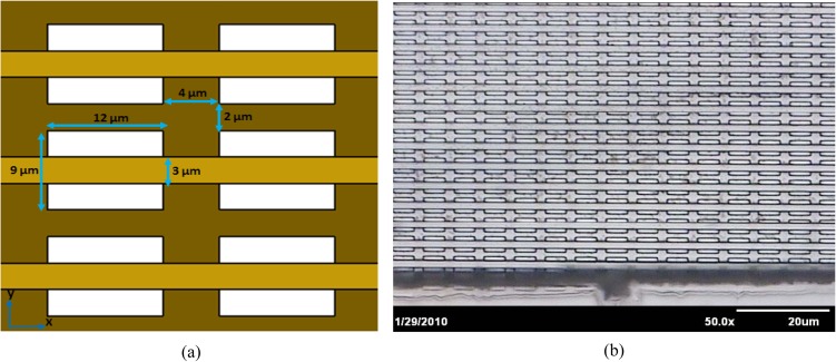
SU-8 2010 and SU-8 2015 (MicroChem Corp.) were used for the development of multi-layer polymeric micro-filter. The schematic representation of the entire fabrication process is illustrated in Figure 1. First, a standard 100 mm diameter, (1,0,0)-oriented silicon, was cleaned carefully in piranha solution (96% H2SO4 and 30% H2O2) for 20 min at 120 °C to remove any organic contaminations on the wafer surface. After rinsing with de-ionized (DI) water and drying with N2 gas, the substrate was submerged in the buffered oxide etchant (BOE) for 3 min to clean the natural oxide layer. The dehydration bake step was performed under vacuum in Suss machine (Delta 150 VPO) for 2 min. This step has a significant impact on adhesion of sacrificial layer to the substrate. To facilitate the release of membrane from the substrate, a thin layer of AZ 9260 (Microchemicals GmbH) was spin-coated on the silicon wafer and cured on a hot plate at 110 °C for 10 min (Fig. 1a). After curing the sacrificial layer (i.e., AZ 9260) and cooling down the wafer to the room temperature, a 10 μm thin layer of SU-8 photoresist (SU-8 2010, MicroChem Corp.) was spin-coated on the top of cured AZ 9260 film. In order to avoid bubbles, the photoresist was poured onto the substrate directly from a bottle with a large aperture. Soft baking process was performed on a carefully leveled hot plate at 65 °C for 1 min and 95 °C for 5 min, followed by 10 min relaxation at 25 °C (Fig. 1b). Baking steps are really crucial in order to reduce the internal stress in the final film.19 After soft baking the SU-8 on the hot plate, a chrome coated glass mask with rectangular features (12 × 9 μm) was used to transfer the patterns into the SU-8 photoresist. The pitch size (i.e., distance between mask features in x and y-directions) was 4 μm and 2 μm in x and y-directions, respectively (see Fig. 2a). UV-Lithography was processed by Karl Suss MA6 mask aligner (Karl Suss Inc.) in the vacuum contact mode between the silicon wafer and the mask with a 350 W mercury lamp with a high pass UV filter in order to cut off undesired short wavelength (i.e., exposed for 14 s corresponding to a dose of 120 mJ/cm2). Then SU-8 was kept again on the hot plate around 5 min for post-exposure at 95 °C and cooled down to the room temperature for relaxation purpose for 15 min. In this step, the cationic photo-polymerization of the epoxy is performed. Those parts which received UV light cross-linked to each other, which rendered permanent (i.e., dark brown areas in Fig. 1c) and the areas that are not exposed will be removed, as by solvent, during the development process.
Figure 1.
Fabrication process of multi-layer polymeric micro-sieve, (a) spin coating of sacrificial layer on the Si substrate, (b) spin coating of first layer of SU-8, (c) exposure through the first quartz mask (i.e., dark brown areas are exposed area), (d) spin coating of second layer of SU-8, (e) exposure through the second quartz mask (i.e., dark brown areas are exposed area), (f) spin coating of third layer of SU-8, (g) exposure through the foil mask (i.e., dark brown areas are exposed area), and (h) simultaneous development of all three layers and release of membrane from the Si substrate by dissolving the sacrificial layer.
Figure 2.
(a) Schematic and (b) optical image of a multi-layer polymeric micro-sieve with critical dimensions.
A micro-fabricated membrane must be robust enough to endure the pressure of filtration. A key parameter which has a direct effect on the membrane strength is the thickness of sieving layer. As discussed earlier, due to the non-uniform UV exposure dose in a thick SU-8 film, usually the top layer is overexposed and tends to be wider than the bottom layer which is relatively underexposed, resulting in pore closure.
To solve this problem, we proposed a novel solution to make large holes in the first layer and then reduce the pore size by laying parallel strips in the middle of the pores. For this purpose, a second layer of SU-8 2010 with 10 μm thickness was spin-coated on top of the first layer (Fig. 1d). After soft baking the second layer on the hot plate (i.e., at 65 °C for 1 min and 95 °C for 4 min, 10 min relaxation at 25 °C), another quartz/chrome mask with array of strips features (3 μm width) was used to transfer the pattern precisely in the middle of previous features (Fig. 1e). Alignment of the second mask with patterns on the first layer was carried out using precise microscopes of Karl Suss MA6 mask aligner, and exposure was performed for 12 s with UV dosage of 120 mJ/cm2. To avoid excessive stress, adhesion failure, and pattern dimensional change, exposure dose must be adjusted according to the substrate or under layer reflectivity.16 For this case, finding the optimum dose for the second layer was a serious challenge, because an extra or not sufficient dosage could lead to the pore occlusion and pattern failure. After exposing the second layer, wafer was kept again on the hotplate at 95 °C for the post exposure and cooled down to the room temperature for relaxation purpose for 10 min. Similar to the previous step, those areas that exposed are cross-linked to each other, which rendered permanent (i.e., dark brown areas in Fig. 1e) and the areas that are not exposed will be removed during development step by developer.
Figure 2 shows the schematic and optical image of a membrane, which was obtained with this technique. It can be seen that array of parallel strips (3 μm width) perfectly placed at the center of rectangular (12 × 9 μm) pores. The final pores are high aspect ratio slits with 12 × 3 μm dimensions that can be used for different applications such as Cryptosporidium parvum oocysts isolation, blood filtration, and protein purification.
Fabrication of support structure
In order to improve the strength of the micro-fabricated micro-sieves, we used a thick layer of SU-8 (SU-8 2015, MicroChem Corp.) to make a back side support with large openings. For this purpose, a third layer of SU-8 film with thickness of 20 μm was spin-coated on top of the second layer (Fig. 1f). After soft baking on the hotplate for around 40 min, third exposure through a plastic mask with square shape openings (600 × 600 μm) was carried out to form the support layer with 600 μm apertures in the backside of the double layer membrane (Fig. 1g). Following third exposure, the substrate was held on the hotplate for around 25 min for post-exposure and also good adhesion to the second layer. After cooling down to the room temperature with slow ramping, all the SU-8 levels were developed at room temperature in propylene-glycol-methyl-ether-acetate (PGMEA) simultaneously (Fig. 1h). This single developing step process provides important advantages over a process where each coated layer is developed prior to coating of subsequent layers. For example, simultaneous development of multiple SU-8 layers significantly reduces the processing time. Additionally, coating uniformity is increased compared to a process that coats over the topography of previously patterned layers. With this method, membranes with different thickness and pore size can be produced.
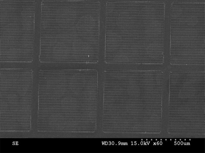
In order to release the membrane from the substrate, we put the wafer inside an acetone bath for around 5 min with ultrasonic agitation. Ultrasonic agitation is necessary for releasing the membrane from the substrate because, first, it expedites the releasing process and second, it prevents the adhesion of SU-8 film to the substrate when the sacrificial layer is dissolving in the solvent. The following SEM photo (Fig. 3) shows a micro-fabricated multi-layer micro-sieve with integrated back support mesh and close-up view shows how the array of stripes perfectly placed between the rectangular slits on the first layer.
Figure 3.
SEM image of a polymeric multi-layer micro-sieve with integrated back-support. Close-up view shows the perforated micro-sieve.
Figure 4 depicts the back-side view of a multi-layer micro-sieve. This picture reveals that obtained membrane has a smooth surface and high porosity, which make it ideal for microfiltration of biological samples like blood cells or isolation of microorganisms such as C. parvum oocysts. It should be noted that support’s openings must be large enough to do not contribute any significant effect to the total hydraulic resistance to flow across the membranes.10, 20
Figure 4.
Back-side view of a polymeric multi-layer micro-sieve with slit-shape openings (3 × 12 μm) and integrated support mesh.
RESULTS AND DISCUSSION
Membrane properties
By employing conventional lithography technique, we demonstrated a quick process for fabrication of micro-filters for biological purposes like concentration of bacteria and microorganism removal from drinking water. SU-8 was employed in this study because it is a widely used material for different microfabrication applications and can be deployed as a structural layer for different MEMS and bio-MEMS devices. Moreover, SU-8 is a biocompatible polymer with good thermal and chemical stabilities that has been used for many biomedical and biological applications.21
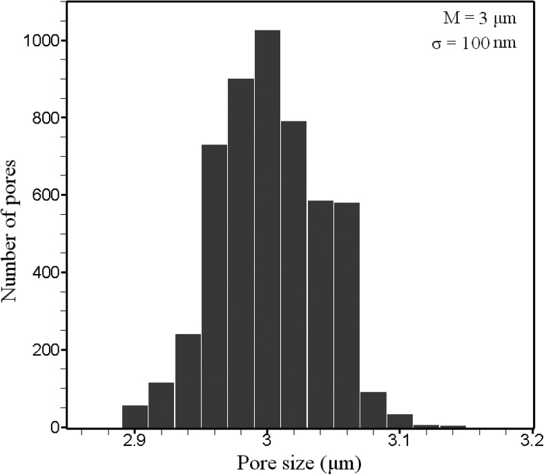
The measurement of the pore-size distribution of the SU-8 membranes was carried out using digitalized photographs from HITACHI S3500 scanning electron microscope machine, which is equipped with the “in-built dimension measurement” module and image analysis program SEMICAPS 2200 (Semicaps Pte Ltd.) from random regions of the samples. The mean pore width was 3 μm and standard deviation was 100 nm, respectively. Therefore, corresponding coefficient of variation (CV = σ/M) is 3.33%. This value may vary from one sample to another sample due to the misalignment or any changes in the fabrication parameters like exposure dose, development time, etc. By employing multi-layer technology, membranes with pore density of about 6 × 10⁷ pores/cm2 were fabricated. The pore density of polymeric micro-fabricated membrane is much higher than the commercial filter like polymeric track-etched membrane with CV and average pore density of around 20% and 107 pores/cm2, respectively.20, 22 The histogram of analyzed samples is depicted schematically in Figure 5.
Figure 5.
Pore size distribution of a polymeric multi-layer micro-sieve with 3 × 12 μm slit-shape perforations.
Filtration throughput
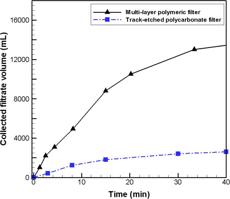
Figure 6 illustrates the filtrate collection volume data of the micro-fabricated multi-layer membrane and a track-etched polycarbonate membrane (Millipore, pore size of 3 μm, Cat. No. TSTP02500) under a constant pressure condition using tap-water. The operating pressure was 0.5 bar and the turbidity was around 0.4 nephelometric turbidity unit (NTU). The thickness of both membranes was 20 μm. A pressurized container was used to generate constant pressure filtration data. Permeate was collected in a container located on an electronic scale. The results indicate that the micro-fabricated polymeric filter has a higher throughput in comparison to the track-etched membrane for the same purpose (i.e., five times more). This can be attributed to the higher porosity and slit shape openings of the multi-layer membrane. Experiments were performed in triplicate and presented results are the average of the measurements.
Figure 6.
The filtration throughput of the polymeric multi-layer micro-sieve and a track-etched membrane for filtration of tap-water at the pressure of 0.5 bar and turbidity of 0.4 NTU.
Isolation of C. parvum oocysts
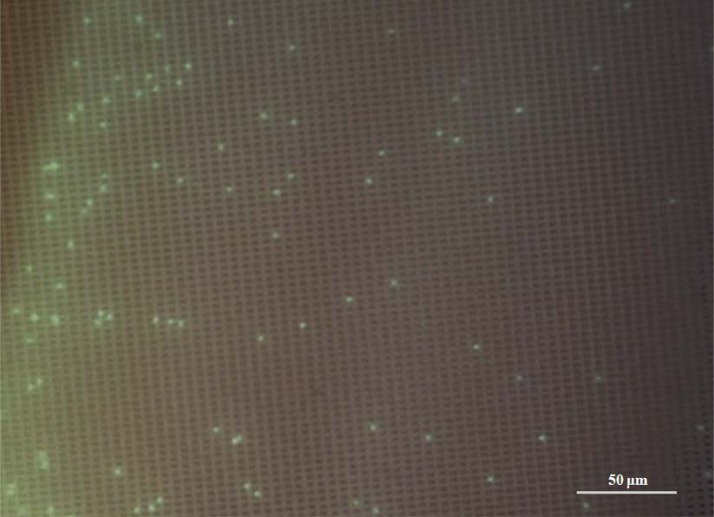
The capturing capability of the multi-layer polymeric filter was verified by a two-step C. parvum oocysts filtration method. In the first step, 10 l of sample, which was pure water (collected from a Millipore purification unit (MilliQ plus)) spiked with 2 × 10³ heat inactivated C. parvum oocysts (Waterborne Inc. New Orleans, LA, USA, Cat. No. P102C@1 × 10⁶) was filtered using a multi-layer polymeric micro-sieve. The filtration was performed in dead-end mode using a peristaltic pump at a flow rate of 2 l min−1. Upon completion of filtration, containers were rinsed with 2 l of pure water that were additionally filtered. Then the filtered water goes to a subsequent filtration step using an Anodisc membrane (Whatman, Cat. No. 6809-5522) with nominal pore size of 0.2 μm to capture any oocyst that may pass through the multi-layer polymeric micro-sieve. C. parvum oocysts attached to both two filters were observed under a fluorescence microscope by fluorescein iso-thiocyanate (FITC) technique (Waterborne, Inc., New Orleans, LA, USA, Cat. No. A400FLK). Microscopic observations revealed that all the oocysts were captured by the multi-layer polymeric micro-sieve, and no oocyst was found on the second filter (i.e., the Anodisc filter). Figure 7 shows a part of the polymeric micro-sieve after filtration of C. parvum oocysts. The trapped oocysts can be seen on the surface of membrane.
Figure 7.
Fluorescence microscopic image of the trapped C. parvum oocysts on the surfaces of a multi-layer polymeric micro-sieve after filtration of 10 l of sample (pure water spiked with 2 × 10³ heat inactivated C. parvum oocysts).
In order to check the recovery rate, the multi-layer micro-sieve was back-flushed with an appropriate buffer (i.e., 1% sodium polyphosphate (NaPP) and 0.1% Tween 80) to recover the oocysts from the surface. The back-flush was carried out using the peristaltic pump under 0.2 bar pressure for 2 min. The following optical observations of the filter membrane showed that more than 90% ± 5% of C. parvum oocysts were recovered. Unique features of the multi-layer polymeric micro-sieve like the smooth surface and uniform pore-size greatly reduce the oocyst adhesion to the filter surface and enable us to achieve a very high recovery rate in comparison to the available commercial filters for this purpose.23, 24
Reusability and other applications
Commercial micro-filters are not designed to be reusable, and they can hardly retain their initial status after the filtration and recovery process20 (i.e., many cells trap inside their tortuous pore path) while the polymeric multi-layer micro-sieve can easily retain its original condition with a simple back-flushing or lateral shaking. SU-8 also has good chemical properties and can be cleaned using appropriate buffers or chemical like weak acids.25, 26 Hence, a long lifetime and the ability to be cleaned easily make the polymeric multi-layer micro-sieve a good option for the conditions where conventional filters must be replaced regularly.
Unique features of the polymeric multi-layer filter such as smooth surface, straight pore path, high porosity, and identical pore size make it suitable for various applications. For instance, it can be used as a stencil for micro-patterning of cells, bio-molecules and metallic films27 or even can be employed for separation of blood cells (red blood cells (RBCs) and white blood cells (WBCs)) from whole blood for clinical assays.28
CONCLUSION
In the present work, we explained a method for rapid fabrication of polymeric micro-sieves using MEMS techniques. This method can be used to fabricate microporous polymeric micro-sieves with smooth surfaces, narrow pore size distribution, high porosity, and good mechanical strength. By employing this method, we can successfully overcome the resolution limit of negative based photo-resist and make robust polymeric micro-sieves with micron size perforations. Sample loading and back-flushing using the multi-layer micro-sieves resulted in more than 90% recovery of pathogens, which showed improved performance than current commercial filters. The microfiltration tests using tap-water also revealed that the polymeric micro-sieve has a higher throughput than the commercial filters like track-etched membrane filter for the same purpose. The obtained micro-sieves can be used also for other applications like isolation of microorganisms, blood filtration, bioassays, micro-pattering, and cytology.
ACKNOWLEDGMENTS
The authors acknowledge the financial support of the Environment & Water Industry Programme Office of Singapore under the project Grant No. MEWRC651/06/170.
References
- Peskoller C., Niessner R., and Seidel M., Anal. Bioanal. Chem. 393, 399 (2009). 10.1007/s00216-008-2381-5 [DOI] [PubMed] [Google Scholar]
- Floriano P. N., Christodoulides N., Romanovicz D., Bernard B., Simmons G. W., Cavell M., and McDevitt J. T., Biosens. Bioelectron. 20, 2079 (2005). 10.1016/j.bios.2004.08.046 [DOI] [PubMed] [Google Scholar]
- Noble R. T. and Weisberg S. B., J. Water Health 3, 381 (2005), http://www.iwaponline.com/jwh/003/jwh0030381.htm. [DOI] [PubMed] [Google Scholar]
- Quintero-Betancourt W., Peele E. R., and Rose J. B., J. Microbiol. Methods 49, 209 (2002). 10.1016/S0167-7012(02)00007-6 [DOI] [PubMed] [Google Scholar]
- Yang L. and Bashir R., Biotechnol. Adv. 26, 135 (2008). 10.1016/j.biotechadv.2007.10.003 [DOI] [PubMed] [Google Scholar]
- Dubitsky A., DeCollibus D., and Ortolano G. A., J. Biochem. Biophys. Methods 51, 47 (2002). 10.1016/S0165-022X(01)00243-3 [DOI] [PubMed] [Google Scholar]
- Wohlsen T., Bates J., Gray B., and Katouli M., Appl. Environ. Microbiol. 70, 2318 (2004). 10.1128/AEM.70.4.2318-2322.2004 [DOI] [PMC free article] [PubMed] [Google Scholar]
- Kuiper S., Van Rijn C. J. M., Nijdam W., and Elwenspoek M. C., J. Membr. Sci. 150, 1 (1998). 10.1016/S0376-7388(98)00197-5 [DOI] [Google Scholar]
- Rijn C. J. M., Veldhuis G. J., and Kuiper S., Nanotechnology 9, 343 (1998). 10.1088/0957-4484/9/4/007 [DOI] [Google Scholar]
- Han K., Xu W., Ruiz A., Ruchhoeft P., and Chellam S., J. Membr. Sci. 249, 193 (2005). 10.1016/j.memsci.2004.09.044 [DOI] [Google Scholar]
- Yanagishita T., Nishio K., and Masuda H., J. Vac. Sci. Technol. B 25, L35 (2007). 10.1116/1.2753847 [DOI] [Google Scholar]
- Saxena I., Agrawal A., and Joshi S. S., J. Micromech. Microeng. 19, 025025 (2009). 10.1088/0960-1317/19/2/025025 [DOI] [Google Scholar]
- Gironès M., Akbarsyah I. J., Nijdam W., Van Rijn C. J. M., Jansen H. V., Lammertink R. G. H., and Wessling M., J. Membr. Sci. 283, 411 (2006). 10.1016/j.memsci.2006.07.016 [DOI] [Google Scholar]
- Chen L., Warkiani M. E., Liu H. B., and Gong H. Q., J. Micromech. Microeng. 20, 075005 (2010). 10.1088/0960-1317/20/7/075005 [DOI] [Google Scholar]
- Campo A. and Greiner C., J. Micromech. Microeng. 17, R81 (2007). 10.1088/0960-1317/17/6/R01 [DOI] [Google Scholar]
- Mata A., Fleischman A., and Roy S., J. Micromech. Microeng. 16, 276 (2006). 10.1088/0960-1317/16/2/012 [DOI] [Google Scholar]
- Kim K., Park D. S., Lu H. M., Che W., Lee J. B., and Ahn C. H., J. Micromech. Microeng. 14, 597 (2004). 10.1088/0960-1317/14/4/021 [DOI] [Google Scholar]
- Chang Y. J., Mohseni K., and Bright V. M., Sens. Actuators, A 136(2), 546 (2007). 10.1016/j.sna.2007.01.009 [DOI] [Google Scholar]
- Lin C., Lee G., Chang B., and Chang G., J. Micromech. Microeng. 12, 590 (2002). 10.1088/0960-1317/12/5/312 [DOI] [Google Scholar]
- Warkiani M. E., Chen L., Lou C. P., Liu H. B., Zhang R., and Gong H. Q., J. Membr. Sci. 369, 560 (2011). 10.1016/j.memsci.2010.12.038 [DOI] [Google Scholar]
- Voskerician G., Shive M. S., Shawgo R. S., Von Recum H., Anderson J. M., Cima M. J., and Langer R., Biomaterials 24, 1959 (2003). 10.1016/S0142-9612(02)00565-3 [DOI] [PubMed] [Google Scholar]
- Ramachandran V. and Fogler H. S., J. Fluid Mech. 385, 129 (1999). 10.1017/S0022112098004121 [DOI] [Google Scholar]
- Karim H., Sylvain S., Laurence L., Lucien H., and Henry-Michel C., Water Sci. Technol. 62(1), 196 (2010). 10.2166/wst.2010.311 [DOI] [PubMed] [Google Scholar]
- Nieminski E. C., F.Schaefer3rd, and Ongerth J. E., Appl. Environ. Microbiol. 61(5), 1714 (1995), http://aem.asm.org/cgi/content/abstract/61/5/1714. [DOI] [PMC free article] [PubMed] [Google Scholar]
- van Rijn C. J. M., Nano and Micro Engineered Membrane Technology (Elsevier, Amsterdam, 2004), Vol. 10. [Google Scholar]
- Becker H. and Locascio L. E., Talanta 56(2), 267 (2002). 10.1016/S0039-9140(01)00594-X [DOI] [PubMed] [Google Scholar]
- Wright D., Rajalingam B., Kar J., Selvarasah S., Ling Y., Yeh J., Langer R., Dokmeci M., and Khademhosseini A., J. Biomed. Mater. Res. Part A 85, 530 (2008). 10.1002/jbm.a.v85a:2 [DOI] [PMC free article] [PubMed] [Google Scholar]
- Li J., Liu C., Dai X., Chen H., Liang Y., Sun H., Tian H., and Ding X., J. Micromech. Microeng. 18, 095021 (2008). 10.1088/0960-1317/18/9/095021 [DOI] [Google Scholar]


