Abstract
We demonstrate the generation of water-in-water (w/w) jets and emulsions by combining droplet microfluidics and aqueous two-phase systems (ATPS). The application of ATPS in microfluidics has been hampered by the low interfacial tension between typical aqueous phases. The low tension makes it difficult to form w/w droplets with conventional droplet microfluidic approaches. We show that by mechanically perturbing a stable w/w jet, w/w emulsions can be prepared in a controlled and reproducible fashion. We also characterize the encapsulation ability of w/w emulsions and demonstrate that their encapsulation efficiency can be significantly enhanced by inducing formation of precipitates and gels at the w/w interfaces. Our work suggests a biologically and environmentally friendly platform for droplet microfluidics and establishes the potential of w/w droplet microfluidics for encapsulation-related applications.
INTRODUCTION
Droplet microfluidics has become an important technique in the study of soft condensed matter for the creation of droplets and functional structures such as particles. Advances in droplet microfluidics have enabled the generation of emulsions of complex geometry with a high degree of control over drop size and uniformity as well as with improved encapsulation efficiencies.1, 2 These have led to a plethora of novel approaches for fabricating functional materials,3, 4 which includes microgel particles,5, 6, 7, 8, 9 liposomes,10, 11, 12, 13 polymersomes,14, 15, 16, 17, 18 and colloidosomes.9, 19, 20 Most of these approaches involve the use of emulsion drops as templates and these emulsions contain at least one organic solvent as one of the emulsion phases. Droplet microfluidics also has enormous potential in many biological and pharmaceutical applications due to the high level of control as well as the ability to fabricate structures with complexity similar to that exhibited by biological environments.
In the field of green chemistry, immiscible water-based solutions have been used for alleviating harmful effects to the environment and allaying environmental concerns21 in applications, such as solvent extraction where selected species, for instance, metal ion complexes22 and ruthenium red,23 are separated. These so-called aqueous two-phase systems (ATPS) can form when two chemically dissimilar polymers or a polymer and a salt are mixed in water at sufficiently high concentrations.24, 25 The solutions generally demix into regions enriched in the first polymer and regions enriched in the second polymer or salt. Emulsions formed from the resultant systems are often referred to as water-in-water emulsions (or w/w emulsions).19
The study of ATPS also has important implications for biology and biomaterials. Since the cytoplasm of biological cells also has between 17 and 35 wt. % macromolecules,26 which could potentially demix, phase separation of ATPS phases has been used to model micro-compartmentalization and budding of biological cells.27 The ATPS platform is particularly useful for applications that require high biocompatibility,28 for example, in the preparation of polymer scaffolds for use in the proximity of body tissues or biologically active factors,29 biomolecule separations and cell fractionation,30, 31 partitioning of cells,32, 33 cell patterning,34 as well as patterning of genetic materials on cells for gene overexpression and RNA interference gene silencing studies.35
Despite the numerous advantages of ATPS, the use of droplet microfluidic techniques to generate w/w emulsions has been limited. One major reason is the extremely low interfacial tension of ATPS,36, 37 which is generally between 10−4 and 10−6 N/m (i.e., 100-1000 times lower than the interfacial tension of typical oil-water interfaces38). The low interfacial tension22, 36, 37 of ATPS leads to a reduction in the driving force for liquid jets to break up into droplets by Rayleigh-Plateau instability. To direct the jets to form droplets, external forcing, for instance, periodic disturbance of the jet through the use of piezoelectric devices, is needed.37, 39 Alternatively, this could done through efficient valve closure using multi-level microchannels.40 These examples have demonstrated the viability of generating w/w emulsions by modifying established microfluidic devices. However, it remains difficult to achieve controlled emulsification of two aqueous phases without significant alteration to the devices. In addition, to better understand the applicability of these w/w emulsions, the encapsulation efficiency of w/w emulsions, which is a unique advantage of droplet microfluidic techniques, should also be investigated. However, to date, microfluidic fabrication of w/w emulsions and characterization of the resultant w/w emulsions remains inadequately studied.
In this work, we use aqueous two-phase systems (ATPS) to replace conventional water-organic-solvent systems for preparation of water-in-water (w/w) emulsions.22, 31, 36, 37 By perturbing the pressure used to inject the dispersed phase into a glass microcapillary device, monodisperse w/w emulsions can be prepared. The uniformity of droplet sizes produced by this technique is important for the applications of the system. However, the w/w emulsions have poor encapsulation ability, limiting their usefulness for applications requiring the encapsulation of chemical and biological substances within the droplets that are created. This was demonstrated by experiments showing the rapid release of a test molecule from the droplets into the continuous phase. We show that the encapsulation efficiency of the w/w emulsions can be enhanced using two interfacial reaction approaches, namely, interfacial precipitation and interfacial gelation. By introducing mechanical shaking to the system to facilitate jet breakup and droplet formation, we demonstrate a simple approach that can be applied in many existing systems with only small modifications. This allows the technique to be easily adopted to well-established devices so that the encapsulation methods we demonstrate for w/w emulsions can be easily implemented.
EXPERIMENTAL SECTION
Materials
Poly(ethylene glycol) (PEG, Sigma-Aldrich, Mw 8000), Poly(ethylene glycol)-diacrylate (PEG-DA, Sigma-Aldrich), dextran (Spectrum, Mw 500 000), tripotassium phosphate (K3PO4, Baker), and dipotassium phosphate (K2HPO4, Mallinckrodt) were used as the additives for forming the ATPS phases. Calcium chloride (Sigma-Aldrich), sodium carbonate (Sigma-Aldrich), and sodium alginate sodium salt (Fluka) were used for the interfacial precipitation and gelation reactions. Allura Red (Sigma-Aldrich) was used as the model actives for encapsulation.
Formation of polydisperse w/w emulsion by shaking: To confirm the formation of two immiscible aqueous phases, several two-phase aqueous systems were examined, namely, PEG/Dextran, PEG-DA/Dextran, PEG/K3PO4, and PEG-DA/K3PO4. In each run, we filled glass vials with equal volumes of two corresponding aqueous phases at certain concentrations; the mixtures were then allowed to sit overnight. Afterwards, the vials were lightly shaken to create an emulsion, which was observed on a glass slide to confirm droplet formation.
Microfluidics
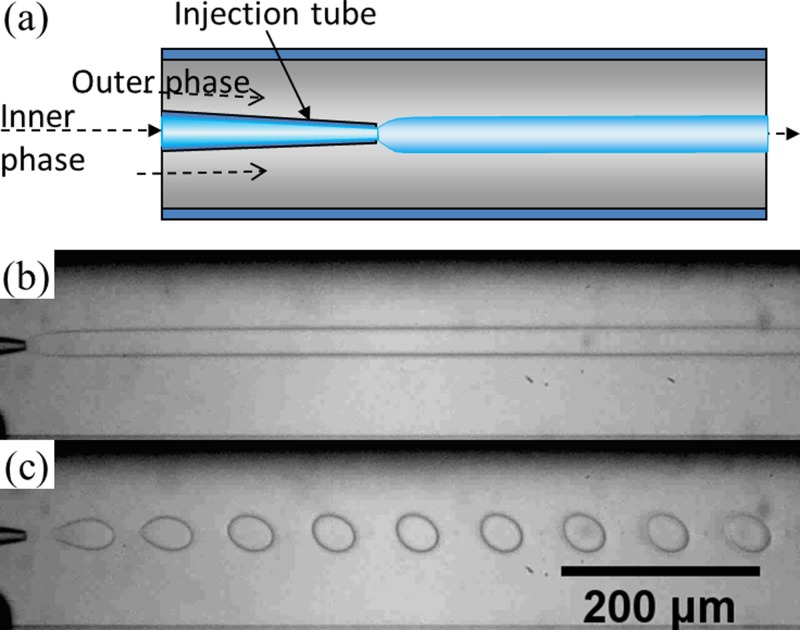
The w/w jets and emulsions were prepared using glass-capillary-based microfluidic devices.1, 41 The round capillary (World Precision Instruments, Inc., Sarasota, Florida), with inner and outer diameters of 0.58 mm and 1.0 mm, respectively, were tapered to desired diameters with a micropipette puller (P-97, Sutter Instrument, Inc.) and a microforge (Narishige International USA, Inc., East Meadow, New York, USA). The round capillary is inserted inside a square glass capillary (Atlantic International Technology, Inc., Rockaway, New Jersey, USA) with an inner dimension of 1.05 mm. Where necessary, the capillaries were sealed using a transparent epoxy resin (5 min Epoxy, Devcon, Danvers, Massachusetts, USA). A schematic and a photograph of the devices are shown in Fig. 1a and Fig. S1 (Ref. 42) in the supporting information, respectively. The ATPS dispersed and continuous phases were injected into the devices at desired flow rates using positive syringe pumps (PHD 2000 series, Harvard Apparatus, Holliston, Massachusetts, USA). A typical set of flow rates for the dispersed and continuous phases was 50 μL/h and 5000 μL/h, respectively. To induce droplet formation, mechanical shaking was applied to the tubing of the dispersed phase by attaching it to an orbital shaker (VWR Symphony, USA), as a simple alternative to piezoelectric oscillations.37, 39 A schematic illustrating the setup for shaking the tubing is shown in Fig. S2 (Ref. 42) in the supporting information. The frequency of the shaker was tuned to perturb the jet for formation of monodisperse w/w emulsion drops. The amplitude of the shaking was constant throughout all trials, as determined by the motion of the orbital shaker, and the direction of the shaking was not controlled. The shaking consisted of a combination of transverse and longitudinal motion to the tubing. The resultant droplets were collected by allowing the outlet tubing to flow gently and directly into a container filled with the continuous phase. With this simple droplet collection method, unstabilized droplets are stable for at least several minutes.
Figure 1.
(a) Schematic of a capillary microfluidic device used in this study; (b) optical microscope image showing a jet of 17 wt. % PEG solution in a continuous phase of 16 wt. % dextran solution in the microfluidic device. Flow rates of the PEG solution and the dextran solution are 40 μl/h and 5000 μl/h, respectively; (c) optical microscope image of monodisperse droplets of 17 wt. % PEG solution in 16 wt. % dextran solution with an agitation of the tubing of the dispersed phase at 6.7 Hz. Flow rates of the two phases are the same as those for (b).
Sample characterization
The microfluidic process was monitored using an inverted optical microscope (DM-IRB, Leica) fitted with a high-speed camera (Phantom V9, V7, V5, Vision Research, Inc.). Bright-field images were obtained at room temperature using an inverted microscope (AE31, Motic, Inc.) equipped with a charge-coupled device (CCD) color camera (Exwave HAD, Sony).
RESULTS AND DISCUSSION
We inject two aqueous phases as dispersed and continuous phases into the glass microcapillary devices. In this work, we mainly choose the aqueous two-phase system of 17 wt. % PEG solution and 16 wt. % dextran solution. The two solutions are first mixed in bulk to ensure phase separation and formation of interfaces between the solutions. Phase separation of the two solutions is believed to occur because of the relative hydrophobicity of the two polymers when mixed in water. Dextran contains many polar hydroxyl groups along the polymer chains, which associate closely with surrounding water molecules and create regions densely populated by water molecules while the less polar PEG has more exposed hydrocarbon components along the backbone. Indeed, when the PEG solution exits the injection tube and meets the dextran solution, a long jet of PEG solution is formed, as shown in Fig. 1b, where the size of the jet depends on the relative flow rates of the inner and outer phases due to the shear that the outer phase imparts on the inner phase. The low interfacial tension of the systems, which is about 0.1 mN/m, does not favor droplet formation significantly. While this is useful for forming water-based fibers in aqueous solution, the low interfacial tension renders it difficult to prepare droplets or emulsion-templated particles and capsules. To induce controlled droplet formation, mechanical shaking is introduced into the system by shaking the tubing; experimentally, it is determined that the jet can be more effectively perturbed by shaking the tubing through which the dispersed phase is injected, rather than the tubing for the continuous phase or the emulsion product phase. Therefore, we introduce perturbation of the jet through mechanically shaking the tubing for injecting the dispersed phase. This shaking provides small pulses in the jet and leads to controlled droplet formation. The size of the droplets depends on the relative flow rates of the inner and outer phases as well as the appropriate shaking frequency, as shown in Fig. 1c. The reproducibility of a system depends specifically on the consistency of the experiment conditions, including concentrations of polymers in the fluid phases, the flow rates of the fluids, and the shaking frequency. The current setup provides little control over the shaking amplitude and direction of the applied shaking; as a result, changing the amplitude and direction shows no observable effects on droplet formation.
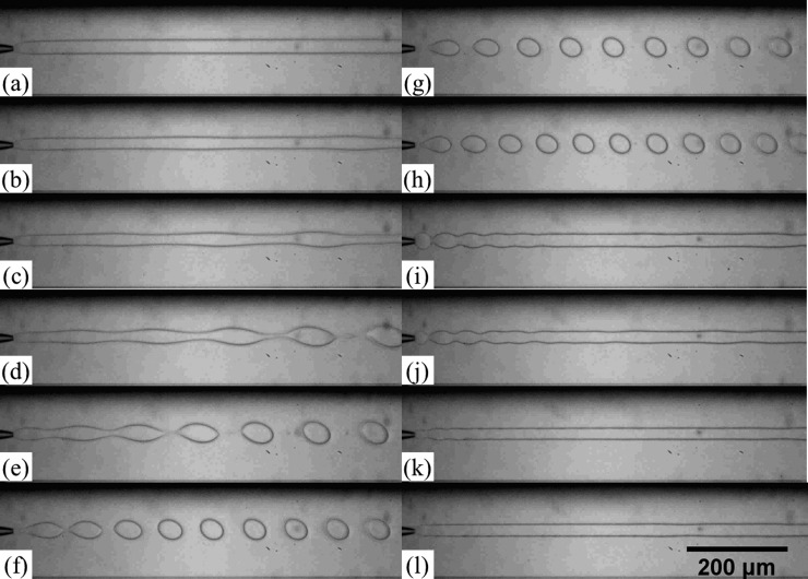
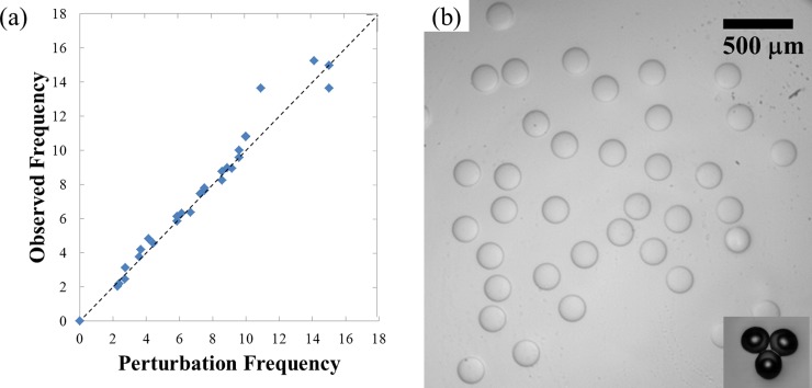
To understand the effect of shaking on the dynamics of the jet, the stable jet is perturbed at different frequencies. At relatively low frequencies (0-5 Hz), the jet is only slightly perturbed with a visible oscillation at the interface of the jet, which remains relatively stable, as shown in Figs. 2a, 2b, 2c, 2d. The observed oscillation is directly driven by the perturbation applied to the dispersed phase, as confirmed by the matching of the observed oscillation frequency with the applied perturbation frequency in the plot in Fig. 3a. As the frequency increases, the jet responds more significantly to the pulses (Fig. 2e); monodisperse droplets are generated when the jet is perturbed at frequencies ranging from 6.2 Hz to 7.5 Hz, as shown in Figs. 2f, 2g, 2h. At high frequencies (10-20 Hz), the jet appears to be perturbed at a higher frequency than the natural frequency of droplet formation (Figs. 2i, 2j, 2k). Therefore, the initial applied perturbation does not grow and no instability is triggered. Based on these observations, we believe that the applied perturbation only provides the initial trigger needed for capillary instability to kick in for droplet formation. Based on the theory of Rayleigh-Plateau instability, the growth rate of the instability will drop to zero at frequencies slightly above the optimal frequency. Experimentally, the perturbations caused by the shaking appear to be too closely spaced with the subsequent pulses; this suggests that the growth rate of the perturbation is too low to result in droplet formation. This is in agreement with other works on induced droplet formation.37
Figure 2.
Optical microscope images showing generation of jets and droplets at different frequency of shaking. The dispersed and continuous phases are 17 wt. % PEG solution and 16 wt. % dextran solution, respectively. Flow rates of the PEG solution and the dextran solution are 40 μl/h and 5000 μl/h, respectively. Applied shaking frequencies are (a) 0 Hz, (b) 2.3 Hz, (c) 2.8 Hz, (d) 3.6 Hz, (e) 4.4 Hz, (f) 6.2 Hz, (g) 6.7 Hz, (h) 7.5 Hz, (i) 9.6 Hz, (j) 10.9 Hz, (k) 15 Hz, and (l) 21 Hz.
Figure 3.
(a) A plot of the observed oscillation frequency in a jet as a function of the applied shaking frequency. The observed oscillation frequency is measured by dividing the number of pulses observed inside the device by the elapsed time between fast camera frames. The applied shaking frequency is indicated by the orbital shaker. (b) Optical microscope image of monodisperse water-in-water (w/w) emulsion droplets of 17 wt. % PEG solution in 16 wt. % dextran solution. Inset: optical microscope image of photo-crosslinked PEG-DA particles generated using an ATPS.
With shaking frequency of roughly 6-8 Hz, monodisperse w/w emulsion droplets are prepared, as shown in Fig. 3b. These droplets destabilize by coalescing with each other in the absence of an appropriate emulsifier. In addition, shrinkage of the droplets was also observed as water flowed out from the dispersed phase into the continuous phase; this was caused by the concentration gradient that existed between the two phases. For the emulsion droplets to be useful, they have to be stable for long enough before droplet coalescence and deformation due to water diffusion. By allowing the phases to mix and separate before being used in the device, the concentration difference can be minimized, leading to stable droplet formation with minimal deformation. Apart from the system of PEG/dextran, microfluidic emulsification can also be applied to other ATPS, such as PEG-DA/dextran and PEG/K3PO4. If PEG-DA is used as the dispersed phase, instead of PEG, the resultant droplets can be photo-crosslinked to form monodisperse microgel particles, as shown in the inset of Fig. 3b.
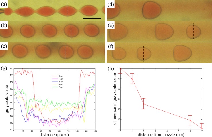
An important characteristic of droplet microfluidic technique lies in the ease in encapsulation of active ingredients and the excellent encapsulation efficiency. For w/w emulsions, since both the dispersed and continuous phases are of aqueous nature, hydrophilic actives may diffuse out of the w/w emulsion droplets, compromising the encapsulation efficiency afforded by droplet microfluidics. To test the encapsulation capabilities of the microfluidic w/w emulsions, we dissolve allura red, a model actives for use with encapsulation, in the dispersed phase of the emulsion. Initially, the droplets generated at the tip of the capillary microfluidic device contain the dye without leakage to the continuous phase (Fig. 4a). However, as the droplets flow downstream, the dye quickly diffuses out of the droplets, as shown in Fig. 4. The net diffusion of the dye from the inside to the outside of the droplets is expected due to the gradient in the dye concentration. This is highlighted by the reduction in the intensity difference between the inside and the outside of the droplets as they flow downstream, as demonstrated by the grayscale profile across droplets imaged at different distances from the nozzle in Figs. 4g, 4h. Only about seven centimeters downstream from the tip of the injection tube, a significant fraction of the dye has diffused out of the droplets, as confirmed by the reduction in the color intensity in the droplets and the corresponding staining of the continuous phase shown in Figs. 4g, 4h. The rapid release of hydrophilic actives out of the droplets limits the potential of microfluidic w/w emulsion droplets for encapsulation-related applications.
Figure 4.
Optical microscope images of droplets of water with 17 wt. % PEG solution and 1 wt. % allura red in a continuous phase of 16 wt. % dextran solution observed at (a) 0 cm, (b) 1 cm, (c) 2 cm, (d) 3 cm, (e) 6 cm, and (f) 7 cm from the tip of the injection tip. The reddening of the continuous phase suggests that allura red in the droplets gradually diffuses into the continuous phase. Scale bar is 200 μm. (g) Profile of grayscale value across a droplet imaged at 0 cm, 1 cm, 2 cm, 6 cm, and 7 cm from the nozzle. The grayscale value is obtained by converting the color images into grayscale images and subsequently measuring the grayscale value, which indicates the color intensity in the original color images. A smaller grayscale value indicates a higher intensity in the original color image. The dashlines in (a), (b), (c), (d), and (f) indicate the line across which the intensity profiles are obtained in the corresponding images. (h) Plot of the difference in the grayscale value between the inside and the outside of a droplet imaged at different distance from the nozzle.
To improve the encapsulation capability of the w/w emulsion droplets, barriers against diffusion of hydrophilic species out of the droplets are required. To achieve this, we introduce an interfacial precipitation approach where two reactants for a precipitation reaction are added to the dispersed and continuous phase. Thus, precipitates form upon contact of the two reactants at the interface. In our work, we use the precipitation reaction between calcium chloride and sodium carbonate, which are added to the dispersed and continuous phases respectively, as a proof of the concept.
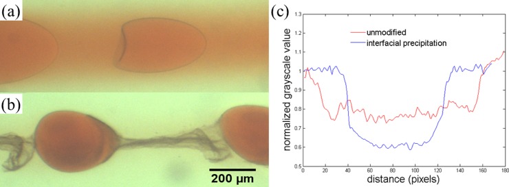
With this interfacial precipitation approach, the correct concentrations of precipitation agents must be used. If the concentrations of calcium chloride and sodium carbonate are too high, a precipitate tube forms around the jet and the perturbations are not able to induce formation of droplets. If the concentrations are too low, the enhancement in encapsulation efficiency will be limited. With appropriate concentrations of precipitation agents, controlled droplets are formed at a limited range of perturbation frequency. With the interfacial precipitation approach, the encapsulation efficiency is indeed improved significantly. The outward diffusion of the dye into the continuous phase is significantly reduced by the precipitates at the interface. The ability of the precipitates in slowing down dye diffusion is demonstrated by the lack of coloring in the continuous phase two centimeters downstream from the tip of the injection tube in Fig. 5. This is in stark contrast with the case without the interfacial precipitation approach. To demonstrate the effectiveness of the approach, we compare droplets imaged at two centimeters from the nozzle with and without interfacial precipitation, as shown in Figs. 6a, 6b. By analyzing the images using image processing tools and obtaining a grayscale profile across the droplets, we observe a higher difference in the normalized grayscale value between the droplet phase and the continuous phase for the system with interfacial precipitation, as shown in Fig. 6c. This confirms the enhanced encapsulation efficiency in droplets with interfacial precipitation.
Figure 5.
Interfacial precipitation for enhancing encapsulation efficiency of allura red. Optical microscope images of (a)-(c) jets and (d) droplets of water with 17 wt. % PEG and 1 wt. % calcium chloride in a continuous phase of water with 16 wt. % dextran and 1 wt. % sodium carbonate. Images (a) and (c) are taken at 0.5 cm from the tip of the injection capillary while images (b) and (d) show the same jets as in (a) and (c), respectively, at 2 cm from the tip of the injection capillary. Shaking is only applied to the jet shown in (c) and (d). The calcium ions and the carbonate ions in the dispersed and continuous phases, respectively, react to form a precipitate of calcium carbonate. In (d), the satellite drops form between two larger parent drops since the addition of components for interfacial precipitation modifies the rheological properties of the fluids. Scale bar is 1 mm.
Figure 6.
Interfacial precipitation for enhancing the encapsulation efficiency of allura red viewed as an optical microscope image of a system of 16 wt. % dextran in the continuous phase and 17 wt. % PEG 8000 in the dispersed phase (a) with no encapsulation and (b) with encapsulation using 2 wt. % CaCl2 in the dispersed phase and 2 wt. % Na2CO3 in the continuous phase (flow rates: 5000 μl/h for continuous phase and 100 μl/h for dispersed phase). (c) Profile of normalized grayscale value across a droplet with and without interfacial precipitation imaged at 2 cm from the nozzle. The normalized grayscale value is obtained by converting the color images into grayscale images and subsequently measuring the grayscale value, which indicates the color intensity in the original color images. The resultant values are normalized by the average grayscale value obtained in the continuous phase. A smaller grayscale value indicates a higher intensity in the original color image. The higher difference in the normalized grayscale value between the droplet phase and the continuous phase for the system with interfacial precipitation indicates an enhanced encapsulation efficiency.
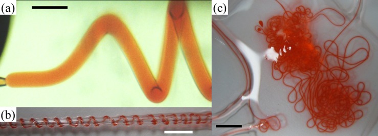
Apart from the interfacial precipitation approach, we also apply an interfacial gelation approach to enhance the encapsulation ability of w/w emulsions and ATPS-based fibers prepared using microfluidics. We prepare ATPS fibers by mixing calcium chloride and alginic acid in the dispersed phase of PEG solution and the continuous phase of dextran solution, respectively. Upon contact of the two phases, the alginic acid and calcium chloride react to form a calcium alginate gel fiber, as shown in Fig. 7. The allura red remains encapsulated in the jet and the resultant fiber without significant leakage into the continuous phase inside the device. These biocompatible actives-encapsulating fibers are of interest to biomedical and tissue engineering applications. However, due to the significant increase in the viscosity and the non-Newtonian rheological properties of the precursor solutions for interfacial gelation, perturbations exerted with the current setup are insufficient to induce controlled droplet breakup. Only uncontrolled droplets are observed for a certain limited range of concentrations of alginic acid and calcium chloride. Despite the difficulty in forming droplets with the present setup, the concept of enhanced encapsulation of model actives by interfacial gelation is demonstrated in the fibers; the concept should be equally applicable to droplets. Our works suggest that the advantage of high encapsulation efficiency afforded by microfluidic techniques can be retained in w/w systems.
Figure 7.
Gelation for enhancing the encapsulation efficiency of allura red. (a) Optical microscope image of a jet of water with 17 wt. % PEG, 1 wt. % allura red and 2 wt. % calcium chloride in a continuous phase of water with 16 wt. % dextran and 1 wt. % alginic acid. Scale bar is 800 μm; (b) and (c) Digital photographs of calcium alginate gel fibers encapsulating allura red prepared using two water-based phases in a capillary microfluidic device. Scale bars are 5 mm and 15 mm in (b) and (c), respectively.
CONCLUSION
We demonstrate the generation of water-in-water (w/w) jets and emulsions by combining droplet microfluidics and aqueous two-phase systems (ATPS). By mechanically perturbing a stable w/w jet, w/w emulsions can be prepared in a controlled and reproducible fashion. We also show that despite the poor encapsulation ability of the w/w jets and emulsions, the interfaces of the w/w systems can be modified by inducing formation of precipitates and gels at the w/w interfaces. In comparison to the traditional combinations of water and organic solvents, the additives for forming ATPS are relatively harmless, and the aqueous environment can support more fragile contents than water/solvent systems. Moreover, the use of these ATPS has also been recognized as a more environmentally friendly and so-called green alternative to water/solvent systems. Thus, our work represents an important step towards a green and biocompatible droplet microfluidic platform. With the approach of perturbation-induced droplet breakup, it should be possible to tune droplet size by changing the frequency of perturbation and relative flow rates. This would further enhance the degree of control afforded by droplet microfluidics.
ACKNOWLEDGMENTS
This work was supported by the NSF (DMR-1006546), the Harvard MRSEC (DMR-0820484), and the Seed Funding Programme for Basic Research from the University of Hong Kong (201101159009).
References
- Shah R. K., Shum H. C., Rowat A. C., Lee D., Agresti J. J., Utada A. S., Chu L.-Y., Kim J.-W., Fernandez-Nieves A., Martinez C. J., and Weitz D. A., Mater. Today 11(4), 18 (2008). 10.1016/S1369-7021(08)70053-1 [DOI] [Google Scholar]
- Teh S. Y., Lin R., Hung L. H., and Lee A. P., Lab Chip 8(2), 198 (2008). 10.1039/b715524g [DOI] [PubMed] [Google Scholar]
- Shum H. C., Abate A. R., Lee D., Studart A. R., Wang B. G., Chen C. H., Thiele J., Shah R. K., Krummel A., and Weitz D. A., Macromol. Rapid Commun. 31(2), 108 (2010). 10.1002/marc.200900590 [DOI] [PubMed] [Google Scholar]
- Anna S. L., Bontoux N., and Stone H. A., Appl. Phys. Lett. 82(3), 364 (2003). 10.1063/1.1537519 [DOI] [Google Scholar]
- Zhang H., Tumarkin E., Peerani R., Nie Z., Sullan R. M. A., Walker G. C., and Kumacheva E., J. Am. Chem. Soc. 128(37), 12205 (2006). 10.1021/ja0635682 [DOI] [PubMed] [Google Scholar]
- Panda P., Ali S., Lo E., Chung B. G., Hatton T. A., Khademhosseini A., and Doyle P. S., Lab Chip 8(7), 1056 (2008). 10.1039/b804234a [DOI] [PMC free article] [PubMed] [Google Scholar]
- Hwang D. K., Oakey J., Toner M., Arthur J. A., Anseth K. S., Lee S., Zeiger A., Vliet K. J. V., and Doyle P. S., J. Am. Chem. Soc. 131(12), 4499 (2009). 10.1021/ja809256d [DOI] [PMC free article] [PubMed] [Google Scholar]
- Seiffert S., Thiele J., Abate A. R., and Weitz D. A., J. Am. Chem. Soc. 132(18), 6606 (2010). 10.1021/ja102156h [DOI] [PubMed] [Google Scholar]
- Shah R. K., Kim J. W., and Weitz D. A., Langmuir 26(3), 1561 (2010). 10.1021/la9041327 [DOI] [PubMed] [Google Scholar]
- Shum H. C., Lee D., Yoon I., Kodger T., and Weitz D. A., Langmuir 24(15), 7651 (2008). 10.1021/la801833a [DOI] [PubMed] [Google Scholar]
- Jahn A., Vreeland W. N., DeVoe D. L., Locascio L. E., and Gaitan M., Langmuir 23(11), 6289 (2007). 10.1021/la070051a [DOI] [PubMed] [Google Scholar]
- Tan Y. C., Hettiarachchi K., Siu M., and Pan Y. P., J. Am. Chem. Soc. 128(17), 5656 (2006). 10.1021/ja056641h [DOI] [PubMed] [Google Scholar]
- Stachowiak J. C., Richmond D. L., Li T. H., Liu A. P., Parekh S. H., and Fletcher D. A., Proc. Natl. Acad. Sci. U.S.A. 105(12), 4697 (2008). 10.1073/pnas.0710875105 [DOI] [PMC free article] [PubMed] [Google Scholar]
- Shum H. C., Kim J. W., and Weitz D. A., J. Am. Chem. Soc. 130(29), 9543 (2008). 10.1021/ja802157y [DOI] [PubMed] [Google Scholar]
- Brown L., McArthur S. L., Wright P. C., Lewis A., and Battaglia G., Lab Chip 10(15), 1922 (2010). 10.1039/c004036c [DOI] [PubMed] [Google Scholar]
- Shum H. C., Santanach-Carreras E., Kim J. W., Ehrlicher A., Bibette J., and Weitz D. A., J. Am. Chem. Soc. 133(12), 4420 (2011). 10.1021/ja108673h [DOI] [PMC free article] [PubMed] [Google Scholar]
- Shum H. C., Zhao Y. J., Kim S. H., and Weitz D. A., Angew. Chem., Int. Ed. 50(7), 1648 (2011). 10.1002/anie.201006023 [DOI] [PubMed] [Google Scholar]
- Perro A., Nicolet C., Angy J., Lecommandoux S., Le Meins J. F., and Colin A., Langmuir 27(14), 9034 (2011). 10.1021/la1037102 [DOI] [PubMed] [Google Scholar]
- Poortinga A. T., Langmuir 24(5), 1644 (2008). 10.1021/la703441e [DOI] [PubMed] [Google Scholar]
- Sander J. S. S. J. S. and Studart A. R., Langmuir 27(7), 3301–3307 (2011). 10.1021/la1035344 [DOI] [PubMed] [Google Scholar]
- Chen J., Spear S. K., Huddleston J. G., and Rogers R. D., Green Chem. 7(2), 64 (2005). 10.1039/b413546f [DOI] [Google Scholar]
- Song Y. S., Choi Y. H., and Kim D. H., J. Chromatogr. A 1162(2), 180 (2007). 10.1016/j.chroma.2007.06.032 [DOI] [PubMed] [Google Scholar]
- Choi Y. H., Song Y. S., and Kim D. H., J. Chromatogr. A 1217(24), 3723 (2010). 10.1016/j.chroma.2010.04.015 [DOI] [PubMed] [Google Scholar]
- Cans A. S., Andes-Koback M., and Keating C. D., J. Am. Chem. Soc. 130(23), 7400 (2008). 10.1021/ja710746d [DOI] [PubMed] [Google Scholar]
- Albertsson P. Å., Partition of Cell Particles and Macromolecules: Separation and Purification of Biomolecules, Cell Organelles, Membranes, and Cells in Aqueous Polymer Two-Phase Systems and Their Use in Biochemical Analysis and Biotechnology, 3rd ed. (Wiley, New York, 1986). [Google Scholar]
- Fulton A. B., Cell 30(2), 345 (1982). 10.1016/0092-8674(82)90231-8 [DOI] [PubMed] [Google Scholar]
- Pagliaro L., in International Review of Cytology, edited by Walter D. E. B. H. and Paul A. S. (Academic Press, Waltham, Massachusetts, 1999), Vol. 192, pp. 303–318. [Google Scholar]
- Andrews B. A., Schmidt A. S., and Asenjo J. A., Biotechnol. Bioeng. 90(3), 380 (2005). 10.1002/bit.v90:3 [DOI] [PubMed] [Google Scholar]
- Woods H. M., Silva M. M. C. G., Nouvel C., Shakesheff K. M., and Howdle S. M., J. Mater. Chem. 14(11), 1663 (2004). 10.1039/b315262f [DOI] [Google Scholar]
- Helfrich M. R., Mangeney-Slavin L. K., Long M. S., Djoko Y., and Keating C. D., J. Am. Chem. Soc. 124(45), 13374 (2002). 10.1021/ja028157+ [DOI] [PubMed] [Google Scholar]
- Albertsson P. A., Trends Biochem. Sci. 3(2), N37 (1978). [Google Scholar]
- Yamada M., Kasim V., Nakashima M., Edahiro J., and Seki M., Biotechnol. Bioeng. 88(4), 489 (2004). 10.1002/bit.v88:4 [DOI] [PubMed] [Google Scholar]
- Nam K. H., Chang W. J., Hong H., Lim S. M., Kim D. I., and Koo Y. M., Biomed. Microdevices 7(3), 189 (2005). 10.1007/s10544-005-3025-6 [DOI] [PubMed] [Google Scholar]
- Tavana H., Mosadegh B., and Takayama S., Adv. Mater. 22(24), 2628 (2010). 10.1002/adma.200904271 [DOI] [PMC free article] [PubMed] [Google Scholar]
- Tavana H., Jovic A., Mosadegh B., Lee Q. Y., Liu X., Luker K. E., Luker G. D., Weiss S. J., and Takayama S., Nature Mater. 8(9), 736 (2009). 10.1038/nmat2515 [DOI] [PMC free article] [PubMed] [Google Scholar]
- Diamond A. D. and Hsu J. T., AIChE J. 36(7), 1017 (1990). 10.1002/aic.v36:7 [DOI] [Google Scholar]
- Ziemecka I., van Steijn V., Koper G. J. M., Rosso M., Brizard A. M., van Esch J. H., and Kreutzer M. T., Lab Chip 11(4), 620 (2011). 10.1039/c0lc00375a [DOI] [PubMed] [Google Scholar]
- Scholten E., Tuinier R., Tromp R. H., and Lekkerkerker H. N. W., Langmuir 18(6), 2234 (2002). 10.1021/la0114373 [DOI] [Google Scholar]
- Rohani M., Jabbari F., and Dunn-Rankin D., Phys. Fluids 22(10), 107103 (2010). 10.1063/1.3494610 [DOI] [Google Scholar]
- Lai D., Frampton J. P., Sriram H., and Takayama S., Lab Chip 11(20), 3551 (2011). 10.1039/c1lc20560a [DOI] [PubMed] [Google Scholar]
- Utada A. S., Lorenceau E., Link D. R., Kaplan P. D., Stone H. A., and Weitz D. A., Science 308(5721), 537 (2005). 10.1126/science.1109164 [DOI] [PubMed] [Google Scholar]
- See supplementary material at http://dx.doi.org/10.1063/1.3670365 for an image of the glass capillary device and a schematic illustrating how shaking is applied to the dispersed phase.


