Abstract
Here, we present a microfluidic droplet trap that takes advantage of the net Laplace pressure force generated when a droplet is differentially constricted. Mathematical simulations were first used to understand the working range of the component; followed by finite element modeling using the CFD software package to further characterize the behavior of the system. Controlled release of the trapped droplets is also demonstrated through both a mechanical method and a chemical method that manipulates the total pressure exerted on the trapped droplet. The unique design of this trapping device also provides the capability for selection of a single droplet from a train, as well as droplet fusion.
INTRODUCTION AND BACKGROUND
Droplets of nanoliter and picoliter volume serve as effective reaction vessels for observation of microscale chemical and biological events, owing to their small volume which ensures rapid mixing, heat transfer and low consumption of reagents. They are particularly ideal for applications such as single-cell analysis, since the contents of a cell do not become heavily diluted within the small volume.1 For applications such as real-time polymerase chain reaction (PCR), it is often necessary or desirable to monitor the progress of a reaction over time. Therefore, the ability to hold droplets in place to enable continuous interrogation is critical. Droplet traps employing various means of confinement, such as optical traps2 or tweezers,3 Marangoni traps using heat gradients,4 electrowetting,5 and dielectrophoresis6 have been demonstrated. Although these techniques allow for a very high level of precision in the manipulation of a single droplet, the throughput of these systems is low and the trapping mechanism requires active controls. Several designs for trapping an array of droplets have been published,7, 8, 9 but in these designs it is difficult to selectively release an individual droplet from an array. Wang et al. developed a device where an applied DC field could be used to draw a droplet from the main fluidic channel into a side compartment. The design could be arrayed, so that many such traps would be available for holding droplets, but in this design, each trap would need its own pair of electrodes to control the trapping.7 In the Dropspots array by Schmitz et al., features on the surface of the microfluidic device contain a train of droplets for on-chip storage. Although the droplets can be released on demand, the design necessitates that all droplets be released from the array at once—it is not possible to remove a single droplet from the array.8 In addition, many published droplet trapping geometries are only compatible with droplets of a certain size. Boukellal et al. demonstrated a device for trapping and storage of droplets, but the geometry of this device requires droplets within a certain size range for successful operation of the device.9 The device presented here is unique in that it may be tuned to accommodate a wide variety of droplet sizes as well as different fluids.
Here, a microfluidic device to reliably and passively trap droplets is demonstrated. The trapping mechanism functions by balancing the net Laplace pressure exerted on the droplet by the front and back curved surface and the hydrostatic pressure exerted on the droplet by the flowing continuous phase. The trapping mechanism was studied utilizing simulations to explore the relationship betwen physical parameters and droplet trapping effectiveness. We then examined the release of droplets from the trap utilizing two different methods to disturb the pressure balance. It was found that the trapped droplet can be reliably released from the trap using mechanical or chemical means. The hydrostatic pressure could be increased by means of actuating a mechanical valve, which increased the pressure at the back of the droplet enabling the droplet to release from the trap by overcoming the Laplace pressure. The droplet could also be released by decreasing the Laplace pressure at the front of the droplet by increasing the local surfactant concentration and, therefore, decreasing the interfacial tension. The design shows great versatility in its ability to trap and controllably release droplets using different mechanisms. We believe the Laplace trap has potential as a method to temporarily capture a droplet for interrogation with the ability to selectively release the trapped droplet allowing further downstream processing mediated by subsequent traps.
THEORY OF LAPLACE TRAP MECHANISM
The Laplace pressure for a given interface is defined by the Young-Laplace equation,
| (1) |
where γ = the interfacial tension between the two phases and R = the radius of curvature of the interface. The hydrostatic pressure is given for a rectangular channel by the Hagen-Poiseuille equation,
| (2) |
where μ = viscosity of the continuous phase, L = length of the channel over which the pressure drop is calculated, Q = volumetric flow rate of the continuous phase, w = width of the microfluidic channel, and h = height of the microfluidic channel.
An illustration of the direction and location of the forces on a droplet inside the trap is shown in Figure 1. Since the droplet is entering a narrowing channel, the front of the droplet will experience a different Laplace pressure than the back of the droplet due to the changing cross-sectional area of the channel. This difference induces a net force on the droplet as a result of the difference in the radius of curvature between the front and back of the droplet. This impedes the droplet’s forward progress. When this force is balanced by the hydrostatic pressure force applied to the droplet by the continuous phase that is pushing the droplet forward, the droplet will slow down dramatically and eventually stop, as the two forces become equal and opposite to each other.
Figure 1.
(a) The major features of the Laplace trap are shown. (b) Force balance illustrating the direction of the Laplace pressure forces acting across the interfaces of both the front and back of the droplet (black) and hydrostatic pressure forces, supplied by the continuous phase in the microfluidic channels (red). Arrow size shows relative magnitudes of the forces. (c) The axis system for the development of the mathematical model of Laplace pressure forces on a droplet constricted in the trap. Red and blue dashed lines show the radii of curvature for the y (red) and z (blue) directions, which correspond to Ry and Rz in the text.
Considering the case where a droplet is constrained between two infinite plates, representing the height of a microfluidic channel, the droplet is no longer a perfect sphere, since the distance between the plates constrains the droplet shape. In this case, Eq. 1 is no longer valid and two different radii of curvature, Ry and Rz are required to describe the Laplace pressure across the droplet interface, as shown in Eq. 3
| (3) |
where Ry and Rz are the radii of curvature of the droplet. In this model, Ry represents the radius of curvature of the droplet in the y direction of the microfluidic channel, while Rz represents the radius of curvature in the z direction, which is constrained by the height of the microfluidic channel. Considering the case of a droplet that is differentially constricted by the width of the microfluidic channel in the y-direction (shown in Figure 1), the front and back interfaces of the droplet will develop a different radius of curvature. Equation 4 thus allows for the calculation of difference in the Laplace pressure generated at the front interface and back interfaces of the droplet
| (4) |
where the subscripts “f” and “b” refer to a radius of curvature measured at either the front or back of the droplet, and “y” and “z” refer to the curvature measured in the y- or z-direction, respectively. Additionally, since the droplet is constrained in the z direction by the height of the microfluidic channels, Rz,f = Rz,b and Eq. 2 simplifies to
| (5) |
That is, the differential pressure is dependent only on the different widths in the y-direction of the microfluidic channel that are squeezing the droplet. Therefore, by identifying the first radius of curvature at both the front and back of the constricted droplet, the net Laplace pressure on the droplet at a given location can be calculated. The radii of curvature at the front and back of the droplet, Ry,f and Ry,b, are estimated in the model by finding the width of the microfluidic channel in the y direction at the position where the droplet last has contact with the channel wall. A full detailed description of the geometrical calculations is included in the supplementary information.10 Briefly, the three-dimensional shape of an elongated droplet is approximated as a trapezoidal prism with two half-ellipsoid caps. By holding the volume of the droplet constant and setting one end of the droplet as the reference location, it is possible to find the location of the other end of the droplet analytically. This allows us to identify the two diameters needed to determine the Laplace pressure at the two ends and find the net Laplace pressure on a droplet at any given location inside the trap region.
MATERIALS AND METHODS
The microfluidic device is fabricated using conventional soft lithography methods.11 A 50 μm thick SU-8 photoresist was spin-coated onto a RCA-1 cleaned silicon wafer and patterned with UV light and a contact mask. Unpolymerized photoresist was removed during development using SU-8 developer. Poly (dimethyl siloxane), or PDMS (Sylgard 184, Dow Corning) was poured onto the SU-8 mold to form the fluidic channels. After cutting the devices off of the mold and punching connection holes, the devices were treated with oxygen plasma and bonded to a slab of PDMS. Flow was driven using digital pressure regulators (SMC Corporation, Noblesville, IN, USA) with an output pressure range of 0.005-0.1 MPa, and controlled via a custom LabView interface.
MATLAB SIMULATION OF LAPLACE TRAP
Integrating the geometric derivation described previously into MATLAB, a variety of conditions were examined mathematically to elucidate the effects of geometry and droplet size, and system chemistry on the trapping of droplets inside the Laplace trap. Although the geometrical assumption is somewhat simplistic, it provides valuable qualitative understanding of the behavior of the Laplace trap and serves to reduce the variable space and determine parameters that are used in a more accurate, 3-dimensional simulation in the computational fluid dynamics (CFD) software, CFD-ACE (ESI Group, Huntsville, AL).
Effect of trap opening size
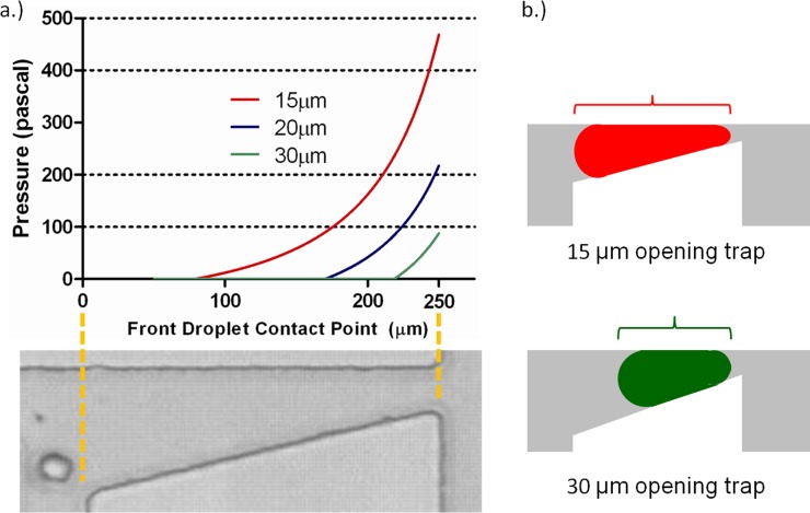
For a droplet of water with a spherical diameter of 50 μm in oleic acid (γ = 15.6 mN/m), the net Laplace pressure developed on the droplet as it enters the Laplace trap is shown in Figure 2 for different trap opening sizes. Trap opening sizes of 15 μm, 20 μm, and 30 μm were examined using MATLAB modeling. It can be seen from the plots that droplets develop the largest net Laplace pressure in the smallest trap simulated. As a droplet enters a trap, it elongates. In the smallest trap (15 μm opening), the droplet becomes elongated much more than the same size droplet in the largest trap (30 μm opening) would. Due to the linear relationship between the width of the trap and the position of the droplet in the trap, more elongation results in a larger distance between the front and back of the droplet, and a greater the difference between the radii. A greater distance between the radii correlates to a greater net Laplace pressure developed, as shown in Eq. 5. This concept is also illustrated in Figure 2b.
Figure 2.
(a) Results of MATLAB simulation, showing the effect of trap geometry on the development of net Laplace pressure on a 50 μm diameter droplet. A smaller trap size induces earlier constriction of the droplet and accordingly, earlier development of net Laplace pressure. For this simulation, devices with trap size values of 15, 20, and 30 μm at the terminal end of the trap were used. The photograph below the plot shows the corresponding physical position inside the Laplace trap indicated by the x-axis in the plot. (b) Droplets of equal volume elongate to a different extent in different-size traps. The relative elongation of a 50 μm diameter droplet in a 15 μm opening trap is much greater than the elongation of the same size droplet in a 30 μm opening trap. This differential elongation results in the different net Laplace pressure developed in identically sized droplets.
For the given system of a 50 μm diameter water droplet in oleic acid, any of the aforementioned trap sizes could be used to trap this droplet, provided that the hydrostatic pressure supplied by the continuous phase balances the Laplace pressure difference developed by differentially constricting the droplet. In subsequent simulations, the 20 μm trap size was used. Experimental observations revealed that this trap size was optimal for trapping 50 μm droplets, given the limitations of our pressure pumping equipment. In a 15 μm trap, the droplet is stopped in the trap well before the trap opening; this complicates subsequent release of the droplet from the trap. In the case of the 30 μm trap, a 50 μm droplet is slowed by the trap, but does not develop sufficient Laplace pressure to stop inside the trap. The 20 μm trap required a hydrostatic pressure that was within the optimal range of the pressure pumping system used. Using pumps with a different pressure range, or a wider pressure range, would facilitate the usage of other droplet trap sizes.
Effect of droplet size
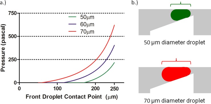
Selecting a trap with a 20 μm gap, the effect of droplet size on the net Laplace pressure developed can be obtained by varying the droplet volume in Eq. 4, while keeping the trap geometry and interfacial tension value constant (Figure 3). As expected, a larger droplet develops resistive pressure earlier than a smaller droplet due to the larger elongation achieved by larger droplets, which results in a greater difference in the Laplace pressure between the front and back interfaces of the droplet. If two droplets of different size constrict to the point at which they have the same radius of curvature at the front, the larger droplet will have a larger radius of curvature at the back thus resulting in a larger difference in the Laplace pressure between the front and back of the droplet. At the same location of approximately 175 μm a 50 μm-diameter droplet is still spherical while a 60 μm-diameter droplet experiences a net Laplace pressure of around 100 Pa and a 70 μm-diameter droplet experiences a net Laplace pressure of nearly double the magnitude. It should be noted that these simulations and observations apply only to droplets that are smaller than the trap area. For droplets that occupy a larger area than the trap, more complex behavior would be expected as the droplet begins to occlude flow to the bypass channel.
Figure 3.
(a) For a water droplet entering a Laplace trap with a terminal trap width of 20 μm, the net Laplace pressure developed depends on the size of the droplet. For the same size trap, larger droplets develop more Laplace pressure since the length dimension becomes greater for these droplets than for smaller droplets. (b) In a 20 μm opening trap, droplets of smaller size elongate to smaller extents than droplets of greater size. The extent of elongation direclty correlates to the distance between the front and back radii of the droplet, and results in the development of net Laplace pressure on the droplet.
Effect of system chemistry
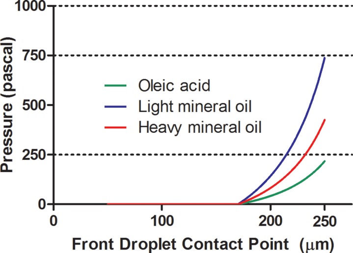
As a variety of reagent combinations are employed for different droplet-based systems, the effect of the interfacial tension on the stopping location of the droplet was investigated by changing γ in Eq. 3. Figure 4 shows a plot of calculated net Laplace pressure for a system with the trap opening of 20 μm, and a 50 μm diameter aqueous droplet in three different continuous phases: light mineral oil (LMO), heavy mineral oil, and oleic acid. The interfacial tension values between water and light mineral oil, heavy mineral oil, and oleic acid are 52.93 mN/m (Ref. 12), 30.5 mN/m (Ref. 13), and 15.6 mN/m (Ref. 14), respectively. As expected, for systems with a higher interfacial tension – such as water in light mineral oil, more Laplace pressure is developed as the droplet moves into the trap, and thus the droplet stops earlier in the trap than it would for systems of lower interfacial tension – such as oleic acid. Since the addition of surfactant to the system generally lowers the interfacial tension between the phases, it would also decrease the net Laplace pressure developed. As a result, the addition of surfactants may reduce the Laplace pressure to a large enough extent as to completely prevent the droplet from stopping inside the Laplace trap. For systems where surfactants are required, other variables, such as the trap geometry and droplet size can be altered in order to achieve complete stoppage of the droplet at the desired location inside the trap.
Figure 4.
The effect of different chemistries on the development of Laplace pressure in a 50 μm diameter droplet entering a 20 μm trap. Following Eq. 3, the developed Laplace pressure is greater for systems with a higher interfacial tension value.
COMPUTATIONAL FLUID DYNAMICS SIMULATION OF DROPLET TRAPPING
Combining the results of MATLAB simulations to explore the variable space for successful operation of the trap with experimental observations, a system of a 50 μm water droplet in oil, using in a 20 μm trap was chosen. Successful trapping of this size droplet was consistently observed using the hydrostatic pressure ranges available with the pressure pumping system used. Given a greater range of supplied pressures, the trap could be configured to trap droplets of different sizes and different compositions, using the results of the MATLAB simulations for guidance. To more fully appreciate the effect of varying the force induced on a droplet due to hydrostatic pressure, we employed a computational fluid dynamics-based simulation. The package CFD-ACE was used to simulate the movement of a droplet into the Laplace trap in 3 dimensions when various values of hydrostatic pressure were applied. By simulating the droplet behavior in 3-D, factors that were not taken into account in the MATLAB simulations such as the precise shape of the deformed droplet and droplet-wall interactions would be accounted for. The volume of fluid (VOF) module was used to simulate two-phase flow, with a water droplet inside of a microchannel filled with oleic acid. Surface tension effects were enabled, and the flow was solved using a 2nd order piecewise linear interface construction (PLIC) scheme. Due to a lubrication layer of oleic acid around the droplet at all times,15 the water droplet was assumed to have no direct contact with the channel walls. Thus, the contact angle for the water on the channel walls was set to 180°, completely nonwetting.
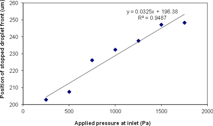
Using a simplified geometry of the Laplace trap to reduce computation time, a constant pressure source of between 250 and 2000 Pa was applied 200 μm upstream of the entrance to the trap region (results shown in the supplementary information). The position of the droplet was tracked over time during the simulation, and the stopping position of the droplet was recorded for various applied pressures, as shown in Figure 5. For a low hydrostatic pressure of 250 Pa, the droplet moves comparatively slowly into the trap and the front of the droplet stops at a position of 203 μm into the trap. As the applied hydrostatic pressure increases, the droplet moves more swiftly into the trap and the stopping position of the droplet is farther along in the trap. At an applied hydrostatic pressure of 2000 Pa, the droplet does not stop in the trap at all, due to an insufficient difference in the front and back Laplace pressures developed on the droplet to counteract the applied hydrostatic pressure. Using the information obtained from the simulation and the Hagen-Poiseuille equation for hydraulic resistance in square channels, it is possible to calculate the pressure needed at the inlet of the device to trap the droplet, if the length of the channel from the inlet to the Laplace trap is determined.
Figure 5.
Results of a CFD-ACE simulation for a 50 μm diameter droplet moving into the Laplace trap. For a higher applied hydrostatic pressure, the droplet stops farther into the trap. This figure demonstrates that the stopping position of a droplet in the trap may be controlled by regulating the hydrostatic pressure of the continuous phase. At an applied pressure of 2000 Pa, the hydrostatic pressure on the droplet overcame the Laplace pressure developed, and the droplet was not stopped in the trap.
RESULTS AND DISCUSSION
Droplet trapping and on-demand release
On-demand release of trapped droplets can be achieved by disturbing the balance between the applied hydrostatic pressure (Eq. 2) and the Laplace pressure (Eq. 1) experienced by the droplet. Here, we demonstrate that controlled, on-demand droplet release can be achieved by increasing the local hydrostatic pressure behind a droplet, or by decreasing the net Laplace pressure on the droplet. The ability to controllably release the droplet using either method demonstrates utility of the trap and validates the mathematical modeling the trap design was based upon.
Mechanical release of droplets
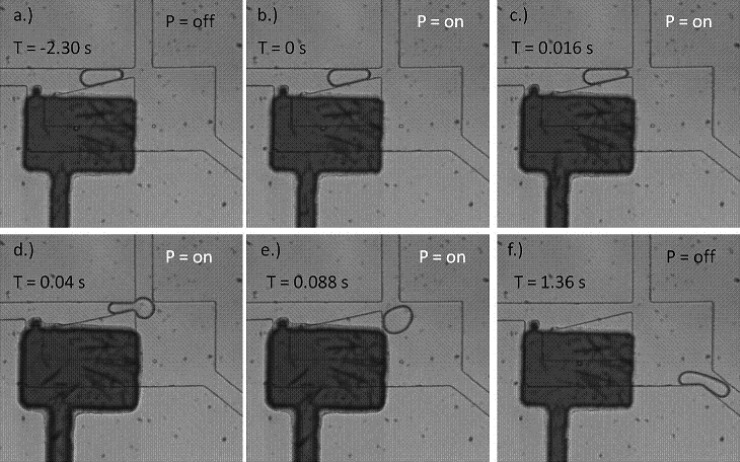
Under normal device operation, the flow of continuous phase fluid from the left inlet of the device divides to occupy the upper branch (the Laplace trap) and lower (bypass) branch (Figure 1a). When a droplet occupies the upper branch and is trapped, the full volumetric flow of the continuous phase moves to the bypass channel. By creating a structure that can occlude the bypass channel on-demand, it is possible to momentarily increase the hydrostatic pressure applied to the droplet from the left, and disturb the balance of Laplace pressure and hydrostatic pressure. An increase in hydrostatic pressure allows the trapped droplet to overcome the Laplace pressure holding it in the trap, and the droplet is pushed through the narrowest part of the trap and released.
To temporarily restrict flow in the bypass channel and thus trigger droplet release from the trap, a pneumatically actuated valve structure16 was designed and placed over the bypass channel of the Laplace trap (Figure 6). A thin PDMS membrane acts as the actuation component of the design. In Figure 6 this is represented by the dark fluidic channel. The channel is filled with aqueous dye solution to assist in visualizing the chamber. When the thin membrane is pressurized with air, it deflects into the fluidic channel below, partially occluding the flow and increasing the resistance across the bypass. This abrupt occlusion of flow in the bypass channel produces a small backflow of fluid from the bypass channel, which provides a temporary increase in the hydrostatic pressure in the upper channel. As a result, the hydrostatic pressure overcomes the Laplace pressure holding the droplet in the trap, and the droplet is released (Figure 6). Panel (a) shows the droplet stably held in the Laplace trap. With no external force disturbing the balance the droplet will be trapped indefinitely. In panel (b) the membrane has just been actuated and the droplet is at the same location as in (a). Panel (c) shows that shortly after the membrane actuation, the droplet has moved closer to the opening of the trap. In panel (d), approximately half of the droplet has flowed past the trap opening. The last two panels shows the droplet completely leaving the trap and exiting through the outlet channel. In this manner, droplets can be released rapidly and with precise control.
Figure 6.
Time-series of images showing the release of a droplet from the Laplace trap upon actuation of a membrane valve at 20 psi. The flag-shaped structure comprises a membrane valve which can be pressurized. The membrane deflects downward, into the fluidic channel, and greatly increases the fluidic resistance through the bypass path. The resulting increase in hydrostatic pressure behind the droplet pushes it out of the Laplace trap.
With an array of Laplace trap structures, each trapping a single droplet, on-demand control of droplet release from each trap could be realized by fabricating a valve structure for each trap that could be actuated independently.
Interfacial tension-mediated release of droplets
Another way to release a droplet from the Laplace trap is to lower the net Laplace pressure on the droplet, allowing the hydrostatic pressure to overcome the net Laplace pressure. One way to accomplish this is to change the interfacial tension on one side of the droplet. From Eq. 6,
| (6) |
It can be readily observed from this equation that a decrease in γfront relative to γback will result in a lower net Laplace pressure. Increasing surfactant concentration will decrease the interfacial tension of an oil-water system.12 For a surfactant-free system of mineral oil and water, γfront = γback = 52.93 mN/m. Using values obtained from the MATLAB calculations for the front and back radii of a 50 μm droplet moving into a 20 μm trap, the net Laplace pressure on this droplet was calculated to be 683 Pa. If surfactant is added to the continuous phase that flows in front of the droplet, the interfacial tension decreases. To produce a zero net Laplace pressure on the droplet at this position, γfront must be lowered to a value of 44 mN/m. This can be achieved by the addition of 0.0025% (v/v) Span-80 surfactant to the mineral oil continuous phase, as specified in Opawale and Burgess.12 Therefore, the addition of even a low concentration of surfactant decreases or eliminates the Laplace pressure on a droplet that retains the droplet in the trap. Once the Laplace pressure has been changed in this manner, the hydrostatic pressure supplied by the continuous phase produces enough force to push the droplet out of the trap.
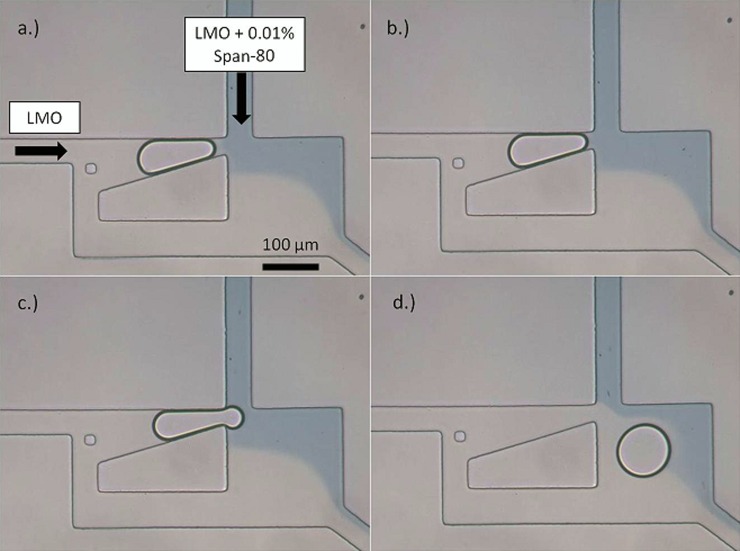
This is accomplished experimentally by designing a Laplace trap inlet with valves to switch the continuous phase. At first, 100% light mineral oil is pumped into the device from the top and side inlets. After a droplet is trapped, surfactant is gradually added to the continuous phase in the top inlet by opening a valve holding a solution of light mineral oil with 0.01% (v/v) Span-80, a surfactant. After the phase was switched, the concentration of surfactant from this inlet steadily increased to a maximum value, which was observed by means of adding oil blue dye. As the concentration of surfactant increases, the net Laplace pressure on the trapped droplet decreases until is it overcome by the hydrostatic pressure in the channel. When this occurs, the droplet is released from the trap as shown by the image sequence in Figure 7.
Figure 7.
100% light mineral oil is pumped into the Laplace trap from the left side, while the top inlet is connected to valves allowing for switching of the continuous phase from 100% mineral oil to 0.01% (v/v) Span-80 in mineral oil (indicated by oil blue dye). (a) A single droplet is trapped soon after switching the phases, when the phase has not completely switched and the surfactant concentration is low. (b) As the concentration of surfactant increases, the droplet moves forward in the trap, and comes fully into contact with the surfactant-added phase. (c) and (d) The droplet is released, due to a decrease in the net Laplace pressure.
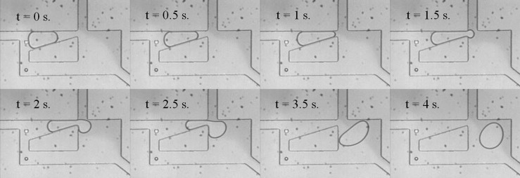
In another experiment, the continuous phase from the top inlet was switched from a phase containing light mineral oil, to a phase containing 5% v/v Span-80 in light mineral oil. When the surfactant concentration had reached its maximum value, droplet trapping was no longer observed. Instead, droplets of various sizes slow in the trap but do not stop, as shown in Figure 8.
Figure 8.
When the surfactant concentration has reached a maximum (5%), droplets are no longer trapped, but only slowed in the trap region.
Due to the technique used to switch continuous phase flow from mineral oil to a phase containing mineral oil and the surfactant (an off-chip 2-way valve), the change of phase was rather slow, requiring several minutes. Accordingly, releasing a droplet from the trap in this manner required several minutes. While this speed would not be practical for most microfluidic application, the technique is presented to illustrate how alteration of the interfacial tension on a select portion of the droplet sufficiently disturbs the Laplace pressure to release a droplet from the trap.
Another method involving these principles, but using a different approach, may allow for faster release of droplets (approaching the speed of the mechanical release technique discussed in Sec. 6B). Selective surface tension disruption on one side of a trapped droplet could, for instance, be accomplished by adding electrodes on the chip to rapidly heat the upstream side of the droplet, decreasing the interfacial tension on the heated side, and allowing for quick release of the droplet from the trap.
Droplet fusion and selection using the Laplace trap
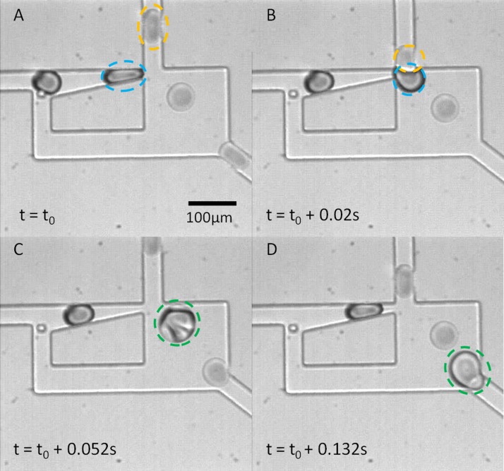
In addition to the trap-and-release abilities demonstrated for the Laplace trap, this geometry has features that confer additional functionality to the device. One of these is the ability to fuse droplets from different inlets of the device. Once a droplet is trapped, the droplet remains in the trap indefinitely. Placement of the trapped droplet in close proximity to another droplet stream allows the trapped droplet to fuse with a droplet from another stream. This arrangement is illustrated in Figure 9. A single droplet is trapped (indicated in blue) until a droplet incoming from a perpendicular stream (yellow) passes the trapped droplet. The presence of the yellow droplet at the exit momentarily reduces the hydrostatic force pushing back on the trapped droplet causing it to move forward slightly, toward the fusion junction. Once the two droplets begin to merge, the front interface of the combined droplet increases in size, and this increase in Ry,f allows the rest of the droplet to pass easily through the trap neck, completing the fusion. After fusion, the contents of the fused droplets mix and exit the device, allowing a new trapping and fusion cycle to begin. This configuration allows for up to 100% fusion of the droplets from the left stream (indicated in blue in Figure 9), while using an excess of yellow droplets. The device could be used to fuse droplets with different contents, when one of the droplets contains a valuable or expensive reagent.
Figure 9.
The Laplace trap provides a passive means for the fusion of two separate droplet trains. Using such a device, two droplets need not be synchronized in time, since the trap allows for the space synchronization that facilitates matching and subsequent fusion of the trapped droplet with a second droplet. In (A), a water droplet (blue) is trapped, while a droplet of 50:50 water: glycerol (v/v) approaches from the top inlet. In (B), co-localization of the two droplets, facilitated by the Laplace trap, enables fusion of the droplets to occur. (C) and (D) show mixing within the fused droplet and the beginning of another trapping event.
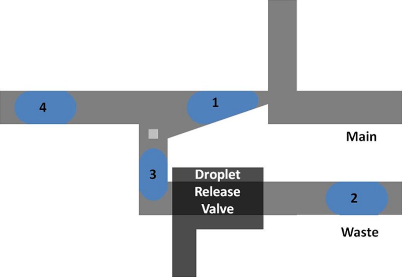
An additional functionality of this trap is to allow for selection of the first droplet from a train of droplets. The first droplet to pass into the device becomes trapped, while the bypass channel (Figure 1a) allows subsequent droplets to travel through it and to the outlet of the device. A slight modification of the design shown in Figure 1 would allow trapped droplets to exit to a different outlet than subsequent droplets, as shown in Figure 10 below. In this design, the first droplet of a droplet train moves into the Laplace trap. Subsequent droplets are carried through the bypass channel and to the waste outlet. Once these droplets have been discarded, a droplet release valve (similar to the one shown in Figure 6) could be employed to release the trapped droplet “1”, and begin a new trapping cycle.
Figure 10.
By modifying the original design to include separate outlets for the trap and bypass channels, the first droplet of a train could be directed toward a different outlet than all subsequent droplets. The addition of a droplet release valve, such as the one shown in Figure 6, would allow for release of the trapped droplet and initiation of the next trapping cycle.
This type of functionality might be particularly useful for the technique of microfractionation, in which the concentration of a compound of interest in a train of droplets varies. In this technique, various compounds within a plug of fluid are separated from one another by one of several techniques which may include capillary electrophoresis, chromatography, or the hydrodynamic repellant effect.17, 18, 19 When the plug is sheared into several droplets, each droplet in the train contains different concentrations of the compounds initially in the plug. By designing a separation scheme to isolate protein or DNA toward the front end of the plug, it would thus be possible to concentrate this component in the first droplet of the train. In this case, the Laplace trap design shown in Figure 10 could be used to select the first droplet containing the concentrated or purified DNA or protein from the train, while discarding the other droplets containing compounds of lesser interest.
In addition, this geometry could also be used to allow for fusion of trapped droplet “1” (Figure 10) to a droplet incoming from the top inlet, allowing the addition of reagents to the trapped droplet, and releasing the droplet for downstream processing. Considering the microfractionation example presented above, the second droplet from the top inlet could contain reagents necessary to execute on-chip polymerase chain reaction when combined with the droplet of DNA in the Laplace trap. This configuration would ensure that the contents of the “Main” microfluidic channel contain only droplets that have fused, since the unfused blue droplets are carried to a separate outlet. This eliminates the need for a downstream sorting process for unfused droplets.
Multiplexing potential and throughput of the Laplace trap
The Laplace trap provides several unique benefits over previously published droplet trap devices, including the ability to release a single trapped droplet on-demand, the ability to continually trap and release droplets from a single trap, and the ability to use the trap to ensure 100% fusion of droplets entering the trap from the left inlet. In Sec. 6B, the release of a trapped droplet via actuation of a mechanical valve was demonstrated as a potential technique to process droplets continually in the device. Upon actuation of the valve, the droplet was released from the trap in 88 ms. Further optimization of the actuation pressure in the membrane valve, as well as the speed of continuous phase flow in the device, could potentially increase the throughput of this technique further, to allow for processing of more than one droplet per second. Similarly, for the droplet fusion application in Sec. 6D, fusion events as fast as 3-5 droplets per second were observed, demonstrating good throughput for a passive fusion device. To further increase the overall throughput of the device, several Laplace traps could be placed in series on the same device. Release of a single droplet from an array of droplets trapped in this manner could be accomplished by fabricating an independent actuation valve for each trap, similar to the design shown in Figure 6. Using this technique could potentially allow for pairing and fusion of trapped droplets with droplets of differing contents that enter from the top inlet, as shown in Figure 9. In a serial array of Laplace traps, each top inlet could contain droplets with a different substance, allowing combinatorial pairing of droplets from different inlets using the Laplace trap. This configuration could allow for an unprecedented degree of combinatorial pairing of droplets with different contents, limited only by the amount of instrumentation available for generating droplets and actuating valves in the device.
CONCLUSIONS
A novel microfluidic design for the trapping, controlled release and selection of droplets has been characterized through both modeling and experimentation. Trapping of a droplet is achieved when a balance between the hydrostatic pressure, supplied by the continuous phase, and the net Laplace pressure developed on the droplet as a result of its constriction in the channel is reached. The simulation results provided demonstrate the flexibility of the trap for use with different droplet sizes and system chemistries and advise the selection of appropriate parameters for trapping in a wide variety of applications. This device provides a unique benefit over published droplet traps, as it allows for indefinite observation of a droplet in the trap, with the ability to reliably release the droplet from the trap on-demand. Such capabilities are of great value to many droplet-based applications, such as kinetics studies of chemical reactions in droplets, and single cell analysis.
In addition, the component offers several functionalities not yet demonstrated in a device for controlled droplet trapping and release, including droplet selection and synchronization. The droplet could be predictably and reliably released from the trap using a variety of methods to either increase the hydrostatic pressure behind the droplet, or lower the net Laplace pressure on the droplet. The unique design of the geometry presented here allows for extraction of the first droplet from a train, as well as providing a passive means of droplet synchronization. The work presented here provides a means by which to accomplish many useful droplet unit operations. The Laplace trap could be incorporated as an integral component of microfluidic droplet processors, capable of performing droplet trapping, incubation, synchronization, controlled release, and fusion.
ACKNOWLEDGMENTS
The authors would like to thank Andrew Hatch for his valuable suggestions and Maulik Patel for his assistance with the CFD-ACE simulations.
References
- Brouzes E., Medkova M., Savenelli N., Marran D., Twardowski M., Hutchison J. B., Rothberg J. M., Link D. R., Perrimon N., and Samuels M. L., Proc. Natl. Acad. Sci. 106, 14195 (2009). 10.1073/pnas.0903542106 [DOI] [PMC free article] [PubMed] [Google Scholar]
- Cordero M., Burnham D., Baroud C., and McGloin D., Appl. Phys. Lett. 93, 034107 (2008). 10.1063/1.2952374 [DOI] [Google Scholar]
- Reiner J., Crawford A., Kishore R., Goldner L., Helmerson K., and Gilson M., Appl. Phys. Lett. 89, 013904 (2006). 10.1063/1.2219977 [DOI] [Google Scholar]
- Basu A. and Gianchandani Y., J. Micromech. Microeng. 18, 115031 (2008). 10.1088/0960-1317/18/11/115031 [DOI] [Google Scholar]
- Zagnoni M. and Cooper J., Lab Chip 9, 2652 (2009). 10.1039/b906298j [DOI] [PubMed] [Google Scholar]
- Hunt T., Issadore D., and Westervelt R., Lab Chip 8, 81 (2008). 10.1039/b710928h [DOI] [PubMed] [Google Scholar]
- Wang W., Yang C., and Li C., Lab Chip 9, 1504 (2009). 10.1039/b903468d [DOI] [PubMed] [Google Scholar]
- Schmitz C., Rowat A., Köster S., and Weitz D., Lab Chip 9, 44 (2009). 10.1039/b809670h [DOI] [PubMed] [Google Scholar]
- Boukellal H., Selimovic S., Jia Y., Cristobal G., and Fraden S., Lab Chip 9, 331 (2008). 10.1039/b808579j [DOI] [PubMed] [Google Scholar]
- See supplementary material at http://dx.doi.org/10.1063/1.3687400 for a more rigorous description of the geometrical calculations as well as a description of the limitations of the MATLAB and CFD-ACE simulations.
- Stroock A. D. and Whitesides G. M., Electrophoresis 23, 3461 (2002). [DOI] [PubMed] [Google Scholar]
- Opawale F. O. and Burgess D. J., J. Colloid Interface Sci. 197, 142 (1998). 10.1006/jcis.1997.5222 [DOI] [PubMed] [Google Scholar]
- Shively M. L., Pharm. Res. 10, 1153 (1993). 10.1023/A:1018912100826 [DOI] [PubMed] [Google Scholar]
- Kamogawa K., Okudaira G., Matsumoto M., Sakai T., Sakai H., and Abe M., Langmuir 20, 2043 (2004). 10.1021/la030160z [DOI] [PubMed] [Google Scholar]
- Liau A., Karnik R., Majumdar A., and Cate J., Anal. Chem. 77, 7618 (2005). 10.1021/ac050827h [DOI] [PubMed] [Google Scholar]
- Unger M., Chou H., Thorsen T., Scherer A., and Quake S., Science 288, 113 (2000). 10.1126/science.288.5463.113 [DOI] [PubMed] [Google Scholar]
- Trivedi V., Doshi A., Kurup G., Ereifej E., Vandevord P., and Basu A. S., Lab Chip 10, 2433 (2010). 10.1039/c004768f [DOI] [PubMed] [Google Scholar]
- Sehgal P., Doshi A., and Basu A. S., Microfractionation of CE-separated compounds into Droplets, In microTAS, Seattle, WA, 2011.
- Fang W. F., Ting S. C., Hsu C. W., Chen Y. T., and Yang J. T., Lab Chip 12, 923 (2012). 10.1039/C2LC20917A [DOI] [PubMed] [Google Scholar]


