Abstract
We propose a simple method for forming massive and uniform three-dimensional (3-D) cell spheroids in a multi-level structured microfluidic device by gravitational force. The concept of orienting the device vertically has allowed spheroid formation, long-term perfusion, and retrieval of the cultured spheroids by user-friendly standard pipetting. We have successfully formed, perfused, and retrieved uniform, size-controllable, well-conditioned spheroids of human embryonic kidney 293 cells (HEK 293) in the gravity-oriented microfluidic device. We expect the proposed method will be a useful tool to study in-vitro 3-D cell models for the proliferation, differentiation, and metabolism of embryoid bodies or tumours.
INTRODUCTION
Formation of cell spheroids is one of the essential tools for studying the behaviours of a 3-D cellular model. The 3-D cellular model should be used to mimic the in-vivo environments better (e.g., diffusion and transport conditions of drugs, nutrients, and oxygen).1 Further, the cellular spheroid size of the embryoid bodies (EBs) is a critical cue of its differentiation, resulting in different consequences.2, 3 Cell spheroids are also more reliable material than two-dimensional (2-D) cellular models for drug screening in clinical research.4, 5 For example, in tissue engineering, experimental results in 2-D cellular models do not match to those in clinical trials, because the chemical and physical behaviors in tissues or organs are based on the 3-D cellular models. The conventional method for the formation of spheroids includes a hanging drop method,6, 7 a rotary shaker,8 and a stirring vessel.9 However, these techniques are still not suitable for the precise control of spheroid size and microenvironments.
Microfluidics and microtechnology have enabled the formation of a uniform spheroid size. A very simple method of using non-adhesive polyethylene glycol (PEG) microwell arrays has been employed to adjust the EB size by geometrical confinement of the microwells.10 A multi-layer microfluidic device with a porous membrane was employed to achieve both the spheroid formation and in-situ culture.11 A microfluidic array platform containing concave microwells and flat cell culture chambers for both EB formation and its culture was also introduced.12 Previously, we reported a microfluidic network-based 3-D cell culture device consisting of cell-docking chambers with multi-depth structures. However, the device was limited in use by a syringe pump-based operation procedure and large device size.13
The issues and essential functions often encountered in using such 3-D cell culture microsystems include a user-friendly method, easy fabrication, size regulation, in-situ and long-term culture, and retrieval of cell spheroids. In this paper, we propose a simple method to deal with the above issues by utilizing the concept of orienting the device vertically, permitting standard manual pipetting and designing an electric circuit analogy-based microfluidic network:
-
(1)
Our approach is simple because all procedures are based on user-friendly standard pipetting.
-
(2)
3-D structures can be easily fabricated by conventional 2-D soft-lithography process. Furthermore, we can scale up the number of microchambers in a parallel configuration.
-
(3)
By controlling the initial concentrations of cells, we can precisely regulate the size of the cell spheroids within geometrical ranges.
-
(4)
The methodology provides in-situ and long-term culture of cell spheroids by designing appropriate trap geometry and microfluidic network-based perfusion configuration.
-
(5)
Lastly, we can retrieve cell spheroids from the trap microchambers simply by reverse flow for further biological experimentation.
WORKING PRINCIPLE
The device consists of three layers for (1) reservoirs, (2) multi-level structures (e.g., 50 thick rounded trap microchambers, thick main channels, thin perfusion channels, and inlet/outlet ports), and (3) a bottom substrate (Fig. 1a). The channel network was configured based on the analogy between electric and hydraulic circuit.14 In this design, a predominant design rule is that the hydraulic resistance of the perfusion channels is much higher than that of the others: RD (the perfusion channel) ≫RA (the upper main channel, e.g., RD ≈ 1000 × RA), RB (the neck), RC (the trap chamber), RE (the lower main channel) (Fig. 1b). Thus, this design concept does not require the complex calculation and geometrical adjustment (e.g., channel length) compared to our previous work15 because RD is dominated when the channel networks are analysed. In addition, when the inlet ports and outlet ports are opened, the high resistance of RD plays a role for a passive valve. To make the high resistance of RD, it was adjusted by the shallow channel with 5 μm thick, which could also trap the cells in the chamber without loss of the cells when the device is turned vertically because the cell size (≈10 μm) is bigger than the channel height (5 μm). Next, neck structures were designed to be 200 μm wide. The maximum size of spheroids formed in this device was limited to the height of chamber (300 μm). When the cells are aggregated, the neck structures (150 μm) prevent an occasional release of the spheroids into the main channel. The working principle for the formation and the retrieval of spheroids of EBs is illustrated with equivalent electric circuits (Fig. 1c).
Figure 1.
Schematic of the proposed gravity-oriented microfluidic device for cell spheroid formation. (a) Design parameter of the proposed device configuring multi-level structures. (b) Equivalent purely resistive electrical circuit. (c) Working principle for the formation and retrieval of the cell spheroids: 1. cell loading by standard pipetting; 2. cell down by orienting the device vertically; 3. spheroid formation; 4. gravity-driven perfusion; and 5. spheroid retrieval by reverse flow. (d) Side and top views of each procedure (enhanced online)
First, the cells are loaded into port 1 by standard pipetting (Fig. 1(d1-1)). The loaded cells flow from port 1 to port 2 and fill the upper main channel. The relatively high hydraulic resistance of the shallow perfusion channels prevents the inflow through the chambers (passive valve). Once the main channel is filled with the cells, ports 1 and 2 are closed by size-customized tip valves (Fig. 1(d1-2)). Then, the device is turned vertically for an incubation time of 10 min and most of the cells are evenly trapped to each chamber by gravity (Fig. 1(d2-1)).13 In the next step, the remaining cells in the main channel are flushed out with a fresh medium, whereas the precipitated cells in the chambers are not nearly affected by the flow due to RD ≫ RA, RB, RC, RE (Fig. 1(d2-2)). Within a day, the cell spheroids are well formed in the chambers (Fig. 1(d3)). When the cells are aggregated, the neck structures prevent an occasional release of the spheroids into the main channel. In this system, gravity-driven perfusion of a medium, to feed nutrients and remove cellular waste, is also applied with the pressure head difference between ports 1 and 2 and ports 3 and 4 (Fig. 1(d4)).16, 17, 18 Due to RD ≫ RA, RB, RC, RE, the input medium is evenly perfused.15, 19 Lastly, if retrieval of the cell spheroids is required, they can be extracted from the trap chambers by applying reverse flow from port 4 to port 1 (Fig. 1(d5)).
MATERIAL AND METHOD
Microfabrication
The microfluidic device was fabricated by the multi-level SU-8 fabrication method and polydimethylsiloxane (PDMS) replica moulding.20 For the first level of 5 μm film, SU-8 2005 photoresist (Microchem, Newton, MA, USA) was coated on a silicon wafer, selectively exposed to define the shallow perfusion channels of 5 μm, and post-baked (not developed yet). For the second level of 300 μm film, SU-8 2050 photoresist (Microchem, Newton, MA, USA) was coated twice with a thickness of 150 μm above the first film (5 μm film) and exposed to define the thick channels (main channels) and chambers. All SU-8 layers were then simultaneously developed. PDMS (Sylgard 184, Dow Corning, Midland, MI, USA) was poured onto the patterned mould (for the middle layer) and two non-patterned plat substrates (for the top and bottom layers). After curing, the PDMS replicas were peeled off from the silicon substrates. Inlet and outlet holes were punched through the patterned PDMS slab. Following air plasma treatment, the middle PDMS slab was bonded to the bottom PDMS slab. In the same manner, the top PDMS slab with four reservoirs of 8 mm diameter and 10 mm height was bonded to the preformed middle/bottom slab. To make the channel walls resistant to cell adhesion, 5% w/v bovine serum albumin (BSA, Sigma) was introduced into the channels and incubated overnight.
Cell preparation
HEK 293 cells (human embryonic kidney 293 cells) were maintained in Dulbecco’s modified eagle’s medium (DMEM) supplemented with 10% foetal bovine serum (Invitrogen Cat. No. 16140071) and 1% penicillin-streptomycin (Invitrogen, Cat. No. 15070-063) at 37°C and 5% CO2. To facilitate the spheroid formation of HEK 293, 3% (w/v) polyvinylalcohol (PVA) was added to the cell suspension.21 HEK 293 cells were transfected with enhanced green fluorescent protein (EGFP) by lipofectamine 2000 (Invitrogen Cat. No. 11668019) according to the manufacturer’s protocol. The EGFP was used to assess cell viability. An inverted microscope (Olympus IX81), using a mercury lamp source, was used to observe the cell spheroids.
RESULTS AND DISCUSSIONS
Cell loading and cell down
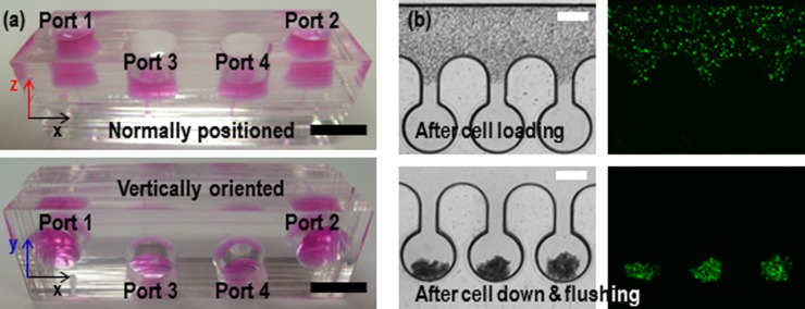
First, we investigated the even distribution of the cell suspension across the trap chambers and performed cell loading and cell down using the fabricated device (Fig. 2a). HEK 293 cell suspension (20 μl) was loaded into port 1 using standard pipetting (top in Fig. 2(b)). The shallow perfusion channels ensured no noticeable inflow of the cell suspension into the chambers, resulting in uniform cell distribution across the main channel. In this methodology, the most important property of fluid is a viscosity. It will influence on the cell down as well as perfusion process, which will limit the use of methodology. However, in the level of viscosity of the conventional mediums, the cell down and perfusion process will work well without problem because the viscosity of our perfusion medium (PVA added) is similar to or higher than others. Then, the device was turned vertically and incubated for 10 min at the closed state of ports 1 and 2 by plugging them with tip valves. The cells settled down evenly into each chamber by gravity, and the cells remaining in the main channel were flushed out to port 2 by adding a culture medium in the reservoir of port 1 (bottom in Fig. 2(b)). In our design, round-shaped side wells prevented clogging of the cells at the wall surface. Moreover, the rounded surface enhanced clustering of the sediment cells at one point in the chambers (i.e., bottom of the chamber).
Figure 2.
(a) Photographs of the microfluidic device when the device is normally positioned (top) and vertically oriented (bottom). (b) The captured images after loading HEK 293 cells in the state of the normal position (top) and after settling down into the trap chambers by gravity in the state of vertical standing (bottom). The green colour represents cell viability. The scale bars are 1 cm and 300 μm for (a) and (b), respectively.
Size regulation of cell spheroids
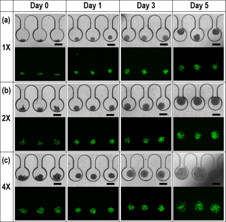
Next, we studied spheroid size regulation of the HEK 293 EBs with different initial concentrations: 1 × 10⁶/ml (Fig. 3a), 2 × 10⁶/ml (Fig. 3(b)), and 4 × 10⁶/ml (Fig. 3(c)). After 0 day (i.e., 10 min), 1, 3, and 5 days, the morphologies of the cell spheroids and the corresponding fluorescence images were captured for assessment of long-term perfusion and spheroid viability. Usually, the conventional hanging drop method needs an aggregation time of more than one day (>24 h) with a wide range in the size variation of spheroids.6, 7 Our method enabled uniform spheroid formation with a time of less than one day (<24 h). The hanging drop method generally used in laboratories is limited to manual methods. When the cell suspensions are hanging from cell culture dish, the radius of curvature is not uniform, resulting in several spheroids in the single hanging drop. Thus, they need more time to be aggregated each other. However, micro-confined structures can gather the cells into a single spot at once, reducing the time to be single and uniform spheroids. Then, the spheroids were long-term cultured by the gravity-driven perfusion of a medium for 5 days. The dimension of microchambers was 500 μm and 300 μm in diameter and height, respectively. If the size of spheroids is exceed above the height (300 μm), the spheroids will be deformed to cylindroids. In this study, the reason the spheroids were grown above the limitation was to demonstrate our perfusion system is robust for the cell culture. If the spheroids are retrieved before the limitation, they will maintain spherical morphology. The captured EGFP images confirm excellent viability of the perfused spheroids.22, 23
Figure 3.
Morphologies of HEK 293 cell spheroids after 0 day (i.e., 10 min), 1, 3, and 5 days and the corresponding fluorescence images for cell viability with different cell concentrations: (a) 1 × 10⁶/mL, (b) 2 × 10⁶/mL, and (c) 4 × 10⁶/mL. The scale bar is 300 μm.
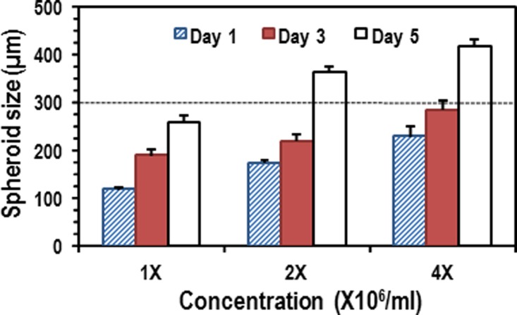
Figure 4 shows the size distribution of the spheroids in the given conditions. The cross-validation (CV) errors of the sizes of the spheroids in 1 day were 5.5%, 7.2%, and 8.9% for 1×, 2×, and 4×, respectively. As the EBs were growing in the chambers, their size was comparable to the chamber dimensions (300 μm in height and 500 μm in diameter). The increasing rate of the spheroid size for 3 days was 19.9%, 10.1%, and 9.2% per day for 1×, 2×, and 4×, respectively. The tendency of lower increasing rate in the large spheroids can be attributed to limited chamber volume and mechanical stress. Once the spheroids (for 2× and 4×) grew up to geometrical limitation of channel height (300 μm), they were laterally extended, which showed higher increasing rates than those for 3 days. Thin terrace structures surrounding the microchambers could prevent the spheroids from obstructing the narrow perfusion channel, thereby allowing maintenance of smooth flow via the terrace structure even though the spheroid sizes are greater than the chamber height.24 The spherical size was well regulated by the initial cell concentrations and long-term perfusion, even though the chamber dimensions need to be further optimized to grow EBs larger than 300 μm.
Figure 4.
The results of spheroid growth (diameter) for a 5-day culture with different initial cell concentrations. The average increasing rates are 19.2%, 10.1%, and 9.2% for 1×, 2×, and 4×, respectively.
Retrieval of cell spheroids
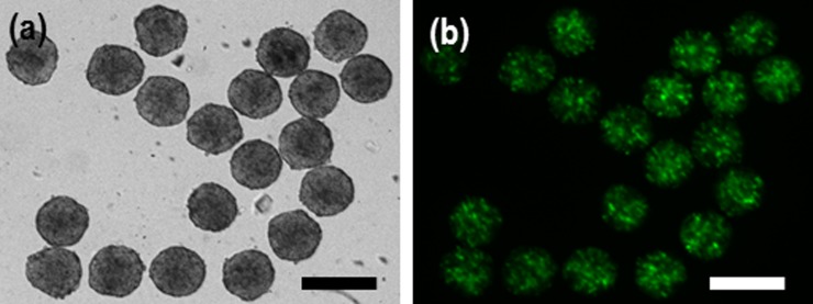
Spheroid retrieval with high efficiency is a desirable property of 3-D cell culture systems. Successful retrieval allows for further experimentation, such as the molecular biology analysis of EBs or encapsulation of spheroids within biomaterials for developing functional tissue constructs. We performed the retrieval process by means of similar standard pipetting. The backflow from port 4 to port 1 was initiated by closing ports 2 and 3 and injecting a medium from the port 3. The 3-day cultured spheroids with 2× concentration (∼220 μm) were successfully extracted using the back flow procedure (Fig. 5). Spheroids smaller than ∼300 μm were easily retrieved even though the neck size of the chamber was 150 μm. This was due to the elasticity of spheroids facilitating easy release from the trap chambers without difficulty. The design strategy through gravity-oriented methodology, standard manual pipetting, electric circuit analogy, and rounded channel geometry allowed straightforward device handling for cell loading, spheroid formation, long-term perfusion, and the retrieval of the cell spheroids.
Figure 5.
(a) Retrieval results of cell spheroids after culture for 3 days by backflow with standard pipette process as shown in Figs. 1(d5) and 1(b) viability of the spheroids extracted from the microchambers. The flexibility of the cell spheroids makes extraction from the microchambers easy. The scale bar is 300 µm.
CONCLUSION
We demonstrated a simple and effective method of forming cell spheroids in a gravity-oriented multi-level structured microfluidic device. With HEK 293 cell, uniform and well-conditioned EBs were formed and cultured for 5 days using the gravity-driven perfusion device. The size of spheroids was well regulated by adjusting the initial cell concentrations and long-term perfusion. By applying reverse flow for the retrieval of the spheroids, we could easily extract them from the microchambers without damage, showing scope for further standard biological experimentation. Thus, we expect the proposed method will give valuable insight into the study of 3-D cell culture models without a significant level of device handling skills.
ACKNOWLEDGMENTS
We would like to thank Professor Malcolm M. Slaughter, Department of Physiology and Biophysics, SUNY at Buffalo for allowing us to access his laboratory facility for cell preparation and perfusion experiment. This work was partially supported by grants from NSF (ECCS-1002255 and ECCS-0736501) and the Intelligent Microsystems Center at Korea Institute of Science and Technology (KIST).
References
- Griffith L. G. and Swartz M. A., Nat. Rev. Mol. Cell Biol. 7(3), 211 (2006). 10.1038/nrm1858 [DOI] [PubMed] [Google Scholar]
- Cameron C. M., Hu W. S., and Kaufman D. S., Biotechnol. Bioeng. 94(5), 938 (2006). 10.1002/(ISSN)1097-0290 [DOI] [PubMed] [Google Scholar]
- Agrawal N., Pallos J., Slepko N., Apostol B. L., Bodai L., Chang L. W., Chiang A. S., Thompson L. M., and Marsh J. L., Proc. Natl. Acad. Sci. U.S.A. 102(10), 3777 (2005). 10.1073/pnas.0500055102 [DOI] [PMC free article] [PubMed] [Google Scholar]
- Friedrich J., Seidel C., Ebner R., and Kunz-Schughart L. A., Nat. Protoc. 4(3), 309 (2009). 10.1038/nprot.2008.226 [DOI] [PubMed] [Google Scholar]
- Kunz-Schughart L. A., Freyer J. P., Hofstaedter F., and Ebner R., J. Biomol. Screening 9(4), 273 (2004). 10.1177/1087057104265040 [DOI] [PubMed] [Google Scholar]
- Kim C., Lee I. H., Lee K., Ryu S. S., Lee S. H., Lee K. J., Lee J., Kang J. Y., and Kim T. S., Biosci., Biotechnol., Biochem. 71(12), 2985 (2007). 10.1271/bbb.70384 [DOI] [PubMed] [Google Scholar]
- Tung Y. C., Hsiao A. Y., Allen S. G., Torisawa Y. S., Ho M., and Takayama S., Analyst 136(3), 473 (2011). 10.1039/c0an00609b [DOI] [PMC free article] [PubMed] [Google Scholar]
- Ingram M., Techy G. B., Saroufeem R., Yazan O., Narayan K. S., Goodwin T. J., and Spaulding G. F., In Vitro Cell. Dev. Biol.: Anim. 33(6), 459 (1997). 10.1007/s11626-997-0064-8 [DOI] [PubMed] [Google Scholar]
- Castaneda F. and Kinne R. K., J. Cancer Res. Clin. Oncol. 126(6), 305 (2000). 10.1007/s004320050348 [DOI] [PubMed] [Google Scholar]
- Hwang Y. S., Chung B. G., Ortmann D., Hattori N., Moeller H. C., and Khademhosseini A., Proc. Natl. Acad. Sci. U.S.A. 106(40), 16978 (2009). 10.1073/pnas.0905550106 [DOI] [PMC free article] [PubMed] [Google Scholar]
- Torisawa Y. S., Chueh B. H., Huh D., Ramamurthy P., Roth T. M., Barald K. F., and Takayama S., Lab Chip 7(6), 770 (2007). 10.1039/b618439a [DOI] [PubMed] [Google Scholar]
- Kang E., Choi Y. Y., Jun Y., Chung B. G., and Lee S. H., Lab Chip 10(20), 2651 (2010). 10.1039/c0lc00005a [DOI] [PubMed] [Google Scholar]
- Kim C., Lee K. S., Bang J. H., Kim Y. E., Kim M. C., Oh K. W., Lee S. H., and Kang J. Y., Lab Chip 11(5), 874 (2011). 10.1039/c0lc00516a [DOI] [PubMed] [Google Scholar]
- Oh K. W., Lee K., Ahn B., and Furlani E. P., Lab Chip 12(3), 515 (2012). 10.1039/c2lc20799k [DOI] [PubMed] [Google Scholar]
- Lee K., Kim C., Ahn B., Panchapakesan R., Full A. R., Nordee L., Kang J. Y., and Oh K. W., Lab Chip 9(5), 709 (2009). 10.1039/b813582g [DOI] [PubMed] [Google Scholar]
- Meyvantsson I., Warrick J. W., Hayes S., Skoien A., and Beebe D. J., Lab Chip 8(5), 717 (2008). 10.1039/b715375a [DOI] [PubMed] [Google Scholar]
- Dimov I. K., Kijanka G., Park Y., Ducree J., Kang T., and Lee L. P., Lab Chip 11(16), 2701 (2011). 10.1039/c1lc20105k [DOI] [PMC free article] [PubMed] [Google Scholar]
- Berthier E., Warrick J., Casavant B., and Beebe D. J., Lab Chip 11(12), 2060 (2011). 10.1039/c0lc00539h [DOI] [PMC free article] [PubMed] [Google Scholar]
- Hattori K., Sugiura S., and Kanamori T., Lab Chip 9(12), 1763 (2009). 10.1039/b816995k [DOI] [PubMed] [Google Scholar]
- Mata A., Fleischman A. J., and Roy S., J. Micromech. Microeng. 16(2), 276 (2006). 10.1088/0960-1317/16/2/012 [DOI] [Google Scholar]
- Ng E. S., Davis R., Stanley E. G., and Elefanty A. G., Nat. Protoc. 3(5), 768 (2008). 10.1038/nprot.2008.42 [DOI] [PubMed] [Google Scholar]
- Elliott G., McGrath J., and Crockett-Torabi E., Cryobiology 40(4), 360 (2000). 10.1006/cryo.2000.2258 [DOI] [PubMed] [Google Scholar]
- Schiotz B. L., Rosado E. G., Baekkevold E. S., Lukacs M., Mjaaland S., Sindre H., Grimholt U., and Gjoen T., BMC Research Notes 4, 136 (2011). 10.1186/1756-0500-4-136 [DOI] [PMC free article] [PubMed] [Google Scholar]
- Sugiura S., Edahiro J., Kikuchi K., Sumaru K., and Kanamori T., Biotechnol. Bioeng. 100(6), 1156 (2008). 10.1002/(ISSN)1097-0290 [DOI] [PubMed] [Google Scholar]


