Abstract
Here, we report a novel method for the fabrication of polydimethylsiloxane microdevices with complicated 3-D structures, such as concave and crater shapes, using an easily machined polymethyl methacrylate mold combined with a one-step molding process. The procedure presented here enables rapid preparation of complex 3-D microstructures varying in shape and dimensions. To regulate embryoid body (EB) formation, we fabricated a microfluidic device with an array of concave microwells and found that EBs growing in microwells maintained their shape, viability, and a high degree of homogeneity. We believe that this novel method provides an alternative for rapid prototyping, especially in fabricating devices with curved 3-D microstructures.
INTRODUCTION
The field of microfluidics has grown rapidly since the introduction of rapid prototyping methods, especially the widely accepted soft lithography approach.1 However, the standard soft lithography methods, involving steps such as spin-coating, prebaking, exposure, and postbaking, are tedious, time-consuming, and expensive. Moreover, it is difficult to fabricate curved microstructures via conventional lithography approaches. For these reasons, there has been a strong interest in developing simpler prototyping technologies to fabricate microdevices with 3-dimensional (3-D) structures that may have many different applications, such as the fabrication of diffractive optical elements,2 microfluidic and microreactor devices,3, 4 and bio-inspired systems for tissue engineering applications.5 Such alternative prototyping technologies include laser writing,6, 7 ice-lithography,8 liquid molding,9, 10 electroplating,11 and polydimethylsiloxane (PDMS) membrane molding.12
Compared to the lithography-based 3-D fabrication methods (i.e., multi-step lithography13 and gray-scale lithography2), these alternative methods are simpler, less expensive, and more flexible, but they still have limitations. Some techniques, such as laser writing, liquid molding, and ice-lithography, can rapidly produce lens-like structures with circular cross-sections but have difficulties in controlling the pattern size and aspect ratios. Other methods (e.g., electroplating and PDMS membrane molding) require multiple steps to produce a replica mold.
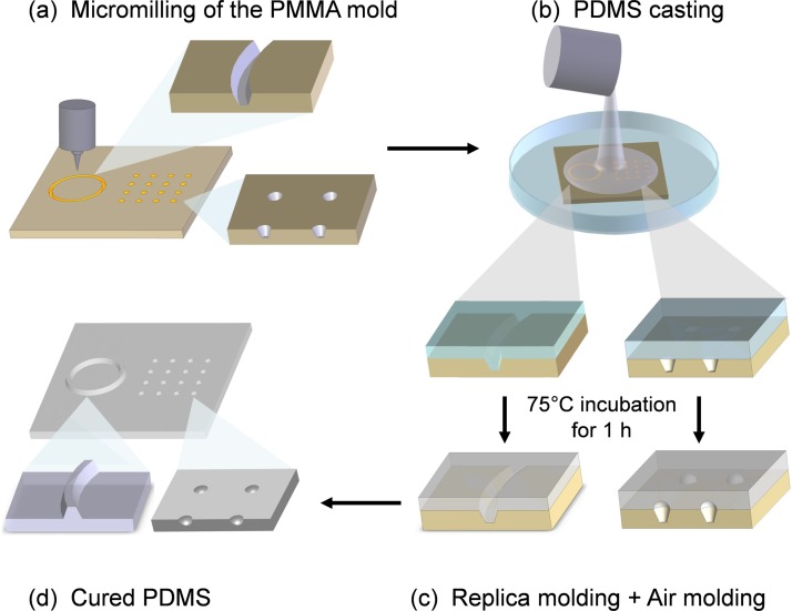
In the present study, we report another alternative approach that facilitates the rapid fabrication of microdevices with 3-D curved structures by combining replica molding and air molding. Briefly, after a polymethyl methacrylate (PMMA) mold was machined, the PDMS pre-polymer was directly poured onto it. The microchannels in the PMMA mold can easily be filled with PDMS pre-polymer, while the air-bubbles to be trapped inside the microcavities. When the replica was cured in an incubator, the PDMS pre-polymer in the microchannels polymerized and formed protruding microstructures, while the air-bubbles trapped in the microcavities on the same substrate expanded and formed concave structures via “air-molding”.14, 15, 16 The parameters affecting the molding processes were examined and modulated to produce 3-D microstructures with different shapes and sizes. To demonstrate the potential application of our method, we utilized a microfluidic device fabricated with arrays of concave microwells for the production of uniform embryoid bodies (EBs).
EXPERIMENTAL METHODS
Chemicals and reagents
Alpha minimum essential medium (α-MEM), fetal bovine serum, trypsin/EDTA solution, penicillin, and streptomycin were purchased from Gibco BRL Inc. (Grand Island, NY). Propidium iodide (PI) and calcein acetoxymethyl ester (CAM) were purchased from Invitrogen (Carlsbad, CA). PDMS (Sylgard 184) and curing agent were supplied by Dow Corning Inc. (Midland, MI). PMMA plates were supplied by Eternal Life Acryl Factory of Peking (Beijing, China). All other reagents were supplied by Sigma-Aldrich (St. Louis, MO).
PMMA mold design and micromachining
The PMMA molds consisting of microchannels and/or microwells (Fig. 1a) were machined by a computer-controlled milling machine (Hong Yang Company, Beijing, China). The customized designs were first generated in AutoCAD (Autodesk, Inc., San Rafael, CA) and saved in DXF file format. The DXF file was then loaded into the micromilling machine for direct milling and drilling.
Figure 1.
Schematic illustration for the fabrication of the protruding microstructures and the concave microstructures by combined, single-step replica molding, and air molding. (a) The PMMA mold was machined with both microwells and microchannels. (b) The PDMS pre-mixture was directly poured onto the PMMA mold. (c) The PMMA microchannels were filled with PDMS pre-mixture to produce the protruding structures, while the PMMA microwells were not filled with the PDMS pre-mixture so the air retained inside the wells would expand to produce concave PDMS microwells during incubation. The molding process applied on the same substrate was combined, single-step replica molding and air molding. (d) The cured PDMS replica with both the concave and protruding microstructures.
Fabrication of PDMS microdevices through combined replica molding and air molding
Prior to microdevice fabrication, the PDMS base and curing agent were mixed in a 10:1 ratio by weight, degassed in a vacuum, and then incubated at −20 °C before use. During the molding processes, the residual air in the PMMA microwells would expand to a certain extent and form concave microstructures in the PDMS (Figs. 1b, 1c). In our experiments, the PDMS pre-polymer mixtures were all maintained at −20 °C except the case for the “crater-like” microstructure. After pre-incubation, the PDMS pre-polymer mixture was poured onto the PMMA mold (3-mm thickness) and cured at 75 °C for 1 h in a vacuum oven (DZF-6020, Yi Heng Company, Shanghai, China).
Microscopic examination of the devices and microstructures
The geometry of the microstructures in the PDMS microdevices was assessed via scanning electron microscopy (SEM). PDMS samples were sputter coated with 10-nm gold (E1010, Hitachi, Shanghai, China), mounted onto an aluminum stage, and grounded with silver paint. Samples were then examined in the SEM (FEI Quanta 200, FEI, Shanghai, China) at 3 kV. The bright-field images of the PMMA molds and PDMS microdevices were taken using a microscope (DM-IRB, Leica, Germany) with a CCD camera (DP-71, Olympus, Japan) or a digital single lens reflex (Nikon D80, Tokyo, Japan).
Cultivation of cells in the PDMS microwells
P19 cells were obtained from the Cell Resource Center of Peking Union Medical College (PUMC, Beijing, China). The cells were incubated at 37 °C in a humidified 5% CO2 atmosphere with α-MEM supplemented with 10% fetal bovine serum, 100 units mL−1 penicillin, and 100 mg mL−1 streptomycin sulfate. To seed cells onto the PDMS microdevice with concave wells, a monodisperse cell suspension was prepared using standard tissue culture techniques with 0.25% trypsin containing 0.53 mM EDTA.
Prior to cell seeding, the microdevice was rinsed with 75% ethanol, incubated for 30 min with Pluronic F108 solution (1% w/v, dissolved in PBS) to improve the cell-repellent properties of the PDMS, and then washed with PBS buffer. After evacuating all reservoirs, cell suspension solutions at various concentrations (2-20 × 104 cells mL−1) were infused from eight inlets around the microdevice by an external syringe pump (Harvard, PHD 2000 programmable, Holliston, MA). To prevent convective effects within each microchannel, which would disrupt the uniform distribution of P19 cells, the cells were allowed to settle into the microwells at room temperature for 15 min. Then, pure α-MEM was infused with an inlet velocity of 2 mm/s to remove the excess cells that settled around the microwells, and the microdevice was placed into the cell culture incubator. The microdevice was imaged every 24 h to monitor the formation of EBs. Fluorescent reagent was added via the inlets for cell staining. In our experiments, PI (2 μM dissolved in α-MEM) and CAM (10 μM dissolved in α-MEM) were used as fluorescent probes to assess cell viability. Images were taken using a fluorescence microscope with a CCD camera.
RESULTS AND DISCUSSION
Construction of protruding and concave microstructures
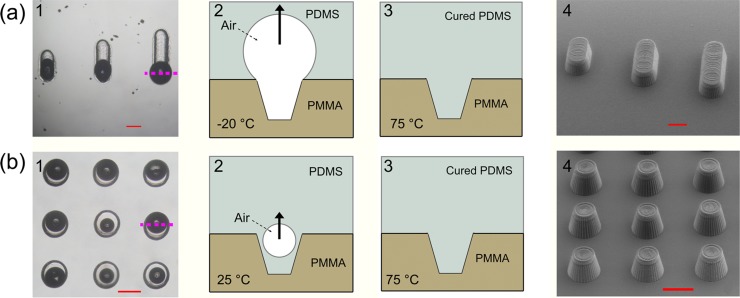
In this study, a microdevice with both concave and protruding microstructures was fabricated by combined, single-step replica molding and air molding. The overall work-flow of this integrated molding method is illustrated in Fig. 1. Conventional replica molding and air molding were combined in one step, which could be used for the simultaneous fabrication of devices with both concave and protruding microstructures. Figs. 23 explain the fabrication processes of these structures with illustrations and recorded micrographs, respectively. By carefully examining the experimental conditions (i.e., the patterns of the PMMA mold, the PDMS pre-incubation temperature, the PDMS curing temperature, and the pressure in the incubator), we found that the core of the conventional replica molding and air molding was the control of the size of the air-bubble expansion during the molding process. In the current work, the protruded structures were fabricated by conventional replica molding, and their shapes were determined by the PMMA mold. To produce a protruding wall-like structure, the air in the PMMA channel was compressed into a large air-bubble after the pre-polymer was poured onto the mold. As shown in Fig. 2a1, the PMMA microchannel had a trapezium shape. When the diameter of the air-bubble became larger than the width of the PMMA channel during casting, the air-bubble would endure an upward floating power and eventually flow away. When the residual air was driven away, the PMMA channel was completely filled with the PDMS pre-mixture. After incubation at 75 °C for 1 h, a protruding PDMS wall with a trapezium shape was obtained, as shown in Fig. 2a4. The shape of the PDMS wall was determined by the tip of the drill. Indeed, using a proper drill tip, micro-molds with cylindrical or rectangular head and tail shapes can be constructed.17, 18, 19 Because of the limitation of machining accuracy, the smallest feature diameter of the PMMA cavity was 100 μm. Additionally, when the diameter of the PMMA cavity was more than 2 mm, the surface tension was not large enough to prevent the PDMS pre-polymer mixture from dropping into the PMMA cavity. Hence, the diameter of the concave PDMS microwells obtained with our molding method works in the range from 100 μm to 2 mm in diameter.
Figure 2.
Construction of the protruding microstructures. (a-1) and (b-1) Bright-field images of the PMMA mold after PDMS pre-mixture casting. (a-2) and (b-2) Illustration of the cross-section of the PMMA molding (the purple lines in (a-1) and (b-1) indicate the sectioning position) before incubation. The air-bubbles in the PMMA microwells endure an upward floating power. (a-3) and (b-3) Illustration of a cross-section of the PMMA molding after 1 h of incubation. The air-bubbles in the PMMA microwells eventually flowed away. (a4) and (b4) SEM monographs of the protruding structures. All scale bars represent 500 µm.
Figure 3.
Construction of the concave microstructure. (a) Bright-field image of the PMMA mold after PDMS pre-mixture casting. (b) Illustration of the cross-section of the PMMA molding (the purple lines in a-1 and b-1 indicate the sectioning position) before incubation. The air-bubble residing in the PMMA microwell endured a downward pressure. (c) Cross-section of the PMMA molding after 1 h incubation. The air-bubble was sealed in the PMMA microwell and then expanded to form a concave PDMS microwell. (d) SEM image of the cured PDMS with uniform concave microwells. The scale bar represents 500 µm.
Further, we found that the PDMS pre-incubation temperature played a key role in the fabrication of a protruding cylinder structure. When the PDMS pre-mixture was incubated at 25 °C for 1 h, it had low viscosity and tended to immerge into the PMMA microwell during the casting process due to the immersional wetting. If the PDMS pre-mixture flowed into the PMMA microwell along the wall (Fig. 2b2), the residual air-bubble was driven away during incubation at 75 °C for 1 h. The cured PDMS replica with protruding cylinders is shown in Fig. 2b4.
Contrary to the situation in Fig. 2b, when the PDMS pre-mixture was incubated at lower temperatures (−20 °C in the current work), the air was sealed in the PMMA microwell and would then expand to a limited volume in the following curing process depending on the temperature applied. By following this process, concave microwells were fabricated (Fig. 3d). The features of the concave microwells were not directly determined by the shapes of the PMMA mold. The diameter of the PDMS microwells was equal to the microwells on the PMMA mold, while the aspect ratio of the PDMS microwells was affected by the aspect ratio of the PMMA microwells. The determining factors of the aspect ratio of the PDMS microwells included the pre-incubation temperature of the PDMS pre-polymer mixtures, the PDMS curing temperature, the structure of the PMMA microwells, and the air pressure difference (ΔP) between the incubator and PDMS. Here, the pre-incubation temperature determined the viscosity and the wetting property of the PDMS pre-mixture, which then affected the volume of the retained air inside the PMMA microwells. Theoretically, the higher that the PDMS curing temperature is the more the air expands, which would be propitious to improve the aspect ratio of the PDMS microwells. However, the temperature increase accelerates the curing of the PDMS pre-mixture and then shortens the time for air expansion. Therefore, the curing temperature was set at 75 °C to achieve the appropriate time needed for air to expand. Moreover, the shape of the PDMS microwells could be adjusted by ΔP.14, 15, 16 The high ΔP can be achieved by evacuating the incubator, which was beneficial to produce the PDMS microwells with high aspect ratios. However, when ΔP was >0.05 MPa, it may induce the residual air to escape from the PMMA cavities; therefore, ΔP < 0.05 MPa was allowed in our experiments.
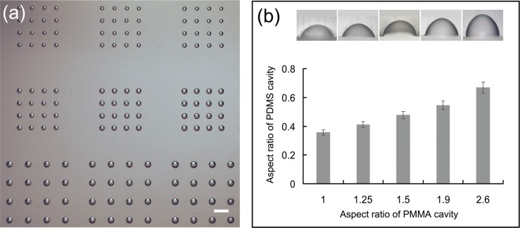
One of the main advantages of our method is that the diameter and depth of the microwells can be selectively controlled on one device simply by changing the feature size of the PMMA microwells (Fig. 4). With our method, the aspect ratio of the concave PDMS microwells can also be easily modulated by adjusting ΔP and the curing temperature; however, these two adjustments will affect the aspect ratio of all microwells without distinction, which is not beneficial for fabrication of microwells with diverse aspect ratios on one device. Therefore, in our experiment, we modulated the aspect ratios of PDMS concave microwells by changing the aspect ratios of the PMMA microwell mold while fixing the curing temperature. As shown in Fig. 4, we fabricated microwells with the same diameter but diverse depths on a PMMA mold and then produced the PDMS microwells with the aspect ratios varying from 0.356 ± 0.02 to 0.668 ± 0.04 on the same device (Fig. 4).
Figure 4.
Characterization of the molded microstructures. (a) Bright-field images of PDMS microwells with different diameters. (b) Modulation of the aspect ratio of the microwells. The aspect ratio of the PDMS microwells increased with the depth of the PMMA microwells. The bright-field images of the cross-sections of PDMS microwells with different depths (upper right insets) are arranged in order of their aspect ratio. The scale bar represents 1 mm.
Fabrication of protruding PDMS structures with concave wells
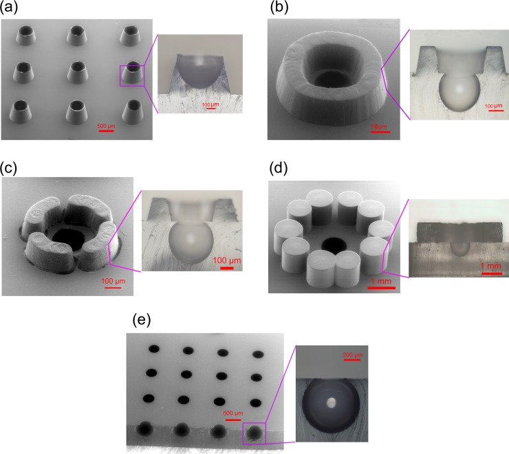
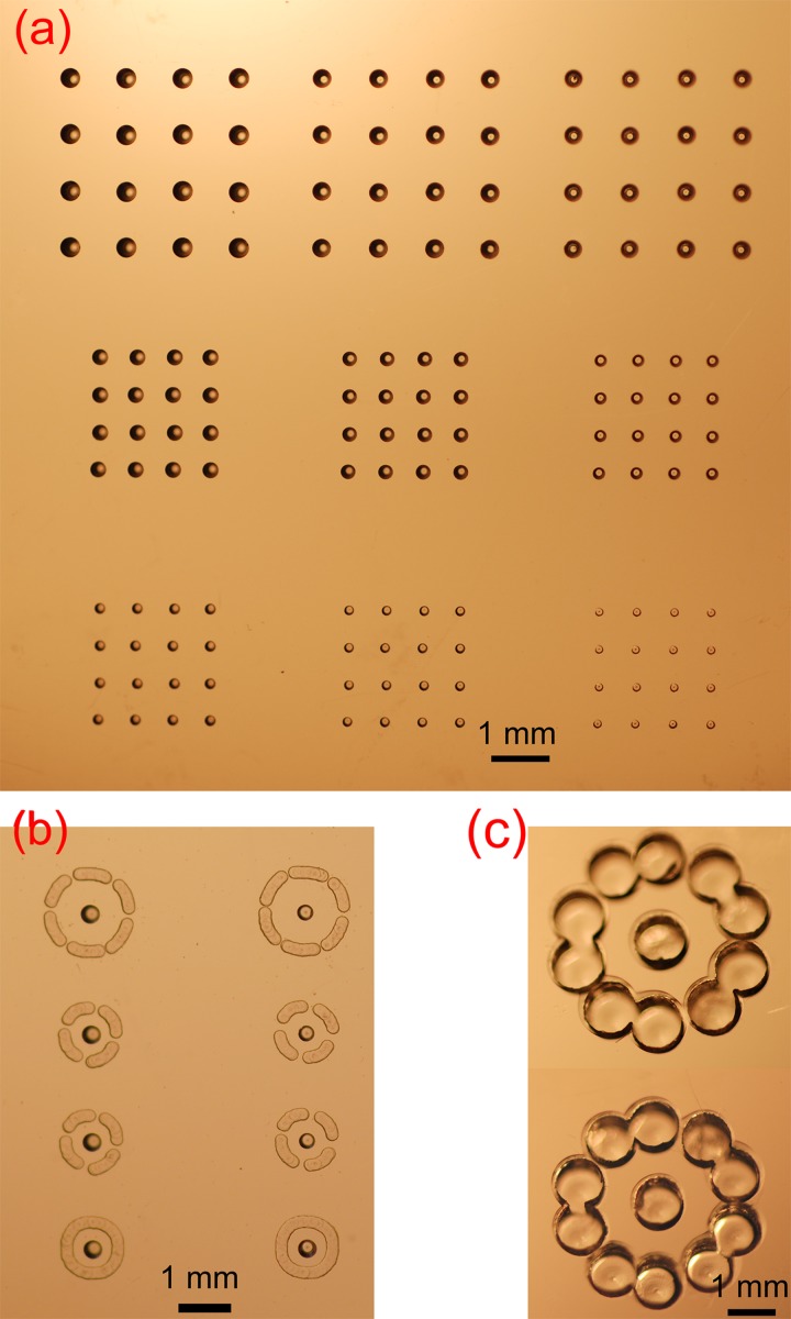
Conventional molding procedures are not suitable for simultaneous fabrication of both concave and protruding structures on the same device, but our current procedure can satisfy such a demand. As far as the viscosity of the PDMS pre-mixture can be controlled during the molding process, the air-bubbles inside the PMMA microwells can be allowed to either remain or leave, and the structures obtained can vary at a 3-D level as needed. For example, to fabricate crater-shaped concave wells (see Fig. 5a), we needed to allow the PDMS pre-mixture to sink in but not fully fill the PMMA microwells if the depth of the PMMA microwells is longer than their capillary length.20 Further, the size of the crater wall can be altered with multiple parameters (e.g., the pre-incubation and curing temperatures, as well as the pressure in the incubator). The PMMA mold for this structure is shown in Fig. 6a, and Fig. 5b shows a castle-shaped microstructure that we made. The castle structure is composed of a concave microwell in the center surrounded by a protruding cylinder. The PMMA mold for this structure was comprised of a microwell and a circular channel (Fig. 6b). Because the inner surface of the aforementioned concave microwells can be selectively modified, it may be useful for the cultivation of cells or the trapping of polymer-encapsulated chemicals in studies such as chemotaxis.
Figure 5.
Fabrication of protruding PDMS structures with concave wells. (a) Crater-shaped concave wells. (b) Castle-shaped microstructure with a closed circular cylinder. (c) and (d) Castle-shaped microstructures with separated cylindrical walls. (e) Cellar-shaped concave microwells. An enlarged image of each structure is positioned to the left of its SEM image.
Figure 6.
Photographs of the PMMA molds. (a) PMMA microwells for the fabrication of the PDMS concave microwells with different diameters. (b) and (c) PMMA mold for castle-like microstructures. All of the patterns in the PMMA plate were milled by a computer-controlled machine.
As shown in Figs. 5c, 5d, structures similar to Fig. 5b but with separated cylindrical walls were fabricated. The PMMA mold for this structure was comprised of a microwell and a few broken circular channels (Fig. 6b). The small gaps between the broken cylindrical walls were there to facilitate the exchange of nutrient components with the surrounding environment. In our previous study,21 similar structures were fabricated without the central concave microwell and used for single-oocyte positioning and early embryo development. The castle-like structure with a broken wall (similar to Figs. 5c, 5d) was demonstrated to have a better cleavage rate compared to the closed one (similar to Fig. 5b). However, the concave microwell positioned in the center of the present fence structure may accurately confine the oocyte and then further facilitate the following automated optical imaging process. Furthermore, the shape of the concave microwell was similar to the contour of the oocyte, which may provide a culture environment closer to its physical condition. Compared to the soft lithography and micro-molding procedures used in our previous study,21 the method presented here is more simple and flexible.
The microstructures shown in Fig. 5e look like cellars because of their narrow openings. When the PMMA microwells had a high aspect ratio (i.e., >2.6) or the PDMS was casted under low pressure in the incubator, the air in the PMMA microwells over-expanded and formed ultra-concave or the cellar-like microwells.
In our previous study,22 PDMS microwell arrays with rectangular geometry were fabricated for single-oocyte trapping, in vitro fertilization, and embryo culture. One of the functions for these rectangular microwells was to remove cell debris under flow. However, the dead space in the corner of the rectangular microwell endured a significant low flow velocity, which was not propitious for debris removal. The cellar-shaped microwells presented here should be helpful in solving this problem because no dead space exists in the concave microwells.
Biological testing of a microfluidic device with size-varied concave microwells
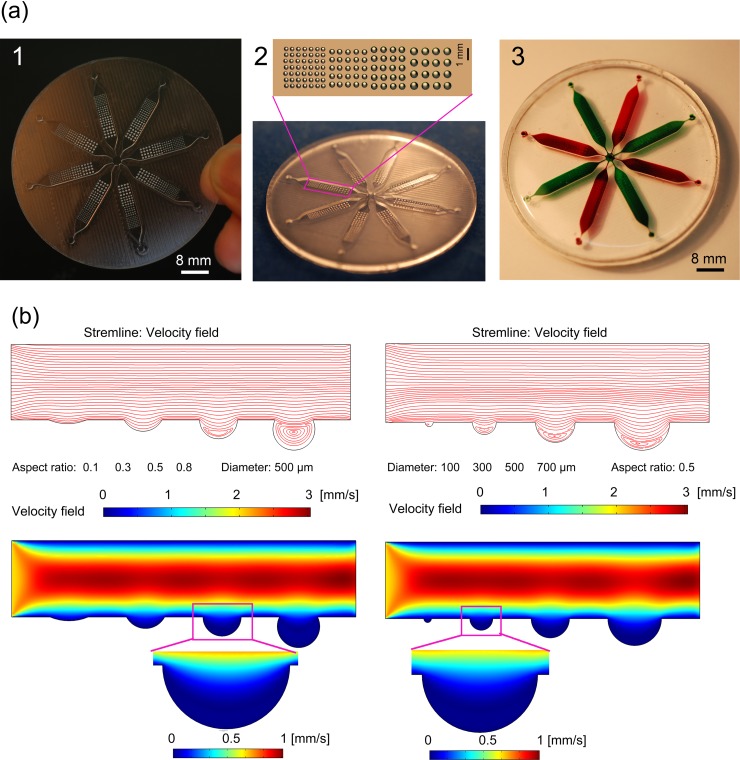
To fabricate an encapsulated microfluidic device with size-varied concave microwells, the PDMS pre-polymer mixture pre-incubated at −20 °C was directly poured onto the PMMA mold (Fig. 7a1) and incubated at 75 °C for 1 h to produce the cured PDMS layer with concave and protruding microstructures (Fig. 7a2). The cured PDMS layer was then peeled off the PMMA mold, washed with detergent and distilled water, and air-dried under a stream of nitrogen gas. Afterwards, the PDMS layer with replicated 3-D microstructures was bonded onto a featureless PDMS layer with holes drilled through it after a 20-s treatment with oxygen plasma (FEMTO, Diener Plasma-Surface-Technology, Germany) to fabricate an assembled microfluidic device (Fig. 7a3).
Figure 7.
Fabrication of the microfluidic device with arrays of concave microwells. (a) Bright-field images of the PMMA mold (left), cured PDMS replica (middle), and the fully assembled device with eight microchannels for cultivating the EBs in parallel (right). (b) The 2D computational simulation of the velocity distribution in a microchannel with various microwells. The channel flow speed was set at 2 mm s−1 from left to right. Velocity contours and streamline patterns for microwells were provided, respectively.
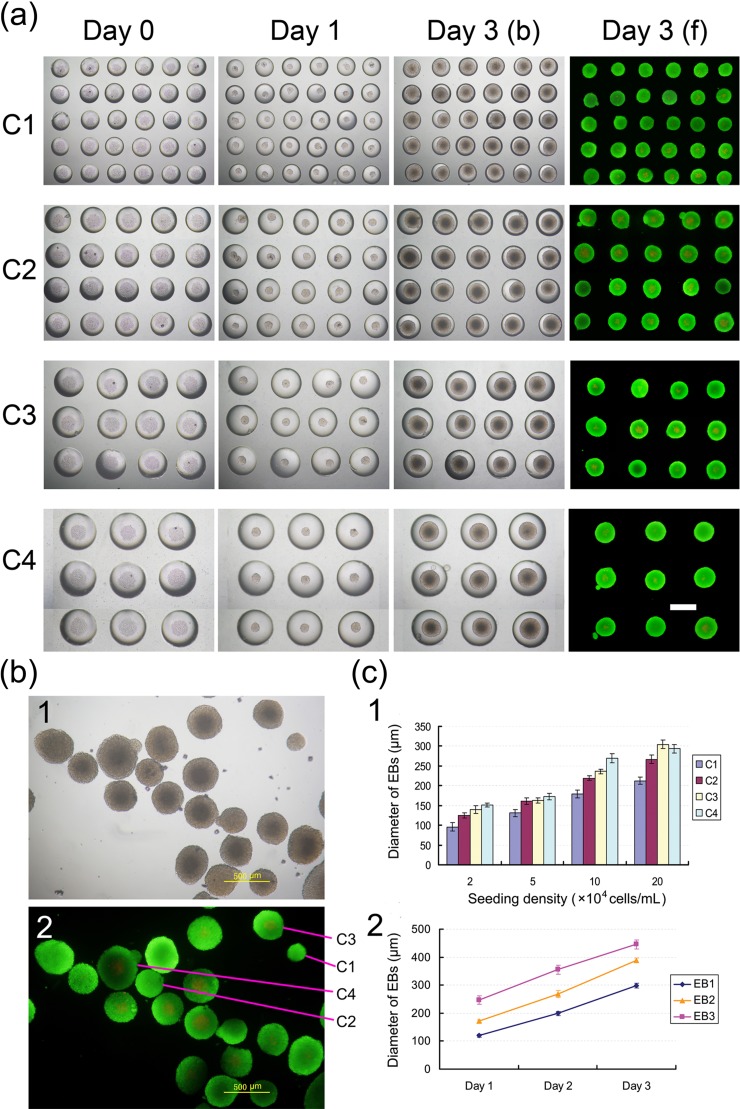
In this study, the assembled microfluidic device was tested for biological use, in particular, for the formation of EBs. The images of the PMMA mold, the casted PDMS micro-structured replica, and the assembled PDMS microfluidic device are shown in Fig. 7a. Eight parallel channels were symmetrically set and connected with the center outlet. There were four types of concave microwells with varied diameters (C1-C4: 7 × 7, 390 ± 7.7; 5 × 5, 509 ± 13.8; 5 × 4, 612 ± 13.5; 4 × 4, 741 ± 8.7 μm; mean ± SD, n = 9) and similar aspect ratios (∼0.5) positioned in each 1-mm depth channel.
To generate EBs, the concave microwells in the present microfluidic device were used to collect P19 cell aggregates under controlled conditions. Embryonic stem (ES) cells are of great interest in regenerative medicine and cell-based therapies23, 24 due to their potential for unlimited pluripotency and differentiation. Most protocols for ES cell differentiation involve the removal of self-renewing factors and the formation of EBs, which initiate many developmental processes. Therefore, EB culture has been widely utilized as the initial step for the in vitro differentiation of ES cells. EBs are generally formed through the hanging drop technique25 and suspension culture in bacteriological dishes or rotating wall vessels.26 However, these methods face challenges either in the precise control of the EB size or the promotion of the throughput. To reduce the problems associated with these standard methods, several new methods based on microwells have been developed to homogeneously form EBs and control their differentiation.27, 28, 29, 30 However, such methods require complex operations for device fabrication, and most of the devices27, 28, 29 possesses microwells with rectangular cross-sections, which have difficulty in single-EB formation in each well.30 Moreover, standard photolithography possesses the advantage of precise 2-D patterning but is limited in the fabrication of microwells with different depths in one chip. With our method, the diameter and the depth of the concave microwells can be easily modulated (Fig. 4). The total time needed for fabricating the PMMA mold, PDMS curing, and microfluidic chip assembly was <2 h.
By simultaneously seeding cells with diverse density in eight inlets around the microfluidic device (Fig. 7a3), microwells with different diameters in each channel can be filled with various numbers of cells. The presence of microwells created regions of low shear stress (Fig. 7b), which allowed the cells inside the microwells to be retained during the medium replacement and the simple washing away of excess cells outside the microwells. To better understand the flow behavior of the microwells, a computational analysis was performed using finite element models (comsol 3.5, Comsol AB, Burlington, MA), and the results are shown in Fig. 7b. In our previous study31, we found that microwells with flow microcirculation present in their bottoms are favorable for cell retention. From the results shown in Fig. 7b, the microwells with small diameters and low aspect ratios were not propitious to trap cells inside, while the microwells with high aspect ratios (>0.5) were not suitable for EB harvest. Therefore, it was clear that the microwells with diameters >300 μm and ∼0.5 aspect ratios were suitable for both the formation and harvest of the EBs. The initial cell number in the microwells was determined by the size of the concave microwells and the seeding density, and the trapped cells were cultured for 3 days to form the EBs. The diameter of the cell aggregates enlarged along with the increase of cell loading density and the diameter of the microwells (Fig. 8a).
Figure 8.
Biological testing of the microfluidic device fabricated using the current method. (a) EBs cultured within the concave microwells. Calcein AM stained the live cells (green) and PI stained the dead cells (red). The fluorescent images of EBs cultured for 3 days in the concave microwells were analyzed to assess cell viability. The scale bar represents 500 µm. (b) Images of EBs retrieved from concave microwells after growing for 4 days in vitro: (1) bright-field image and (2) fluorescent image. (c) Quantitative analysis of the diameter of the EBs: (1) analysis of the diameter of EBs within the microwells under different seeding densities after 1 day culture (C1–C4 indicate concave microwells with four different diameters); and (2) growth curves of EBs with different initial diameters.
The EB formation results and viability tests at a loading density of 5 × 10⁴ mL−1 are shown in Figs. 8a, 8b. The P19 cells aggregated together 1 day after seeding and rapidly proliferated in the following culturing processes. As shown in Fig. 8a, the live/dead cell staining results demonstrated that the cells within the EBs were viable throughout the 3-day culture period irrespective of the microwell size. The growth curves of EBs with different initial diameters (Fig. 8c) also demonstrated the good viability of EBs in our microdevice. Ultimately, EBs growing in microwells maintained their shape, viability, and a high degree of homogeneity, which may permit their future use in research or therapeutic applications.
Apart from the ease of use in cell seeding and culturing, another advantage of our microfluidic device is that the EBs can be easily retrieved from the culturing wells at any time without compromising the cell’s viability. Compared to microwells with a rectangular cross-section, the PDMS concave microwells offered a much better retrieval capability due to their round bottom and wide openings. Retrieval was even further enhanced by the excellent cell-repellant character of PDMS after F108 coating. After the 4-day cultivation period, EBs were washed out in a high flow velocity (6 mm/s) or in a low flow velocity (0.5 mm/s) when we inverted the device. Using this device, pipette-based manual cell retrieval was avoided, and the EBs could be re-plated onto tissue culture dishes when a medium replacement operation was performed (Fig. 8b).
CONCLUSIONS
In the present study, we developed a novel molding method to rapidly fabricate microdevices with curved 3-D microstructures by combining conventional replica molding and air molding in a single step. This molding method was capable of simultaneously producing both concave and protruding microstructures with 3-D topography on the same replica and allowed for rapid fabrication of microfluidic devices in a simple, rapid, and flexible manner. As a typical biological test, we designed and tested a microfluidic device generated by our method. This device was filled with arrays of size-varied concave microwells, which produced homogeneous EB sizes. The microfluidic device fabricated here may be further incorporated into much more complicated high-throughput screening systems, where generation of large numbers of homogeneous EBs may be required for therapeutic use or to simultaneously study the effects of multiple conditions on ES cells.
ACKNOWLEDGMENTS
This study was supported by a grant of the National Hi-Tech Program of China (Grant No. 2006AA020701).
References
- Xia Y. N. and Whitesides G. M., Angew. Chem., Int. Ed. 37, 551 (1998). 10.1002/(ISSN)1521-3773 [DOI] [Google Scholar]
- Wu H. K., Odom T. W., and Whitesides G. M., Anal. Chem. 74(14), 3267 (2002). 10.1021/ac020151f [DOI] [PubMed] [Google Scholar]
- Verpoorte E. and De Rooij N. F., Proc. IEEE 91(6), 930 (2003). 10.1109/JPROC.2003.813570 [DOI] [Google Scholar]
- Stroock A. D., Dertinger S. K. W., Ajdari A., Mezic I., Stone H. A., and Whitesides G. M., Science 295(5555), 647 (2002). 10.1126/science.1066238 [DOI] [PubMed] [Google Scholar]
- Barber R. W. and Emerson D. R., Microfluid. Nanofluid. 4(3), 179 (2008). 10.1007/s10404-007-0163-6 [DOI] [Google Scholar]
- Luo L. W., Teo C. Y., Ong W. L., Tang K. C., Cheow L. F., and Yobas L., J. Micromech. Microeng. 17, N107 (2007). 10.1088/0960-1317/17/12/N02 [DOI] [Google Scholar]
- Nguyen D., Sa S., Pegan J. D., Rich B., Xiang G., McCloskey K. E., Manilay J. O., and Khine M., Lab Chip 9(23), 3338 (2009). 10.1039/b914091c [DOI] [PubMed] [Google Scholar]
- Park J. Y., Hwang C. M., and Lee S. H., Biomed. Microdevices 11(1), 129 (2009). [DOI] [PubMed] [Google Scholar]
- Chao S. H., Carlson R., and Meldrum D. R., Lab Chip 7(5), 641 (2007). 10.1039/b618269k [DOI] [PubMed] [Google Scholar]
- Liu X., Wang Q., Qin J. H., and Lin B. C., Lab Chip 9(9), 1200 (2009). 10.1039/b818721e [DOI] [PubMed] [Google Scholar]
- Yi Y., Kang J. H., and Park J. K., Electrochem. Commun. 7(9), 913 (2005). 10.1016/j.elecom.2005.07.001 [DOI] [Google Scholar]
- Park J. Y., Lee D. H., Lee E. J., and Lee S. H., Lab Chip 9(14), 2043 (2009). 10.1039/b820955c [DOI] [PubMed] [Google Scholar]
- Zhang M. Y., Wu J. B., Wang L. M., Xiao K., and Wen W. J., Lab Chip 10(9), 1199 (2010). 10.1039/b923101c [DOI] [PubMed] [Google Scholar]
- Zhou M., Li J., Yan F., Fan X., and Cai L., Langmuir 26(18), 14889 (2010). 10.1021/la102427g [DOI] [PubMed] [Google Scholar]
- Cheng C. M., Matsuura K., Wang I. J., Kuroda Y., LeDuc P. R., and Naruse K., Lab Chip 9(22), 3306 (2009). 10.1039/b910826b [DOI] [PubMed] [Google Scholar]
- Giang U. B., Lee D., King M. R., and DeLouise L. A., Lab Chip 7(12), 1660 (2007). 10.1039/b714742b [DOI] [PMC free article] [PubMed] [Google Scholar]
- Wilson M. E., Kota N., Kim Y., Wang Y., Stolz D. B., LeDuc P. R., and Ozdoganlar O. B., Lab Chip 11(8), 1550 (2011). 10.1039/c0lc00561d [DOI] [PubMed] [Google Scholar]
- Okagbare P. I., Emory J. M., Datta P., Goettert J., and Soper S. A., Lab Chip 10(1), 66 (2010). 10.1039/b908759a [DOI] [PMC free article] [PubMed] [Google Scholar]
- Amberg M., Stoebenau S., and Sinzinger S., Appl. Opt. 49(22), 4326 (2010). 10.1364/AO.49.004326 [DOI] [PubMed] [Google Scholar]
- Chan-Park M. B., Yang C., Guo X., Chen L. Q., Yoon S. F., and Chun J. H., Langmuir 24(10), 5492 (2008). 10.1021/la703608p [DOI] [PubMed] [Google Scholar]
- Ma R., Xie L., Han C., Su K., Qiu T., Wang L., Huang G., Xing W., Qiao J., Wang J., and Cheng J., Anal. Chem. 83(3), 2964 (2011). 10.1021/ac103063g [DOI] [PubMed] [Google Scholar]
- Han C., Zhang Q., Ma R., Xie L., Qiu T., Wang L., Mitchelson K., Wang J., Huang G., Qiao J., and Cheng J., Lab Chip 10(21), 2848 (2010). 10.1039/c005296e [DOI] [PubMed] [Google Scholar]
- Taupin P., J. Neural Eng. 4(3), R59 (2007). 10.1088/1741-2560/4/3/R01 [DOI] [PubMed] [Google Scholar]
- Wobus M. and Boheler K. R., Physiol. Rev. 85(2), 635 (2005). 10.1152/physrev.00054.2003 [DOI] [PubMed] [Google Scholar]
- Konno T., Akita K., Kurita K., and Ito Y., J. Biosci, Bioeng. 100(1), 88 (2005). 10.1263/jbb.100.88 [DOI] [PubMed] [Google Scholar]
- Castaneda F. and Kinne R. H., J. Cancer Res. Clin. Oncol. 126(6), 305 (2000). 10.1007/s004320050348 [DOI] [PMC free article] [PubMed] [Google Scholar]
- Mohr J. C., de Pablo J. J., and Palecek S. P., Biomaterials 27(36), 6032 (2006). 10.1016/j.biomaterials.2006.07.012 [DOI] [PubMed] [Google Scholar]
- Moeller H. C., Mian M. K., Shrivastava S., Chung B. G., and Khademhosseini A., Biomaterials 29(6), 752 (2008). 10.1016/j.biomaterials.2007.10.030 [DOI] [PMC free article] [PubMed] [Google Scholar]
- Hwang Y. S., Chung B. G., Ortmann D., Hattori N., Moeller H. C., and Khademhosseini A., Proc. Natl. Acad. Sci. U.S.A. 106(40), 16978 (2009). 10.1073/pnas.0905550106 [DOI] [PMC free article] [PubMed] [Google Scholar]
- Choi Y. Y., Chung B. G., Lee D. H., Khademhosseini A., Kim J. H., and Lee S. H., Biomaterials 31(15), 4296 (2010). 10.1016/j.biomaterials.2010.01.115 [DOI] [PubMed] [Google Scholar]
- Xu Y., Yao H., Wang L., Xing W., and Cheng J., Lab Chip 11(14), 2417 (2011). 10.1039/c1lc20183b [DOI] [PubMed] [Google Scholar]


