Abstract
A 6 year old girl presented with a large osteochondroma arising from the scapula. Radiographs, CT and MRI were performed to assess the lesion and to determine whether the lesion could be safely resected. A model of the scapula was created by post-processing the DICOM file and using a 3-D printer. The CT images were segmented and the images were then manually edited using a graphics tablet, and then an STL-file was generated and a 3-D plaster model printed. The model allowed better anatomical understanding of the lesion and helped plan surgical management.
Keywords: model, anatomy, 3D printing, rapid prototyping, segmentation, 3D modelling, image processing, DICOM, surgical planning, scapular osteochondroma, diaphyseal aclasia
CASE REPORT
Imaging techniques are important to aid in the visualization of anatomy and pathology particularly in complex surgical cases.
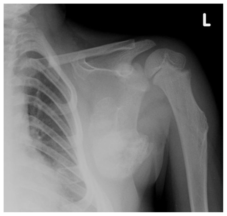
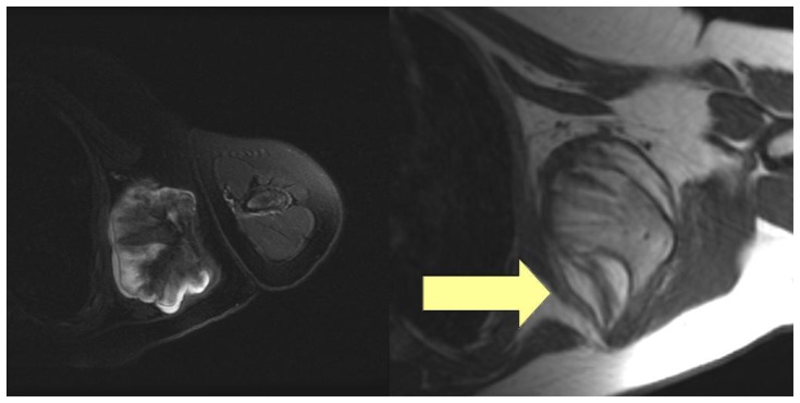
A 6 year old girl presented with a diagnosis of diaphyseal aclasia. Radiographs (Figure 1) and a Magnetic Resonance Imaging (MRI) scan (Figure 2) demonstrated multiple osteochondromata in the upper humerus, ribs, and scapula. The lesion arising from the scapula measured 6.7 cm in craniocaudal length and had maximum transverse dimensions of 7.0 × 5.5 cm. It was restricting movement, causing mass effect on the underlying thorax reducing the size of the thoracic cavity and becoming increasingly symptomatic. Potential malignant transformation in view of its size was an additional concern. The case was discussed in a multi-disciplinary team (MDT) clinico-radiological meeting with a view to proceed to resection. Excision represented a particular challenge as part of the scapula would be removed with risk of scapula winging. The precise involvement of the lesion in relation to the insertion of serratus anterior was unclear. Additionally, resection of a lesion affecting the anterior border of the scapula through the axilla is an unusual procedure and modelling could help guide the approach and minimise complications.
Figure 1.
A 6 year-old girl with a large scapular osteochondroma complicating congenital diaphyseal aclasia. Plain radiograph of the left shoulder girdle demonstrates osteochondromata arising from the scapula and also humeral shaft.
Figure 2.
A 6 year-old female with a large scapular osteochondroma complicating congenital diaphyseal aclasia. On the left, axial T2-fat saturated images demonstrate the hyperintense cartilage cap (Protocol: 1.5 T, TE 830888, TR 3960, slice thickness 5 mm, slice spacing 7 mm, matrix 0/320/256/0, echo train 16). On the right, the axial T1 weighted images with an arrow demonstrating the serratus anterior (Protocol: 1.5 T, TE 14, TR 420, slice thickness 5 mm, slice spacing 7 mm, matrix 0/256/224/0, echo train 0).
Informed consent to proceed to create a model was obtained from the parents.
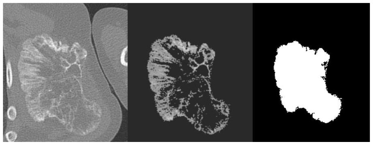
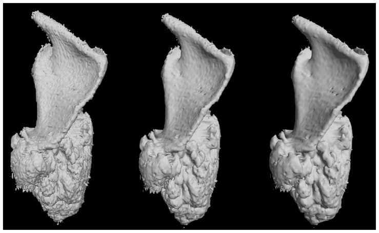
Computed Tomography (CT) was performed to provide further anatomical imaging of the left shoulder girdle and axial images were reconstructed at 1.0 mm slices with 1.0 mm slice spacing (Siemens Brilliance 64 slice CT scanner). The Digital Imaging and Communication in Medicine (DICOM) file [1] was anonymised in accordance with the parents’ wishes and was then exported from the workstation to be processed at the University. It was then uploaded into OsiriX [2]. Segmentation was performed using the threshold tool in order to convert the CT image into a black and white image. The printer required a three-dimensional (3-D) model of the surface of lesion, such as in a stereolithography (STL) file, and black and white conversion was used in order to facilitate surface extraction which would then occur at the black to white boundaries. Threshold segmentation was performed by the radiologist and pixels outside of the region of interest were converted to -1024 Hounsfield Units (HU) using upper and lower limits of 100 and 1400 HU respectively, which were arbitrarily determined by the radiologist who performed a number of iterations. Attempts to automate further processing of the DICOM into a black and white image resulted in loss of image quality and definition of the lesion edge, and so the 180 image slices were exported as graphics files, and were manually edited using a graphics tablet by a radiologist (Figure 4). The set of graphics files were then used to generate a 3-D model (Figure 5). This process was performed using a Marching Cubes algorithm which is capable of generating a polygonal model consisting of triangles to approximate a surface [3]. In this case the surface was constructed at the boundary between the white and black pixels defined in the image slices. A mean filtering algorithm was applied to the vertices of the resulting mesh to smooth out the artefacts that naturally occur in the standard Marching Cubes algorithm. At each stage of the processing, the original images were reviewed by the radiologist in tandem to determine whether the image processing retained the true likeness of the lesion.
Figure 4.
A 6 year-old girl with a large scapular osteochondroma complicating congenital diaphyseal aclasia. Stages of image-processing (a) DICOM CT image (b) threshold segmentation (c) final conversion with manual editing into a black and white STL file.
Figure 5.
A 6 year-old girl with a large scapular osteochondroma complicating congenital diaphyseal aclasia. Pre-print 3-D computer modelling with increasing number of Marching Cube algorithms applied from left to right (posterior views).
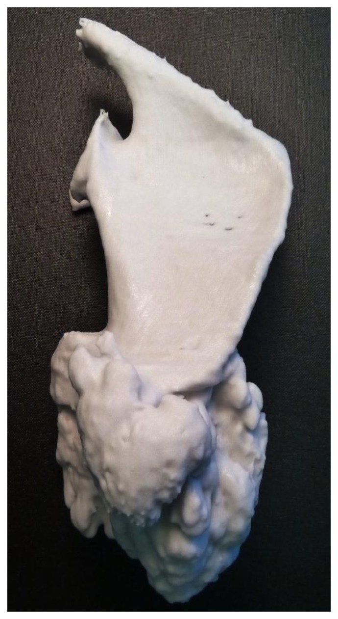
The model was then printed using a ZPrinter 450 (Z Corporation, Burlington, MA, USA). The printer essentially consists of a plaster powder piston and a building piston. The model is constructed layer by layer, with the printhead spraying binder onto the segmented area. The unbound plaster is then removed with compressed air. The print took 5 hours and the print was left overnight to settle. Cyanoacrylate was then applied to strengthen the resulting model, and the model could then be handled 24 hours after the application of glue (Figure 6).
Figure 6.
A 6 year-old girl with a large scapular osteochondroma complicating congenital diaphyseal aclasia. Photograph of the plaster model (posterior view).
Qualitative feedback was received at a subsequent MDT meeting. All surgeons, radiologists, junior trainees and allied health professionals felt that it was useful to see the model. The surgeons felt that this aided their visualization of the lesion helping plan the approach and reassure them in regard to level of serratus anterior resection.
DISCUSSION
The 3-D printout allowed accurate representation of a difficult to visualize lesion. The appreciation of the scapula can be difficult as it rarely lies on an orthogonal plane - the blade is often orientated in an oblique line. 3-D volume rendered images derived from a CT workstation are limited by being a 2-D representation of a 3-D object. Stereoscopic rendering of CT data is also possible, but this software is largely still developmental without widespread clinical use. Rapid prototyping through 3-D printing allowed the generation of a realistic, graspable, true 3-D object. The printer was able to produce a realistic model of a lesion with complex geometry which was of useful clinical value.
Limitations of the model include the possibility that any post-processing of the DICOM data and its subsequent printing would lead to significant inaccuracies. However, segmentation-based processing in this case is likely to be reasonably accurate given the inherent density of the lesion and the radiologist was involved in each step of postprocessing. The printer itself has some inherent limitations in terms of resolution (it has a minimum feature size of 0.10 mm) which is unlikely to have a major effect on accuracy given the DICOM was processed at 1 mm slices. Image smoothing algorithms were applied to make the model look more attractive, but again this could have resulted in further inaccuracy. However, many of the small undulations of the lesion may not be adequately represented because of several reasons - difficulty in extracting some of the cartilaginous components of the lesion during segmentation, and an ability to print to cope with multiple small undulations.
There are many potential further medical applications for such models which aid visualization, diagnosis, management planning, surgery, device construction [4,5,6,7] and also patient communication [8]. Further research is needed to evaluate the face validity of the printouts, as well as their clinical usefulness in helping with visualization and planning.
TEACHING POINT
Radiologists can process DICOM files and make physical models. 3-D printing can be a useful clinical tool which can be important for planning surgery or other interventions.
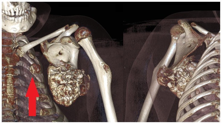
Figure 3.
A 6 year-old girl with a large scapular osteochondroma complicating congenital diaphyseal aclasia. Volume rendered images from the non-contrast CT demonstrate anterior and posterior views the lesion arising from the inferior angle of the scapula. Note also another osteochondroma arising from the 2nd anterior rib (arrow). (Protocol: 128 slice non-contrast CT, slice thickness 1mm, kVp 120, mAs 29).
Table 1.
Summary table of Diaphyseal Aclasia
| Etiology | Developmental / Bone dysplasia (solitary osteochondromas can be caused by microtrauma with transplantation of physeal tissue or be radiation-induced) |
| Incidence | 1:100,000) |
| Gender ratio | M:F 1.5:1 |
| Age predilection | 1st to 2rd decades |
| Hallmark | Cortical and marrow continuity with host bone |
| Location | Any bone which develops by enchondromal calcification (femur, tibia, humerus, hands, feet, pelvis, scapula, rib and spine in order of frequency) |
| Treatment | Resection |
| Complications | Cosmetic deformity Mechanical limitation of movement Neuropathy Reactive bursa formation Malignant transformation (1% solitary, 3 to 5% if multiple) |
| Malignant features | Cartilage cap > 1.5 cm thick Continued growth after skeletal maturation |
| Differential | Solitary osteochondroma, dysplasia epiphysealis hemimelica, Nora lesion |
Table 2.
Differential table of Diaphyseal Aclasia
| Diaphyseal aclasia | Also known as hereditary multiple exostoses, results in multiple osteochondromata, which are most commonly metaphyseal. |
| Dysplasia epiphysealis hemimelica | Also known as Trevor disease, occurs when chondromas arise from the epiphysis. |
| Nora’s lesion | Also known as bizarre parosteal osteochondromatous proliferation, normally affects the hands and feet but can also affect the long bones, and can grow rapidly and become symptomatic. |
| There is a long list of systemic disorders and developmental abnormalities which are accompanied by osteochondromas and osteochondroma-like lesions, and referral to a bone dysplasia archive, such as Taybi and Lachman’s Radiology of Syndromes, Metabolic Disorders and Skeletal Dysplasia is advised. | |
ABBREVIATIONS
- 3-D
three-dimensional
- CT
computed tomography
- DICOM
Digital Imaging and Communication in Medicine
- HU
Hounsfield Units
- MDT
multi-disciplinary team
- MRI
magnetic resonance imaging
- STL
stereolithography
REFERENCES
- 1.Graham RN, Perriss RW, Scarsbrook AF. DICOM demystified: a review of digital file formats and their use in radiological practice. Clin Radiol. 2005;60(11):1133–40. doi: 10.1016/j.crad.2005.07.003. [DOI] [PubMed] [Google Scholar]
- 2.Rosset A, Spadola L, Ratib O. OsiriX: an open-source software for navigating in multidimensional DICOM images. J Digit Imaging. 2004;17(3):205–216. doi: 10.1007/s10278-004-1014-6. [DOI] [PMC free article] [PubMed] [Google Scholar]
- 3.Lorensen W, Cline H. Marching cubes: A high resolution 3D surface construction algorithm. SIGGRAPH Comput Graph. 1987;21(4):163–169. [Google Scholar]
- 4.Rengier F, Mehndiratta A, von Tengg-Kobligk H, Zechmann CM, Unterhinninghofen R, Kauczor HU, Giesel FL. 3D printing based on imaging data: review of medical applications. Int J Comput Assist Radiol Surg. 2010;5(4):335–41. doi: 10.1007/s11548-010-0476-x. [DOI] [PubMed] [Google Scholar]
- 5.Jacobs S, Grunert R, Mohr F, Falk V. 3D-Imaging of cardiac structures using 3D heart models for planning in heart surgery: a preliminary study. Interactive CardioVascular and Thoracic Surgery. 2008;7:6–9. doi: 10.1510/icvts.2007.156588. [DOI] [PubMed] [Google Scholar]
- 6.McGurk M, Amis AA, Potamianos P, Goodger NM. Rapid prototyping techniques for anatomical modelling in medicine. Ann R Coll Surg Engl. 1997;79(3):169–174. [PMC free article] [PubMed] [Google Scholar]
- 7.Webb PA. A review of rapid prototyping (RP) techniques in the medical and biomedical sector. J Med Eng Technol. 2001;24(4):149–153. doi: 10.1080/03091900050163427. [DOI] [PubMed] [Google Scholar]
- 8.Esses SJ, Berman P, Bloom AI, Sosna J. Clinical applications of physical 3D models derived from MDCT data and created by rapid prototyping. Am J Roentgenol. 2011;196(6):W683–688. doi: 10.2214/AJR.10.5681. [DOI] [PubMed] [Google Scholar]


