Abstract
High speed Optical Coherence Tomography (OCT) has made it possible to rapidly capture densely sampled 3D volume data. One key application is the acquisition of high quality in vivo volumetric data sets of the human retina. Since the volume is acquired in a few seconds, eye movement during the scan process leads to distortion, which limits the accuracy of quantitative measurements using 3D OCT data. In this paper, we present a novel software based method to correct motion artifacts in OCT raster scans. Motion compensation is performed retrospectively using image registration algorithms on the OCT data sets themselves. Multiple, successively acquired volume scans with orthogonal fast scan directions are registered retrospectively in order to estimate and correct eye motion. Registration is performed by optimizing a large scale numerical problem as given by a global objective function using one dense displacement field for each input volume and special regularization based on the time structure of the acquisition process. After optimization, each volume is undistorted and a single merged volume is constructed that has superior signal quality compared to the input volumes. Experiments were performed using 3D OCT data from the macula and optic nerve head acquired with a high-speed ultra-high resolution 850 nm spectral OCT as well as wide field data acquired with a 1050 nm swept source OCT instrument. Evaluation of registration performance and result stability as well as visual inspection shows that the algorithm can correct for motion in all three dimensions and on a per A-scan basis. Corrected volumes do not show visible motion artifacts. In addition, merging multiple motion corrected and registered volumes leads to improved signal quality. These results demonstrate that motion correction and merging improves image quality and should also improve morphometric measurement accuracy from volumetric OCT data.
OCIS codes: (170.4500) Optical coherence tomography, (170.4470) Ophthalmology, (100.2980) Image enhancement, (100.5010) Pattern recognition
1. Introduction
Optical Coherence Tomography (OCT) [1] has become an increasingly important tool for medical imaging and biomedical research, enabling visualization of the internal structure and morphology of tissue in vivo with micron scale resolution. OCT enables structural and quantitative imaging of the retina and other tissues to diagnose disease and guide therapy [2]. As an example, glaucoma, a leading cause of blindness, is associated with retinal nerve fiber atrophy. OCT can quantitatively measure changes in the retinal nerve fiber layer thickness, enabling diagnosis of glaucoma as well as assessment of progression and response to therapy.
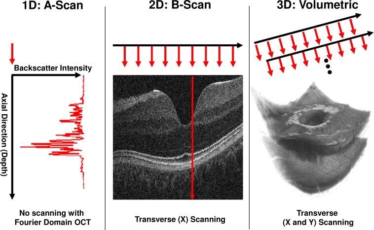
Spectral and swept source/Fourier domain OCT [3–7] have enabled significant improvements in imaging speeds, such that densely sampled of 3D volumes can be acquired in a few seconds [8]. In Fourier domain detection, the interference signal between backscattered light from the tissue and a reference path is Fourier transformed to construct axial depth profiles or axial scans of backscattered intensity. A volume is usually generated as a two dimensional grid of axial scans. The OCT beam is scanned over a region of interest on the tissue while sequentially acquiring axial scans. A typical scan pattern acquires the two dimensional grid as a collection of linear one dimensional scan lines, or B-Scans corresponding to 2D cross-sectional images using a raster scan pattern. Figure 1 illustrates OCT scanning. Using Fourier domain detection, scan rates ranging from ~25,000 to ~300,000 axial scans per second can be achieved with a trade-off between speed and sensitivity [8]. For example, using a 100 kHz axial scan rate a 400 x 400 raster of axial scans can be acquired in ~1.9 seconds, including scanner flyback time. Recently, OCT acquisition speeds of up to 1.37 million axial scans per second have been demonstrated for retinal imaging [9]. Three-dimensional data sets acquired at these fast speeds still show residual motion artifacts, suggesting that increasing OCT speeds alone is not sufficient to overcome head and eye motion induced distortions in densely scanned 3D data sets. This is because one generally wants to use increases in speed to sample more densely and/or to sample a larger area. Motion artifacts can be reduced only when increases in speed are used to decrease total acquisition time rather than increase the size of the data set.
Fig. 1.
OCT Scanning and scanner coordinate system schematic. Left: 1D acquisition (A-scan). A single depth profile is acquired which measures backscattered intensity vs. axial dimension (depth). Middle: 2D imaging (B-scan). The OCT beam is scanned in a transverse direction while A-scans (red arrows) are acquired. Right: 3D acquisition. Multiple B-Scans are acquired such that A-scans are sampled on a 2D grid in the transverse plane.
Because the axial scans comprising three-dimensional volumes are acquired over time, any movement between the OCT device and tissue results in motion artifacts. The main sources of motion are from heartbeat and respiration, which primarily manifest as motion in the axial direction. There is also motion in the transverse directions consisting of relatively slow drift and fast, large scale movements from fixation changes called saccades [10]. These movements lead to a distortion of the volume data compared with the case where there is no movement during acquisition. This differs from geometric distortion which is caused by optics of the instrument and eye. In motion distorted data, some areas of tissue might be sampled multiple times, while others might not be sampled at all, generating gaps in the data. Also, the general structure and topography of the tissue in the acquired volume might not accurately correspond to the real tissue. Motion artifacts are a significant problem for ophthalmic OCT imaging and limit the reproducibility of quantitative measurements [11].
Previous methods to solve the motion artifact problem can be characterized based on the data they operate on, whether they require additional hardware and what types of motion they can compensate. Swanson et al. [12] used cross-correlation of successive axial scans in time domain OCT to measure axial eye motion and register axial scans. This method only compensated for axial motion but did not require additional hardware. Zawadzki et al. [13] and Potsaid et al. [8] used orthogonal B-Scans scans to register the axial dimension of raster scanned 3D-OCT data. This method registers axial position, but does not correct for transverse motion. Potsaid et al. also measured eye motion and showed that transverse eye motion had a rapid +/− 20 µm component from ocular tremor and axial motion had a +/− 50 µm component associated with heartbeat. Jørgensen et al. [14] used a regularized dynamic programming approach to register multiple OCT volumes with each other in order to improve the signal to noise ratio. The technique can correct for axial motion as well as for small motion in the traverse direction. Ricco et al. [9] used an SLO reference image that is captured immediately after OCT acquisition and demonstrated an elastic image registration method to reduce vessel discontinuities which result from motion during an OCT scan. Additionally, dynamic time warping was employed to align both data sets. This method can correct motion in the transverse directions only and uses additional image information from a different modality. This requires more hardware compared with a normal OCT system. Tolliver et al. [15] used OCT raster scans with orthogonal fast scan directions. First, shift invariant 1D Haar features from each individual axial scan were generated. Then a classifier was trained to find possible matches between axial scans. Using Bayes-Filtering, a smooth path through the image was found from the match probabilities that also permitted discontinuities from saccades. Finally, eye tracking hardware can be used to directly measure and correct for eye movement [16,17]. However, eye tracking adds complexity and cost to an OCT system, and commercial systems which use SLO images for tracking, cannot track motion at the same speed that axial scans are acquired.
In this paper, we present a method to estimate and correct relative motion between the instrument and scanned tissue in all three dimensions on a per A-scan basis. The approach only requires OCT raster scanned 3D data without the need for additional tracking hardware or images from different modalities. Two or more sequentially acquired raster scanned OCT volumes are used as input data. At least two of these volumes should be scanned using raster scans with orthogonal fast scan axes, so that motion effects on the data volumes are uncorrelated. After motion estimation and correction using image registration techniques, the set of corrected volumes are combined to obtain a single volume with improved signal quality.
2. Methods
2.1. Scan process modeling
A model of the scan process is used to formulate and treat the problem of motion artifacts in OCT volumes. An A-scan can be modeled as a function of space and time:
| , | (1) |
where (p is a column vector, T denotes transpose) describes the position of the OCT beam in a device-centric scan coordinate system and tis the time when the axial scan was acquired. The above A-scan function returns a d-dimensional vector of intensities spaced in the axial direction, where d is the number of pixels of an A-Scan. The intensities depend on the scattering properties of the tissue. This model assumes that each A-scan is acquired nearly instantaneously, consistent with Fourier domain detection. The model also assumes that for a certain transverse position on the retina, the OCT beam will traverse the retina coming from the same perspective and does not have a large change in tilt through the retina produced by motion. This is equivalent to assuming that motion does not cause a significant change in the scan pivot position of the beam.
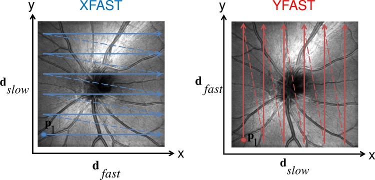
The acquisition process for 3D OCT volumes can be described by the sequence of A-scan functions at specific positions and corresponding times where where is the total number of A-scans in the volume. This sequence of positions and associated times determines the acquisition scan pattern of a volume. Although the motion correction methods can work with many types of scan patterns, for simplicity, this work uses raster scan type 3D volumes with isotropic sampling in both transverse directions, as shown in Fig. 2 . This scan pattern can be described using a transverse fast direction vector corresponding to the direction of the B-scans and an orthogonal slow direction vector . The volume is acquired by linearly scanning the OCT beam along the fast direction while acquiring A-scans to generate 2D cross-sectional scans or B-scans. After each B-scan, the scanner quickly moves back (flyback) to its starting position along while also moving one raster step along the slow scan direction. This process is repeated several times until the entire scan area has been scanned and the 3D volume data acquired.
Fig. 2.
Schematic of XFAST/YFAST raster scan. Solid arrows indicate B-scan acqusitions, dotted arrows indicate flyback. Left: An XFAST scan consists of B-scans parallel to the x-axis in the OCT scanner coordinate system. An YFAST scan (right) consists of B-scans parallel to the y-axis. and are interchanged between the two scan types. In both cases, the A-scan sampling locations form a 2D grid in the transverse plane of the scanner coordinate system. The transverse position of the first A-scan is shown for each pattern.
The scan patterns are chosen such that the set of sampled positions in the scanner coordinate system are the same. However, the order in which these points are sampled should be different. For optimal performance, at least two of the input volumes should have scan patterns where the fast and slow directions are orthogonal to each other. This implies that the fast direction in one scan pattern is the slow in the other and vice versa. The respective fast scan direction contains less motion artifacts than the slow direction. In orthogonal volumes, each of the two principal transverse directions coincides with the fast direction in one of the scan patterns. Therefore, each orthogonal volume provides a relatively accurate depiction of the object structure along one direction. In this paper orthogonal volumes are used to construct a volume that is considered more accurate and less affected by motion artifacts in all three spatial directions. A raster scan pattern where the x direction is scanned fast is called a XFAST type volume. When the y direction is scanned fast, the scan pattern is called YFAST.
2.2. Modeling motion
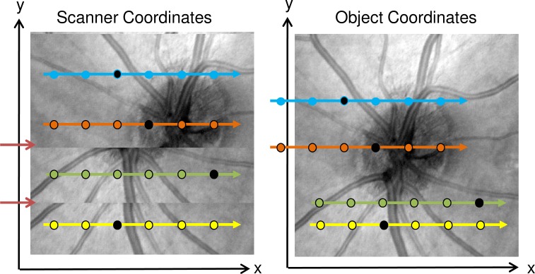
Acquiring all the A-Scans that make up an OCT volume may require a few seconds, depending on scan speed and the number of A-Scans in the sampling grid. Acquisition time is limited by eye motion, blinking and tear film stability [18]. Motion artifacts occur because motion causes the sampling position of an A-scan in the device centric scanning coordinate system to be inconsistently oriented with respect to the object coordinate system. We define the object coordinate system to be the scanner coordinate system without the effects of motion. This is not to be confused with the physical coordinate system of the object. If there is no motion during OCT acquisition, the object and the scanner coordinate systems are in alignment. Motion can cause some areas of the object to be sampled multiple times during acquisition, while other areas may be unsampled as shown in Fig. 3 . In the model the result of relative motion between the instrument and object tissue can be expressed as a function of time, which produces a 3D vector describing the relative position between scanner and object coordinate systems, i.e.,
Fig. 3.
Schematic showing relation between object and scanner coordinate system when affected by motion in the transverse plane. Left: En face view in the scanner coordinate system. Dotted arrows indicate B-scans, dots indicate individual A-scans. The background shows an en face fundus projection as it would be acquired given motion. The two red arrows indicate discontinuities from motion. Right: En face view in the object coordinate system. Arrows colored with the same color as left indicate where B-scans from the scanner coordinate system are located in the object coordinate system. The background shows an en face view of the object in the object coordinate system. Individual black dots on each B-Scan indicate corresponding A-Scans in the two coordinate systems. For corresponding A-scans, the position difference in the object and scanner coordinate system is Disp(t) at the corresponding time.
| (2) |
Using this position offset or displacement, the A-scan function at a certain time t can be referenced to a fixed point in time , where there is no relative motion, because motion requires time to pass:
| (3) |
Without loss of generality, it can be assumed that, i.e., the coordinate systems of scanner and object are aligned at. In this case, the expression reduces to
| (4) |
The displacement field function models relative motion between the scanner and object. For example, if there was no relative motion during the acquisition of a single volume, the displacement would be a constant vector during the time corresponding to the respective volume acquisition. A change in corresponds to a change in relative position between object and scanner coordinate system and therefore models the motion.
2.3. Resampling
To construct motion corrected object space volumes it is necessary to calculate for a set of positions that constitute a 2-D grid in the object space. Define a function which interpolates an input volume such that
| (5) |
The function interpolates the corresponding input volume at the original scanner space sample locations. Between sample grid positions, the function smoothly interpolates the input volume to produce intermediate virtual A-Scans. Disp(t) can be moved to the left side of the equation:
| (6) |
where is an error vector resulting from interpolation between the grid points of the input volume. Since A-Scan grid samples the tissue area densely, in this paper we assume that the magnitude of is similar to other noise sources in the OCT system and choose not to model its effects. This is a simplification, as severe motion or lack of overlap between the volumes that are to be registered can lead to high interpolation errors. However, the merging process that we propose later is designed to alleviate such effects. Given for all grid points, an approximation of the volume data in the object coordinate system can be constructed by resampling the input volume data.
2.4. Objective function
Two or more OCT volumes of an object are sequentially acquired where at least one volume has a scan pattern with a fast direction orthogonal to the other volumes. The goal for relative motion correction is then based on estimating the unknown motion as modeled by Disp(t). In order to estimate Disp(t), a global objective function based approach that consists of two objectives is used. First, after motion correcting each input volume using suitable displacement values, the resulting volumes should be similar to each other. Second, a certain smoothness of Disp(t) over short time frames is required. These two, possibly conflicting objectives are weighted against each other and combined into an objective function.
The first objective is formulated as minimizing the sum of the squared L2 norm on the pair-wise residuals between the input volumes with index v1 and v2, over a number of volume pairings. A residual volume is generated by resampling the two volumes according to the current estimates of (see Eq. (6)) and then calculating the difference between them. For re-sampling of the original volumes, cubic Hermite spline interpolation [19] is employed.
For the case of two input volumes, only one residual is needed. In the case that more than two input volumes are acquired, only a subset of all possible pairings between input volumes is used to generate the residuals. Rather than having order pairings for input volumes, only order pairings are used, resulting in significant computational savings. For this subset, pairings between volumes with orthogonal fast scan axes are preferred. The pairings should be chosen in such a way that the undirected graph formed by the volumes (nodes) and pairings (edges) is connected. If the volumes are not connected through the objective function, they will not be registered to a common space.
The second objective is motivated as follows. Assuming that the effect of relative motion is predominantly a translation of the A-Scans within the object space (i.e. the retina) and that there is no significant rotation between the object and the scanner around the optical axis during acquisition, Disp(t) must possess a certain degree of smoothness in time because it describes the relative position between scanner and object. The time derivative of Disp(t) corresponds to the relative velocity. Since the dynamics are physically constrained, the relative acceleration should have an upper bound. In addition, knowledge about the nature of the motion that occurs also places an upper bound on the relative velocity. For example, motion from respiration is assumed to be smooth, periodic and low velocity, on a millisecond time scale. This leads to the concept of enforcing a certain smoothness of the displacement function with respect to time as the second objective. The objective is expressed by minimizing a finite difference approximation of the integral of the squared magnitude of the derivative of Disp(t) with respect to time, integrated over time. This term penalizes high displacement differences within one time step disproportionally and therefore will tend to favor the modeling of smooth motion. This term, which enforces a certain smoothness of the solution, is called the regularizer.
Combining both goals into a single objective function yields
| (7) |
where v1 and v2 are volume indices ranging from 1 to the number of input volumes . The first term on the right of the equations acts as the volume similarity goal consisting of the residuals , while the second term acts as a regularizer that controls the smoothness of the displacement field with respect to time. is either 0 or 1, depending on whether a certain pairing of input volumes contributes to the objective function. α acts as a weighting factor between the two goals. To further control the registration process, an additional parameter is introduced which provides a relative scaling of the axial component of the regularization term. This enables transverse motion to be treated differently than axial motion and is helpful because OCT retinal images are often scaled differently in the axial and transverse directions and axial and transverse motion have different characteristics.
2.5. Optimization and multi-resolution technique
In order to estimate the unknown motion, the objective function should be minimized according to a finite parameter set given by the values of at all A-scan time points. This optimization problem is nonlinear and large scale. For example, registering two sequentially acquired volumes consisting of 400 by 400 A-scans each requires an objective function with unknown variables. For this reason and because an iterative numerical optimizer will in general only reach a local minimum of this non-convex objective function, a technique such as multi-resolution optimization is required [20,21].
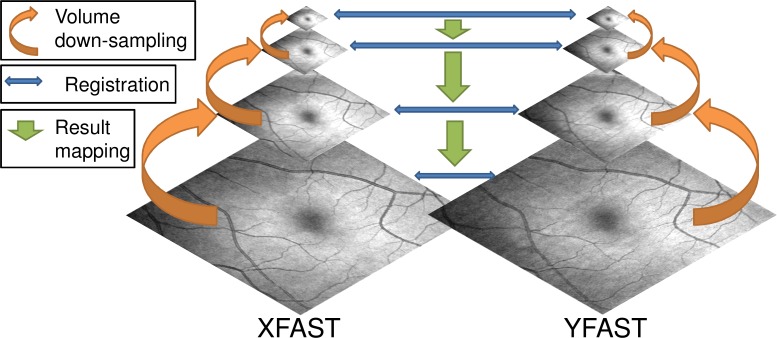
A so called “resolution pyramid” is generated by recursively down-sampling the input volumes by a factor of 2 in each direction using Gaussian reduction [22]. Lower resolution representations of the problem parameterization are generated corresponding to the lower resolution pyramid levels. This involves treating the time information, which exists on the A-scan grid, as a 2D image and successively down sampling it using Gaussian reduction. Starting from the lowest resolution approximation, each resolution level is optimized and the resulting parameter set converted to an initialization for the next level, which possesses higher resolution. The conversion is performed by again treating the displacement field as a 2D image in the A-scan grid and resampling it to the higher resolution A-scan grid of the next resolution level using bilinear interpolation. This process is repeated until the original problem complexity has been optimized. Figure 4 illustrates the concept of multi-resolution optimization.
Fig. 4.
Schematic showing multi-resolution optimization for two orthogonal volumes represented by their en face fundus projections. First, each volume is successively down-sampled to create a multi-resolution image pyramid (orange arrows). Then, starting with the lowest resolution volumes, corresponding volumes are registered (blue arrows). The registration result is then mapped to the next higher resolution pyramid level (green arrows). This is repeated until the original resolution levels are registered.
At each multi-resolution level, numerical optimization is performed until convergence is reached or until a certain iteration number budget is reached. A gradient based, quasi Newton optimizer, the limited memory Broyden–Fletcher–Goldfarb–Shanno or L-BFGS is used [23].
2.6. Pre-processing
Before beginning multi-resolution optimization, multiple pre-processing steps are performed on the input volumes to increase execution speed and improve results. First, speckle noise is reduced by 1D median filtering each A-scan. Then, the A-scans can optionally be down-sampled in axial direction by a factor of 2. Also, intensity is normalized, such that the mean intensity of each volume is 0 and the variance is 1. This alleviates potential global brightness differences and causes the volume similarity contribution in the objective function to be in a defined range. These pre-processed volumes are used to construct the volume pyramids and are ultimately resampled within the objective function to compute the volume residuals.
2.7. Volume merging
After optimization of the original objective function is finished, the final values of the displacement field function are used to synthesize registered volumes. Generating the registered volumes involves resampling the original input volume data in an analogous manner to the resampling performed when computing residuals in the objective function. Since the volumes now exist in the same motion corrected space, the voxel values can be combined in order to improve signal quality. Because of motion, some areas of an object may not have been sampled in one or more of the input volumes. Therefore, instead of simple averaging, the volumes are combined using a weighted sum, calculating the weights on a per voxel basis. During optimization, missing data is interpolated using values from neighboring A-scans. In this case, these neighboring A-scans are used multiple times, once at the real position of the A-scan in object space, and one or more times to interpolate unsampled areas.
This method is used to create the weights for combining the registered volumes. The number of times each voxel in the input volumes was used during generation of the registered volumes is calculated. Looking at corresponding voxels in the registered volumes that are to be combined, the weights are generated using this “sampling density”. The higher this value relative to values from the other voxels, the lower the weight assigned to it. If the sampling densities for corresponding locations are equal, then the weighting scheme will result in normal averaging. In a second step, weights that are significantly lower than equal share are set to zero. Afterwards, the weights are renormalized so that the sum for each set of corresponding voxels is 1. Finally, the registered volumes are combined using a voxel-wise weighted sum according to the determined weights.
3. Evaluation and discussion
3.1. Data sets used/testing protocol
The study protocol was approved by the Committee on Use of Humans as Experimental Subjects (COUHES) at MIT and informed consent was obtained prior to enrollment. In order to develop the registration and motion correction, healthy subjects were imaged in multiple sessions using two different OCT devices. System A is a 850 nm spectral OCT prototype with 3 um axial resolution operating at 70 kHz A-scan rate [8]. System B is a 1050 nm swept source OCT prototype with 7 um axial resolution operating at 200 kHz A-scan rate [24]. The high speed of this system enables acquisition of densely sampled, wide field 12 by 12 mm volumes that contain both the optic nerve head and macula. Table 1 summarizes the characteristics of each system. For evaluation purposes, each subject was sequentially imaged multiple times within a short time interval using raster scan patterns with alternating XFAST/YFAST pattern types. After each volume acquisition, the subject could blink, however the instrument alignment was unchanged. This provides multiple orthogonal OCT volumes of essentially the same physical volume.
Table 1. Characteristics of Imaging Devices.
| OCT instrument |
||
|---|---|---|
| A (UHR 850 nm spectral) | B (1050 nm swept source) | |
| Axial scan rate | 70,000 Hz | 200,000 Hz |
| Sensitivity | 97 dB | 95 dB |
| Axial resolution in air | 3 um | 7.1 um |
| Central wavelength | 825 nm | 1050 nm |
| Wavelength range | 750 nm – 900 nm | 990 nm – 1090 nm |
| Incident power to eye | 750 uW | 1.9 mW |
Table 2 summarizes the data that was acquired in the three different imaging sessions and used to evaluate the registration algorithm. The OCT instruments were aligned to maximize signal levels and avoid pupil vignetting. In addition, the beam was aligned with the pupil so that the input volumes had minimal tilting due to perspective changes. Registration was performed on a 64-bit PC with Core i7 2600K CPU, 16 GB RAM and a NVIDIA GeForce 580 GTX GPU. Parts of the calculations such as volume interpolation and residual computation were performed on the GPU. Table 2 also lists the typical time to register and merge two volumes for each imaging session. The execution time scales primarily with the total number of voxels in the input volumes. Although the algorithm already makes use of multi-threading and GPU acceleration, the execution time should be reduced further to allow seamless integration into a typical ophthalmology clinical workflow.
Table 2. Imaging Session Description.
| Imaging Session |
|||
|---|---|---|---|
| IS1 | IS2 | IS3 | |
| OCT instrument | A (UHR 850 nm spectral) | A (UHR 850 nm spectral) | B (1050 nm swept source) |
| Eye region | Optic Nerve Head | Macula | Central retina |
| Scan area | 6 mm x 6 mm | 6 mm x 6 mm | 12 mm x 12 mm |
| A-scan sampling | 400 x 400 | 400 x 400 | 1100 x 1100 |
| Axial pixels after cropping | 1000 | 800 | 460 |
| Acquisition time/volume | 2.5 seconds | 2.5 seconds | 6.4 seconds |
| Time to register volume pair | 3 minutes | 2:30 minutes | 15 minutes |
For preprocessing, a one-dimensional median filter in axial direction of five pixels was used. All data was also preprocessed by down-sampling by factor of two in axial direction. Multi-resolution optimization was performed using five resolution levels. To constrain the execution time of the algorithm, the maximum number of objective function evaluations was set to 120, 600, 3,000 15,000 and 75,000 for the different resolution levels, from original to lower resolution. The different data sets were fully automatically processed using the same settings.
3.2 Registration performance
One basic requirement for algorithm performance is that features in the motion corrected volumes, such as blood vessels and layer boundaries should be well registered with each other. To automatically and quantitatively evaluate this goal, mutual information (MI) [25] was used to measure similarity. A comparison of this MI measure before and after registration, i.e. an increase in MI, is used to assess increase of similarity between the registered volumes. However, a high similarity alone does not guarantee a good registration result. It is also important that the registration preserves, or in the case of motion, recovers the actual structure of the tissue.
Automated evaluation of this goal is difficult because the algorithm works without a ground truth, a motion free reference volume. Therefore, we employ an evaluation strategy consisting of two parts. First, the increase of similarity through registration is evaluated. Second, using 3D-3D quasi-rigid registrations of multiple disjoint volumes from the same object, the stability of the results and their dependence on algorithm parameters is evaluated. To assess stability, two merged volumes that were generated by motion correcting and merging an XFAST/YFAST pair are registered in 3D. The merged volumes do not share the same input volumes, i.e. there are disjoint sets of input volumes. The corresponding two XFAST input volumes are motion corrected in a basic way in the axial direction by correlating neighboring B-Scans within the volume and also quasi-rigidly registered in 3D. The difference in mutual information after registration of the merged volumes to the mutual information of the XFAST input volumes is computed. The mean of this measure over multiple disjoint volume pairs of an object is called stability index. It indicates how well motion correction results from disjoint sets agree on the 3D shape of the volume for given motion correction algorithm parameters.
The 3D-3D quasi-rigid registration is performed by fixing one volume and transforming the other in 3D in order to minimize the sum of squared difference of image intensity using multi-resolution optimization. The transform is parameterized by translation in all 3 directions, rotation around z and tilts in x and y. The tilt parameters model a linear shift in axial position as a function of x and y, respectively. This is used to model a tilt in the volumes that appears when the beam passes through a different position on the pupil plane. Since OCT images are typically displayed with a stretched aspect ratio in the axial or z direction in order to visualize retinal features, tilt effects are enhanced in the images. Because of these tilt parameters, the registration is strictly speaking not rigid, but affine. In the scenario of OCT imaging of the retina we deem this transform to be able to model the non-motion induced changes (global translation, tilt, rotation around the optical axis) between two volumes in a reasonably correct way and therefore this is called quasi-rigid registration.
The two key registration parameters are the general regularization strength α, which is varied from 0.0001 to 10.0 in six steps and the relative axial regularization strength , for which three settings of 0.1, 1.0 and 10.0 are heuristically evaluated. All combinations of these two parameters were evaluated for all consecutively acquired pairs of volumes from all imaging sessions using a single healthy subject with 3 pairs of volumes from imaging sessions IS1 and IS2 and 5 pairs of volumes from imaging session IS3, corresponding to 6*3*11 = 198 registrations of volume pairs. The two graphs in Fig. 5 depict the mean similarity and stability measures over all data sets for multiple values of the aforementioned key algorithm parameters. In Fig. 5(A), a plateau of the similarity increase is observed for and , up to , after which the gain in similarity drops. A value of is inferior to the other two settings. In Fig. 5(B), stability is highest at and deteriorates for smaller and larger values. A value of is also inferior to and .
Fig. 5.
Graphs showing dependence of registration performance on key algorithm parameters. A: Mean mutual information increase through registration over all registered data sets for different α and for three different axial regularizer strengths αz. B: Mean stability index over all data sets for different alpha and αz.
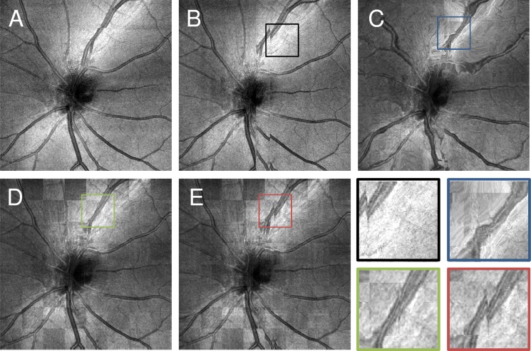
These results show that and or 1.0 both provide good registration results based on a similarity measure and also produce the most stable registration results when evaluating disjoint registrations of data from the same object. Because of space limitations the graphs showing similarity increase and stability for the individual imaging sessions are omitted. This data shows the same trend as the combined graphs and has similar optimal parameter settings. Figure 6 relates the graphs from Fig. 5 to the en face OCT fundus images for the different parameter settings. Figures 6(A) and 6(B) show OCT fundus images from the two input volumes used for this comparison. Figure 6(C) shows a checkerboard image of the two registered volumes using the volumes from Figs. 6(A) and 6(B) as input and also very low regularization strength of . A checkerboard image is constructed from two images, in this case the images from Figs. 6(A) and 6(B), where one image or the other is shown according to the block structure of a checkerboard. This display is a useful tool to assess the similarity of two images. The checkerboard shows almost no discontinuities, but the structure of the optic nerve head is severely distorted. In the graphs from Fig. 5, this corresponds to high similarity and low stability index for this setting. Figure 6(D) shows a checkerboard image, similar to C but with more adequate regularization strength of . Here, the structure remains undistorted and similarity is also high as the checkerboard image does not show discontinuities. Finally, Fig. 6(E) shows a checkerboard image with . The discontinuities that are visible in the vessel pattern indicate that the similarity after registration is low.
Fig. 6.
Visual depiction of registration performance in relation to alpha parameter. A: En face fundus projection of XFast input volume. B: En face fundus projection of YFast input volume. C: Checkerboard image between the en face fundus projections of the volumes from A and B registered with . D: Checkerboard image with the same inputs as C registered with. E: Checkerboard image with the same inputs as C and D registered with . Lower right: Zoomed views on areas indicated with rectangles in B to E.
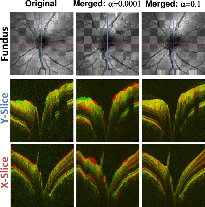
Figure 7 gives an impression of how well disjoint original volumes and registration results from disjoint input volume pairs agree after quasi-rigid registration. The variability of unprocessed input volumes can be seen in the left column. The middle and right columns show the variability of between two disjoint volume pairs after motion correcting each pair and subsequently quasi-rigidly registering the merged results. While the middle column shows considerable variability, the agreement between the volumes that were corrected with suitable parameters andis very good. These results are in agreement with the graphs from Fig. 5. When the value of α and/or is too low, the penalty on modeled motion is very low. Therefore, optimizing the objective function will primarily maximize similarity between the volumes with little regard for the time structure of the OCT scanning process. However, values that are too high will penalize deformation of the input volumes too much, so that the actual distortion that was caused by motion cannot be corrected, leading to low similarity after registration. With suitable α and however, both goals are reasonably balanced and high similarity as well as structural integrity can be achieved. For the following evaluation the parameters are set to the experimentally determined optimal values of and.
Fig. 7.
Structural variations before and after motion correction. Left column: Two original X-FAST input volumes quasi-rigidly registered. Middle column: Two disjoint volume pairs with the same X-FAST input volumes as used in the left column motion corrected and merged with and . The two merged volumes were then quasi rigidly registered and are shown. Right column: Same as middle column with . Top Row: Checkerboard fundus views of different quasi-rigidly registered volumes. Middle Row: Red-green composite images of the central slices in y direction. Bottom Row: Red-green composite images of the central slices in x direction. Both the original volumes and the volumes that were processed with a too low alpha show considerable variability in structure. In contrast, the volumes that were corrected with the optimal settings (right) show a very high degree of agreement.
3.3 Signal improvement
In addition to correcting artifacts caused by relative motion between the object and imaging device, the subsequent merging step of two or more registered volumes also improves signal-to-noise ratio (SNR) and image quality. Speckle noise tends to be de-correlated between A-scans from the same location in the multiple input volumes because of small variations in the position of microscopic structures imaged. In addition, movement of the subject can lead to an angle compounding effect, which will also de-correlate speckle. On a log scale, the speckle noise can be assumed to be zero mean additive noise [26]. If the registration is accurate, the true signal is correlated, while the noise components will tend average out by the merging process, which essentially calculates the mean of log intensity over corresponding voxels over all registered volumes. Merging multiple data sets is only possible when motion correction is excellent, because uncorrected motion would cause loss of image resolution. The high quality of the merged data is another indication of good algorithm performance.
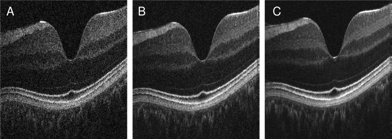
Figure 8 shows an example of image improvement obtained by merging. The three images show approximately the same retinal location at the fovea. The left image has the original signal level. By registering and merging two (middle) and six (right) volumes, signal level and image quality is improved. The background becomes more homogeneous and darker, while the retinal layers become easier to differentiate. Signal from the choroid is also increased. The signal to noise ratio (SNR) in these images is calculated using the formula
Fig. 8.
Cross sectional images from corresponding volumes showing signal and image quality improvement. A: Input cross sectional image along the fast direction of a volume from IS2. B: Corresponding image produced by registering and merging two volumes from IS2. C: Corresponding image from registering and merging six volumes from IS2.
| (8) |
where Ais the image in linear amplitude scale and σis the standard deviation in linear amplitude scale of a background region in the image [27]. The SNR for the original image in Fig. 8(A) is 49.5 dB, while in Fig. 8(B) where two volumes are merged the SNR increases to 56.5 dB. For six volumes merged (Fig. 8(C)), SNR increases to 62.5 dB. Overall, these results are in agreement with previous results from standard OCT averaging of multiple B-Scans from the same location [28]. SNR increases more than would be predicted when assuming a standard model. The SNR increase might be explained by the additional spatial smoothing that is applied when interpolating volumes to generate registered volumes.
3.4 Visual inspection
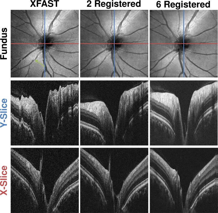
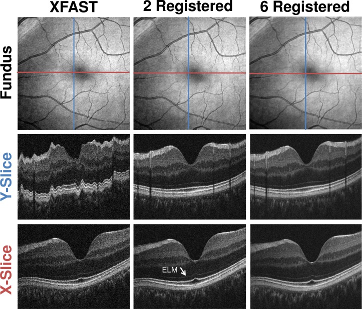
Visual inspection of the volumes before and after registration and merging is also used to assess algorithm performance. Figures. 9 and 10 show how the optic nerve head data sets of IS1 and the macular region data sets of IS2 are improved by registration and merging. Motion artifacts in the input volumes, such as the saccade in the fundus projection (Fig. 9 , top row, left column, green arrow) are corrected by registration and merging. Registration and merging improves the separation between background and retina, while the visibility of fine structures, such as the external limiting membrane (Fig. 10 , white arrow) is improved. Registering and merging more than two volumes increases signal quality further, while retaining fine structural details.
Fig. 9.
Comparison of Optic Nerve Head Volumes from IS1 before and after Registration and Merging. Top row: En face fundus projections. Second row: Single central slice in Y direction. (blue line in fundus) Third row: Single central slice in X direction. (red line in fundus) First column: XFAST input volume. Second column: Registered and merged result volume using as inputs the volumes of the first two columns. Third column: Registered and merged result volume using all six volumes from IS1 as input. Cross-sectional images are cropped axially.
Fig. 10.
Comparison of Macular Region Volumes from IS2 before and after Registration and Merging. Top row: En face fundus projections. Second row: Single central slice in Y direction. (blue line in fundus) Third row: Single central slice in X direction. (red line in fundus) First column: XFAST input volume. Second column: Registered and merged result volume using as inputs the volumes of the first two columns. Third column: Registered and merged result volume using all six volumes from IS2 as input. Cross-sectional images are cropped axially.
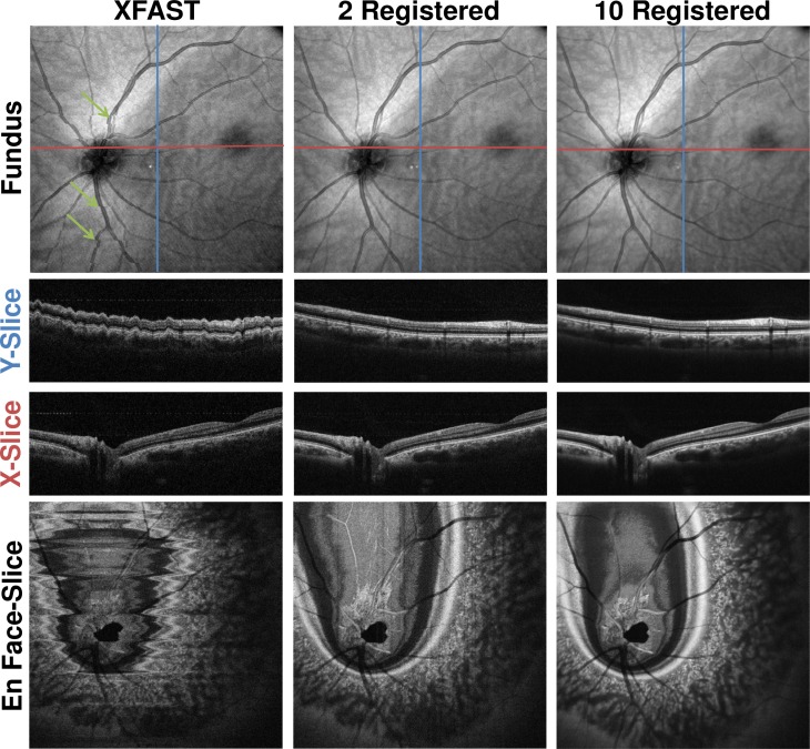
Figure 11 shows an example of the results of applying the algorithm to wide field OCT data from the IS3 imaging session using system B. The en face fundus projection of the XFAST input shows discontinuities caused by saccadic motion in the center of the volume (green arrows). In addition, the cross-sectional slices along the respective slow directions of the volumes show distortion in axial direction consistent with heartbeat and/or respiration. In the input volumes, motion distorts the retinal structure visible in both the en face and cross-sectional images. The results from processing two and ten volumes correct visible motion artifacts. Volume merging improves image quality and signal strength with respect to the background. This enhancement of SNR is already present in the two-volume case and increases when the number of volumes is increased. No visible loss of resolution occurs. For the ten volume case, the underlying optimization problem has over 36 million variables.
Fig. 11.
Comparison between 12 mm x 12 mm Data Sets from IS3 before and after registration and merging. Top row: En face fundus projections. Second row: Single central slice in Y direction. (blue line in fundus) Third row: Single central slice in X direction. (red line in fundus) Last row: Single central en face slice. First column: XFAST input volume. Second column: Registered and merged result volume using as inputs the volumes of the first two columns. Third column: Registered and merged result volume using all ten volumes from IS3 as input. Cross-sectional images are cropped axially to only show actual structure.
Together, these results show the algorithm corrects motion artifacts and improves signal quality in data sets which span multiple scales, independently of the object being imaged.
4. Summary and conclusion
This manuscript presents a software based OCT motion correction algorithm which can correct motion in three dimensions and on a per A-scan basis and enables merging motion corrected volume data to enhance the OCT signal quality without requiring a motion free reference image or additional hardware on the OCT instrument.
The algorithm estimates motion by iteratively optimizing a global objective function which captures two goals. First, after correction using an accurate motion estimate, the volumes should be similar to each other. Second, modeled motion within a short time scale is penalized. After optimization, the motion estimates are used to construct registered and motion corrected volumes. These volumes are then combined to a single merged volume using an adaptive weighted sum.
Experiments performed on OCT data from two different systems indicate that the algorithm can fully automatically perform motion correction in three dimensions on different scale data and independent of the subject imaged. Good registration results were obtained for different OCT systems and regions of the retina using a single set of algorithm parameter settings that was found using quantitative evaluation. Also, signal quality is enhanced through volume combination. In contrast to other motion correction approaches, no second imaging modality or additional hardware is required. Therefore, this method can be applied to a wide range of existing OCT systems without increasing cost and complexity.
Since registered merged volumes do not show motion artifacts and have improved image quality, the reproducibility of quantitative measurements from OCT volumetric data is expected to improve. Measurements such as nerve fiber layer (NFL) thickness are important for the diagnosis of glaucoma and assessing progression. Measurement of features such as retinal pigment epithelium elevation, drusen number and volume, hard exudate number and volume as well as other pathologies may be surrogate markers of disease progression. Improved reproducibility for quantitative measurement can lead to clinical advances in detection and tracking of retinal pathology. However, the proposed algorithm has limitations. In order to enable clinical use, execution speed and the robustness with low SNR input volumes needs to be optimized further. One limitation of the objective function is that it does not model different tilt or rotation of the head around the visual axis between the input volumes. Such effects will introduce artificial motion that has to be modeled in order to register the input volumes. This additional motion is penalized by regularization. In a worst-case scenario, the penalty that is induced by these effects may prevent good registration. In practice, severe misalignment of the input volumes with respect to the pupil position and head rotation around the optical axis should therefore be avoided by consistent alignment by the operator when using the algorithm.
The presence of floaters or severe and changing vignetting also violates the assumption of the algorithm that an A-scan that was acquired at a given position in tissue has only image information that depends on the tissue. Depending on the amount of these effects in the data volumes, registration algorithm performance may be impaired. In addition, the current algorithm requires isotropically sampled raster scan input volumes. Extending the algorithm to non-isotropically sampled orthogonal raster scans or non-raster scan patterns would also be important for some future applications. Finally, the current method operates on OCT intensity data. It is possible to extend the method to also register and merge functional OCT imaging data, such as Doppler and polarization sensitive OCT.
It is also expected that the algorithm has limitations on the ability to correct motion artifacts depending on the overall signal to noise of the volume as well as the frequency and magnitude of motion artifacts. The data presented in this paper has relatively good input signal quality and moderate amounts of motion. Because evaluating algorithm performance requires acquiring and registering large numbers of data sets, the evaluation in this manuscript was limited to data from a single healthy subject, but with data acquired from multiple instruments and scan protocols. These examples are a proof of concept. Further investigations on the algorithm performance with low signal and high motion data sets from patients with retinal pathologies are necessary.
In conclusion, we believe that registration can play an important role in improving clinical OCT data quality and measurement reproducibility. These advances will be particularly important for the assessment of diseases such as glaucoma, age related macular degeneration and diabetic retinopathy, which require precise and reproducible measurement to track disease progression.
Acknowledgments
This research is sponsored in part by the National Institutes of Health R01-EY011289-25, R01-EY013178-11, R01-EY013516-09, R01-EY019029-03, R01-HL095717-03, R01-NS057476-05, Air Force Office of Scientific Research FA9550-10-1-0063 and Medical Free Electron Laser Program FA9550-10-1-0551. The authors also gratefully acknowledge funding of the Erlangen Graduate School in Advanced Optical Technologies (SAOT) by the German Research Foundation (DFG) in the framework of the German excellence initiative. R. Bock, J. Hornegger, M. Kraus, M. Mayer and B. Potsaid receive royalties from intellectual property licensed to Optovue, Inc. J. Fujimoto receives royalties from intellectual property licensed to Carl Zeiss Meditec and Optovue, Inc. We thank Kenny Tao, Chao Zhou, Tsung-Han Tsai, Hsiang-Chieh Lee, Maria Polyanskaya and Eva Kollorz for valuable discussions and assistance.
References and links
- 1.Huang D., Swanson E. A., Lin C. P., Schuman J. S., Stinson W. G., Chang W., Hee M. R., Flotte T., Gregory K., Puliafito C. A., Fujimoto J. G., “Optical coherence tomography,” Science 254(5035), 1178–1181 (1991). 10.1126/science.1957169 [DOI] [PMC free article] [PubMed] [Google Scholar]
- 2.J. S. Schuman, C. A. Puliafito, and J. G. Fujimoto, Optical Coherence Tomography of Ocular Diseases, 2nd ed. (Slack, Thorofare, NJ, 2004). [Google Scholar]
- 3.Wojtkowski M., Leitgeb R., Kowalczyk A., Bajraszewski T., Fercher A. F., “In vivo human retinal imaging by Fourier domain optical coherence tomography,” J. Biomed. Opt. 7(3), 457–463 (2002). 10.1117/1.1482379 [DOI] [PubMed] [Google Scholar]
- 4.Fercher A. F., Hitzenberger C. K., Kamp G., Elzaiat S. Y., “Measurement of intraocular distances by backscattering spectral interferometry,” Opt. Commun. 117(1-2), 43–48 (1995). 10.1016/0030-4018(95)00119-S [DOI] [Google Scholar]
- 5.Häusler G., Linduer M. W., “‘Coherence radar’ and ‘spectral radar’—new tools for dermatological diagnosis,” J. Biomed. Opt. 3(1), 21–31 (1998). 10.1117/1.429899 [DOI] [PubMed] [Google Scholar]
- 6.Chinn S. R., Swanson E. A., Fujimoto J. G., “Optical coherence tomography using a frequency-tunable optical source,” Opt. Lett. 22(5), 340–342 (1997). 10.1364/OL.22.000340 [DOI] [PubMed] [Google Scholar]
- 7.Lexer F., Hitzenberger C. K., Fercher A. F., Kulhavy M., “Wavelength-tuning interferometry of intraocular distances,” Appl. Opt. 36(25), 6548–6553 (1997). 10.1364/AO.36.006548 [DOI] [PubMed] [Google Scholar]
- 8.Potsaid B., Gorczynska I., Srinivasan V. J., Chen Y. L., Jiang J., Cable A., Fujimoto J. G., “Ultrahigh speed spectral/Fourier domain OCT ophthalmic imaging at 70,000 to 312,500 axial scans per second,” Opt. Express 16(19), 15149–15169 (2008). 10.1364/OE.16.015149 [DOI] [PMC free article] [PubMed] [Google Scholar]
- 9.S. Ricco, M. Chen, H. Ishikawa, G. Wollstein, and J. Schuman, “Correcting motion artifacts in retinal spectral domain optical coherence tomography via image registration,” in Medical Image Computing and Computer-Assisted Intervention—MICCAI 2009 (Springer, 2009), pp. 100–107. [DOI] [PMC free article] [PubMed] [Google Scholar]
- 10.Robinson D. A., “Mechanics of human saccadic eye movement,” J. Physiol. 174(2), 245–264 (1964). [DOI] [PMC free article] [PubMed] [Google Scholar]
- 11.Kim J. S., Ishikawa H., Sung K. R., Xu J. A., Wollstein G., Bilonick R. A., Gabriele M. L., Kagemann L., Duker J. S., Fujimoto J. G., Schuman J. S., “Retinal nerve fibre layer thickness measurement reproducibility improved with spectral domain optical coherence tomography,” Br. J. Ophthalmol. 93(8), 1057–1063 (2009). 10.1136/bjo.2009.157875 [DOI] [PMC free article] [PubMed] [Google Scholar]
- 12.Swanson E. A., Izatt J. A., Hee M. R., Huang D., Lin C. P., Schuman J. S., Puliafito C. A., Fujimoto J. G., “In vivo retinal imaging by optical coherence tomography,” Opt. Lett. 18(21), 1864–1866 (1993). 10.1364/OL.18.001864 [DOI] [PubMed] [Google Scholar]
- 13.Zawadzki R. J., Fuller A. R., Choi S. S., Wiley D. F., Hamann B., Werner J. S., “Correction of motion artifacts and scanning beam distortions in 3D ophthalmic optical coherence tomography imaging,” Proc. SPIE 6426, 642607–, 642607-11. (2007). 10.1117/12.701524 [DOI] [Google Scholar]
- 14.Jørgensen T. M., Sander B., “Contrast enhancement of retinal B-scans from OCT3/Stratus by image registration—clinical application,” Proc. SPIE 6426, 642608–, 642608-7. (2007). 10.1117/12.699500 [DOI] [Google Scholar]
- 15.D. A. Tolliver, H. Ishikawa, J. S. Schuman, and G. L. Miller, “An in-painting method for combining multiple SD-OCT scans with applications to Z-motion recovery, noise reduction and longitudinal studies,” in ARVO 2009 Annual Meeting Abstracts (2009), Vol. 50, p. 1100. [Google Scholar]
- 16.Ferguson R. D., Hammer D. X., Paunescu L. A., Beaton S., Schuman J. S., “Tracking optical coherence tomography,” Opt. Lett. 29(18), 2139–2141 (2004). 10.1364/OL.29.002139 [DOI] [PMC free article] [PubMed] [Google Scholar]
- 17.Hammer D. X., Ferguson R. D., Magill J. C., Paunescu L. A., Beaton S., Ishikawa H., Wollstein G., Schuman J. S., “Active retinal tracker for clinical optical coherence tomography systems,” J. Biomed. Opt. 10(2), 024038 (2005). 10.1117/1.1896967 [DOI] [PMC free article] [PubMed] [Google Scholar]
- 18.Považay B., Hofer B., Torti C., Hermann B., Tumlinson A. R., Esmaeelpour M., Egan C. A., Bird A. C., Drexler W., “Impact of enhanced resolution, speed and penetration on three-dimensional retinal optical coherence tomography,” Opt. Express 17(5), 4134–4150 (2009). 10.1364/OE.17.004134 [DOI] [PubMed] [Google Scholar]
- 19.I. J. Schoenberg, Cardinal Spline Interpolation, Regional Conference Series In Applied Mathematics (Society for Industrial and Applied Mathematics, Philadelphia, 1973). [Google Scholar]
- 20.Thévenaz P., Ruttimann U. E., Unser M., “A pyramid approach to subpixel registration based on intensity,” IEEE Trans. Image Process. 7(1), 27–41 (1998). 10.1109/83.650848 [DOI] [PubMed] [Google Scholar]
- 21.J. Nocedal and S. J. Wright, Numerical Optimization, 2nd ed., Springer Series in Operations Research (Springer, New York, 2006). [Google Scholar]
- 22.Adelson E. H., Anderson C. H., Bergen J. R., Burt P. J., Ogden J. M., “Pyramid methods in image processing,” RCA Eng. 29, 33–41 (1984). [Google Scholar]
- 23.Fletcher R., “A new approach to variable metric algorithms,” Comput. J. 13(3), 317–322 (1970). 10.1093/comjnl/13.3.317 [DOI] [Google Scholar]
- 24.Potsaid B., Baumann B., Huang D., Barry S., Cable A. E., Schuman J. S., Duker J. S., Fujimoto J. G., “Ultrahigh speed 1050nm swept source/Fourier domain OCT retinal and anterior segment imaging at 100,000 to 400,000 axial scans per second,” Opt. Express 18(19), 20029–20048 (2010). 10.1364/OE.18.020029 [DOI] [PMC free article] [PubMed] [Google Scholar]
- 25.Maes F., Collignon A., Vandermeulen D., Marchal G., Suetens P., “Multimodality image registration by maximization of mutual information,” IEEE Trans. Med. Imaging 16(2), 187–198 (1997). 10.1109/42.563664 [DOI] [PubMed] [Google Scholar]
- 26.Schmitt J. M., Xiang S. H., Yung K. M., “Speckle in optical coherence tomography,” J. Biomed. Opt. 4(1), 95–105 (1999). 10.1117/1.429925 [DOI] [PubMed] [Google Scholar]
- 27.Wong A., Mishra A., Bizheva K., Clausi D. A., “General Bayesian estimation for speckle noise reduction in optical coherence tomography retinal imagery,” Opt. Express 18(8), 8338–8352 (2010). 10.1364/OE.18.008338 [DOI] [PubMed] [Google Scholar]
- 28.Sander B., Larsen M., Thrane L., Hougaard J. L., Jørgensen T. M., “Enhanced optical coherence tomography imaging by multiple scan averaging,” Br. J. Ophthalmol. 89(2), 207–212 (2005). 10.1136/bjo.2004.045989 [DOI] [PMC free article] [PubMed] [Google Scholar]


