Abstract
Purpose: Inverse planned intensity modulated radiation therapy (IMRT) has helped many centers implement highly conformal treatment planning with beamlet-based techniques. The many comparisons between IMRT and 3D conformal (3DCRT) plans, however, have been limited because most 3DCRT plans are forward-planned while IMRT plans utilize inverse planning, meaning both optimization and delivery techniques are different. This work avoids that problem by comparing 3D plans generated with a unique inverse planning method for 3DCRT called inverse-optimized 3D (IO-3D) conformal planning. Since IO-3D and the beamlet IMRT to which it is compared use the same optimization techniques, cost functions, and plan evaluation tools, direct comparisons between IMRT and simple, optimized IO-3D plans are possible. Though IO-3D has some similarity to direct aperture optimization (DAO), since it directly optimizes the apertures used, IO-3D is specifically designed for 3DCRT fields (i.e., 1–2 apertures per beam) rather than starting with IMRT-like modulation and then optimizing aperture shapes. The two algorithms are very different in design, implementation, and use. The goals of this work include using IO-3D to evaluate how close simple but optimized IO-3D plans come to nonconstrained beamlet IMRT, showing that optimization, rather than modulation, may be the most important aspect of IMRT (for some sites).
Methods: The IO-3D dose calculation and optimization functionality is integrated in the in-house 3D planning/optimization system. New features include random point dose calculation distributions, costlet and cost function capabilities, fast dose volume histogram (DVH) and plan evaluation tools, optimization search strategies designed for IO-3D, and an improved, reimplemented edge/octree calculation algorithm. The IO-3D optimization, in distinction to DAO, is designed to optimize 3D conformal plans (one to two segments per beam) and optimizes MLC segment shapes and weights with various user-controllable search strategies which optimize plans without beamlet or pencil beam approximations. IO-3D allows comparisons of beamlet, multisegment, and conformal plans optimized using the same cost functions, dose points, and plan evaluation metrics, so quantitative comparisons are straightforward. Here, comparisons of IO-3D and beamlet IMRT techniques are presented for breast, brain, liver, and lung plans.
Results: IO-3D achieves high quality results comparable to beamlet IMRT, for many situations. Though the IO-3D plans have many fewer degrees of freedom for the optimization, this work finds that IO-3D plans with only one to two segments per beam are dosimetrically equivalent (or nearly so) to the beamlet IMRT plans, for several sites. IO-3D also reduces plan complexity significantly. Here, monitor units per fraction (MU/Fx) for IO-3D plans were 22%–68% less than that for the 1 cm × 1 cm beamlet IMRT plans and 72%–84% than the 0.5 cm × 0.5 cm beamlet IMRT plans.
Conclusions: The unique IO-3D algorithm illustrates that inverse planning can achieve high quality 3D conformal plans equivalent (or nearly so) to unconstrained beamlet IMRT plans, for many sites. IO-3D thus provides the potential to optimize flat or few-segment 3DCRT plans, creating less complex optimized plans which are efficient and simple to deliver. The less complex IO-3D plans have operational advantages for scenarios including adaptive replanning, cases with interfraction and intrafraction motion, and pediatric patients.
Keywords: IMRT, optimization, SMLC, aperture, 3D
INTRODUCTION
The combination of inverse planning and beamlet-based intensity modulated radiation therapy (IMRT) delivery has led to the broad availability of highly conformal therapy in many institutions. Modern IMRT planning and delivery, however, routinely require large amounts of effort for both commissioning and daily use, including patient plan-specific QA.1 IMRT treatment delivery [for static (SMLC), dynamic (DMLC), tomotherapy, or other IMRT delivery techniques] makes use of sophisticated hardware and software and is often time consuming as well as complex. Highly complex IMRT treatment deliveries have been involved in some recent treatment misadministrations which have focused new attention on complexity in radiotherapy planning and delivery.1, 2, 3
In an attempt to study whether the highly conformal dose distributions obtained with IMRT can also be created with simpler 3D conformal (3DCRT) plans, the inverse-optimized 3D (IO-3D) conformal planning method described here applies the advantages of inverse planning to simple, flat 3DCRT fields, or fields which include a very small number (one or two) of additional segments in one or more fields. This work uses comparisons of these simple but optimized IO-3D plans versus those optimized with beamlet IMRT to illustrate both the similarities and differences between the dose distributions which are achievable with the two methods.
It is important to note that the IO-3D method is quite different from the previously published direct aperture optimization (DAO) methods.4, 5, 6, 7 Most published DAO methods begin the optimization process using a beamlet description of the beam and perform a beamlet optimization for a number of iterations. The algorithm then chooses candidate apertures after sequencing the intensity distributions and performs further optimization on this relatively large number of apertures (typically at least 5–10 per field). Most DAO methods are used to directly produce SMLC IMRT plans which fall under the same intensive QA requirements as plans generated using fluence optimization followed by leaf sequencing, although there have been a few studies which have studied DAO plans with the number of allowed segments per beam direction limited to very few segments per beam direction.5 In distinction to DAO, the IO-3D method has been designed to optimize simple 3DCRT plans and those with a very limited number of additional segments. IO-3D directly optimizes the shapes and weights of segments originally created by the planner, without any use of beamlet-based fluence optimization or dose calculation, or a need for more than one shape per beam direction. IO-3D can thus be applied to any conformal plan, even those with just two or three flat fields.
In the current work, quantitative comparisons of clinically derived IO-3D plans and optimized beamlet IMRT plans are shown for a number of clinical treatment sites, including breast, brain, liver, and lung. The same beam directions, clinical goals, cost functions, evaluation criteria, and plan metrics are used for the plans, and all analyses are performed in an identical manner to make the comparisons as quantitative as possible. This work studies only IO-3D plans with one to three segments per field and does not address more complex aperture based IMRT plans which can be designed using more segments per field or complex clinical sites (e.g., head/neck) which have multiple complex target volumes and many different normal tissues involved.
MATERIALS AND METHODS
Optimization system
All planning in this study has been performed using the in-house developed 3D planning and optimization system, UMPlan/UMOpt.8, 9, 10, 11 The basic characteristics of this system have been previously described. The current version consists of software developed in FORTRAN, C, and C++, and makes use of GKS and OpenGL for graphics, as well as a special version of AVS.10 The system runs on HP Alpha workstations, uses PCs with X-windows, and uses both OpenVMS alpha servers and a large Linux Parallel Cluster as calculation servers.
IO-3D conformal planning
3DCRT and few-segment plans in this work have been optimized using the IO-3D conformal planning algorithm originally described in 2000.12 IO-3D uses random downhill search strategies to optimize the shape and weight of all segments in a 3D or multisegment plan. The algorithm is based on use of a perturbational implementation of an improved version of the edge/octree dose calculation model13, 14 which allows for fast calculation of the complete 3D dose distribution change due to a change in beam weight or collimation (e.g., moving a single MLC leaf). The algorithm is used to optimize the shapes and weights of all segments originally defined for the given plan using search methods designed to address the difficult search space associated with few-segment plans. In this work, we do not investigate the creation of segments by the optimization algorithm, though segments which were changed to zero weight by the optimization were removed from further consideration for speed reasons. The IO-3D algorithm uses the same points, the same plan and metric evaluation methods, and the same “costlet-based” objective function methods (described by Kessler et al.11) as the beamlet-based optimizations.
Although this work bears a superficial similarity to published DAO methods,4, 5, 6, 7 the IO-3D algorithm is in fact quite different, as summarized in Table TABLE I.. From the overall goal of the algorithm (optimized 3DCRT rather than efficient IMRT) to the details of the search algorithms, the DAO and IO-3D algorithms have very different characteristics. The IO-3D algorithm does not start with a fluence and beamlet-based optimization to generate the multiple initial segments for the optimization like DAO. Rather, this algorithm begins with the routine calculation of the dose distribution for each field, where each field can consist of one or more MLC segment shapes (and weights). Typically, the initial segment shapes are defined by simple beam’s eye view conformation of the field shape to the target shape. If desired, one or more additional segment shapes per beam angle can be created: typically these segment shapes would be determined geometrically by excluding important normal tissues which overlap the target projections of the initial segments15 or by adding a segment or two to address target dose nonuniformity.16 After the initial dose calculation for each segment is performed, the IO-3D algorithm begins its search. Using one of a number of search strategies, a single MLC leaf is chosen for a move and then moved by a step size determined by the search strategy and/or user-defined parameter (step sizes can vary down to 1 mm). The perturbation to the dose distribution for this one change is calculated and added into the current dose, and then a short optimization is run considering changes in all the segment weights. The search strategy then decides whether to accept the leaf motion plus the optimal segment weightings found in the (inner loop) weight optimization, followed by moving on to the next step in the MLC leaf search strategy. The “inner” loop which finds the best segment weights each time an MLC leaf is moved is crucial, as it allows the optimization to progress toward high quality solutions in an incremental way, just as small beamlet weight changes do in a typical IMRT optimization.
TABLE I.
Differences between IO-3D and DAO methods.
| Method | IO-3D | DAO |
|---|---|---|
| Plan type used for initial setup | 3D CRT | IMRT (beamlets) |
| Segment creation | Defined by planner | Created by algorithm by sequencing beamlet IMRT plan |
| No. of segments typically used | 1 or 2 per beam direction | 5–20 (Refs. 4, 5, 6, 7) |
| Search resolution | Minimum step sizes set by user, as small as 1 mm leaf changes possible | Typically defined by beamlet sizes used for pencil beam corrections to segment dose calculation |
| Search strategy | Multilevel search: the inner loop of the search optimizes all the segment weights as part of each proposed MLC leaf change | Beamlet-type additions or removal from shapes, followed at end by segment weight optimization |
| Segments used | Starts with number defined by planner, reduces if possible | Number defined by various algorithm parameters, including minimum segment size, maximum number allowed, etc. |
| Overall goal | Simplest conformal plan which satisfies optimization criteria | More efficiently delivered IMRT plan |
Several different search strategies are available within the IO-3D optimization system to allow the user versatility when optimizing different types of cases. Two ordered search strategies are available—“Ordered” and “Ordered-Push”—which attempt to move each leaf by the defined step size while picking the next leaf in an ordered fashion, moving around each beam. The Ordered search strategy is capable of moving each leaf once per iteration, while the Ordered-Push can move each leaf as far as the cost function will allow for each iteration. In addition, two random search strategies are also available: “Random” and “RandomBeam + MLC.” Random attempts to move randomly chosen MLC leaves for a given number of iterations for each beam. The RandomBeam + MLC search strategy, however, will choose a random MLC leaf within a random beam for each iteration, so it searches in all fields concurrently. Qualitative observations have shown that the ordered search around all the leaves of each MLC segment typically results in smoother segment shapes, while the random search methods may result in more complex shapes. The jaw positions can also be included in the search strategies but this is often of little importance. The one exception is for small SRS or SBRT MLC-shaped fields, as 1 or 2 mm changes in the jaw positions at the top and bottom of the MLC apertures can be very important to the overall conformality of an SBRT plan.
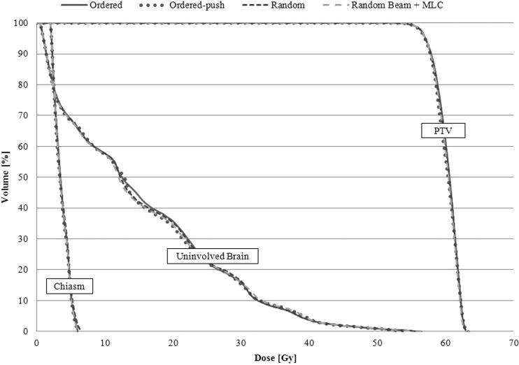
In order to show that the effect of the chosen search strategy on the dosimetric outcome of the plan is typically negligible, a simple six-field, noncoplanar brain case was optimized four separate times using the previously mentioned search strategies. For each optimization, the same starting MLC positions and beam weights, the same cost function, and the same step size and iteration parameters were used. The dose volume histogram (DVH) results shown in Fig. 1 show that all search methods are capable of producing dosimetrically similar plans. For the purposes of this study, the RandomBeam + MLC search was employed followed by the Ordered-Push search strategy to promote smoother aperture shapes at the end of optimization.
Figure 1.
DVHs showing the results achieved by using the four main search strategies in the IO-3D system.
Beamlet-based optimization
The beamlet-based IMRT planning used here makes use of the standard in-house IMRT planning methods within the UMOpt inverse planning/optimization system. Dose for the beamlet IMRT plans (created with 0.5 × 0.5 or 1 × 1 cm2 beamlets) is calculated with a convolution/superposition dose calculation algorithm derived from the work of Mackie et al.,17 using energy spectrums and other corrections derived from the BeamNRC Monte Carlo code modeling the accelerator. Various search algorithms for the beamlet intensities are implemented, but for this work, only a quasi-Newton gradient method is used. All objective functions for the optimization use the costlet functionality described by Kessler et al.11 Since the beamlet IMRT plans are intended to demonstrate the optimal result that can be achieved with IMRT, the MLC sequencing is performed with a large number of segments (typically up to 100 per beam) so that the deliverable IMRT plan achieves intensities with very little degradation due to the sequencing step (note: this is also our clinical practice). As has been shown in a number of papers, modulation and the number of MUs in the field are controlled using a number of different methods, including limiting the maximum beamlet intensity,18 penalizing high modulation changes,19 and through use of adaptive diffusion smoothing.20
Plans, plan comparison, and evaluation
All anatomical descriptions used here were based on CT scan sets previously obtained for radiotherapy treatment planning at our institution, but the plans were newly created for the current work under an IRB-approved protocol. All target and normal structure definitions were based on the segmentations performed for the patient’s clinical treatment, though minor modifications to the contours were made for consistency in the current study, if necessary.
A total of eight comparisons were performed, with two cases each for four different sites—breast, brain, liver, and lung. Plans were optimized using IO-3D and beamlet IMRT, with beamlet sizes chosen based on current local clinical practice. The cost functions for the optimization were based on local clinical practice and were tuned to meet the planning objectives shown in Table TABLE II.. In addition to the goals listed in Table TABLE II., lower priority objectives were also included to minimize dose to all organs and normal tissues. For all cases, the chosen beam angles were derived from the clinically treated beam angles. IO-3D and beamlet IMRT plans were optimized using identical cost functions and costlet weighting factors for each site.
TABLE II.
Planning objectives for breast, brain, liver, and lung cases.
| Structure | Objectives |
|---|---|
| Partial breast inverse plan objectives | |
| PTV | 40 Gy ± 5% |
| Heart | <1% ≥ 3 Gy |
| Lung | <10% ≥ 5 Gy |
| Ipsilateral breast | Minimize dose |
| Contralateral breast | <1% ≥ 5 Gy |
| Whole breast inverse planning objectives | |
| PTV | 50 Gy ± 5% |
| Heart | Max ≤ 15 Gy |
| Ipsilateral lung | <33% ≤ 18 Gy |
| Brain inverse planning objectives | |
| PTV1 | 60 Gy ± 5% |
| PTV2 | 46 Gy ± 5% |
| Chiasm | Max ≤ 54 Gy |
| Eyes | Max ≤ 45 Gy |
| Optic nerves | Max ≤ 54 Gy |
| Brain-PTV2 | Minimize dose |
| Liver inverse plan objectives | |
| PTV | 90 Gy ± 5% |
| Liver | NTCP ≤ 10% |
| Kidneys | Max ≤ 18 Gy (if cannot reach this for both kidneys, spare one) |
| Cord | Max ≤ 50 Gy |
| Stomach | Max ≤ 55 Gy |
| Heart | Minimize dose |
| Esophagus | Max ≤ 78 Gy |
| Duodenum | Max ≤ 55 Gy |
| Lung inverse planning objectives | |
| PTV | 72 Gy ± 5%, minimum of 63 Gy |
| Cord | Max ≤ 50 Gy |
| Esophagus | Max ≤ 78 Gy, NTCP ≤ 47% |
| Heart | Max ≤ 40 Gy, NTCP ≤ 5% |
| Lungs-GTV | NTCP ≤ 17.2% |
Note: All normal structure doses were minimized after the listed planning objectives were met.
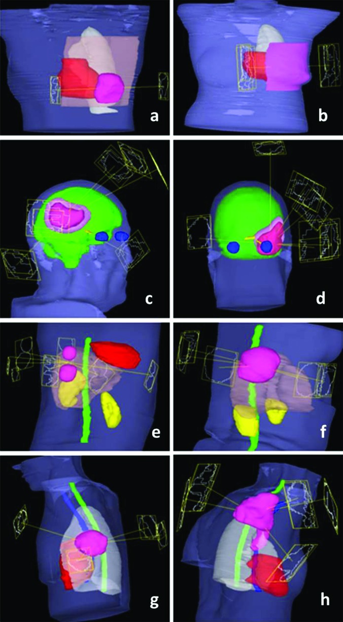
Plans were performed with 6 and 16X beams from a Varian 21EX accelerator equipped with standard 120 leaf MLC (0.5 and 1.0 cm width leaves). Beamlet optimization for most plans was performed using 1 cm × 1 cm beamlets, with the exception of brain plan comparisons which include both 1 cm × 1 cm and 0.5 cm × 0.5 cm beamlet IMRT plans. For some IO-3D cases, additional segments (one or at most two per beam angle) were added to existing beam angles to allow small to moderate levels of modulation in the optimized 3DCRT plans, if the optimization found it useful. The geometries for each case are presented in Fig. 2.
Figure 2.
Case geometries and beam angles: (a) and (b) Breast cases with PTVs shown in pink, heart in red, and normal breast (for PBI case) in brown. (c) and (d) Brain cases with innermost PTVs (PTV1) shown in dark pink, outermost PTVs (PTV2) in light pink, normal brain in green, eyes in blue, and optic nerves and chiasm in yellow. (e) and (f) Liver cases with PTVs shown in pink, cord in green, kidneys in yellow, heart in red, and normal liver in brown. (g) and (h) Lung cases with PTVs shown in pink, heart in red, cord in green, esophagus in blue, and normal lung in white.
Each case was optimized with IO-3D and beamlet IMRT plans and then compared quantitatively and qualitatively using a number of metrics including DVHs, structure mean doses, a maximum dose metric, and the dose to 99% of the PTV volume (D99). The metric for the maximum dose values to each structure is not the max dose to a point, rather it specifies the dose for the hottest 0.1 cc (for optic structures) or 0.5 cc (for other structures), a metric which is much less sensitive to sampling and resolution uncertainties. Furthermore, the outputs for NTCP limits used to constrain specific structure doses within the optimization are compared, along with the monitor units per fraction (MU/Fx) and the number of segments in each plan.
RESULTS
Breast cases
Partial breast case
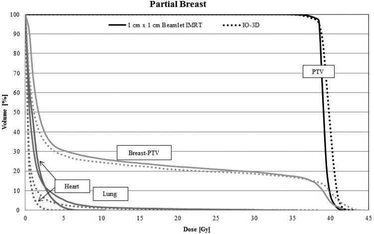
The original IO-3D tangential field plan for the partial breast case was defined with four segments (two segments per beam angle), none of which were eliminated by the IO-3D optimization. As shown by the final DVHs in Fig. 3, the PTV and uninvolved breast tissue doses produced by the optimized IO-3D plan have slightly higher dose tails than the IMRT plan (note that this is allowed by the cost function). However, the low doses to the heart and the lung were reduced in the IO-3D plan.
Figure 3.
DVHs for the four segment IO-3D plan (two segments per beam direction) and the 1 cm × 1 cm beamlet IMRT plan. DVHs are shown for the partial breast PTV, normal breast (breast-PTV) (green), ipsilateral lung (blue), and the heart (red).
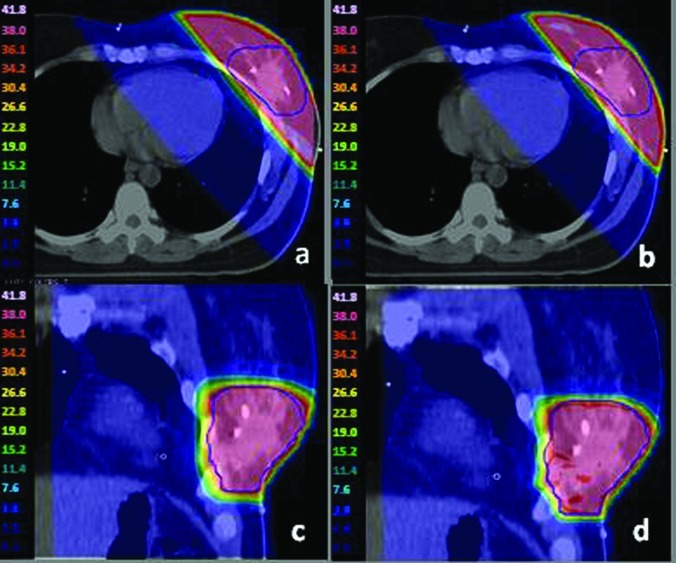
While the two plans are dosimetrically similar, the delivery efficiency of the IO-3D plan is superior. As seen in Table TABLE III., the IMRT plan required 143 segments with 369 MU/Fx, whereas the IO-3D plan had only four segments and could be delivered with 173 MU/Fx. The IO-3D and IMRT dose distributions (Fig. 4) are very similar.
TABLE III.
Dose results and delivery efficiency for partial breast and whole breast cases.
| Mean dose (Gy) | Maximum dosea (Gy) | PTV D99 (Gy) | Delivery efficiency | ||||||
|---|---|---|---|---|---|---|---|---|---|
| Structure | 1 × 1 IMRT | IO-3D | 1 × 1 IMRT | IO-3D | 1 × 1 IMRT | IO-3D | 1 × 1 IMRT | IO-3D | |
| Partial breast | |||||||||
| PTV | 39.2 | 39.8 | 41.4 | 42.0 | 37.4 | 36.8 | MU/Fx | 369 | 173 |
| Heart | 1.1 | 0.4 | 6.9 | 3.7 | — | — | Segments | 143 | 4 |
| Lung | 1.3 | 0.8 | 33.3 | 36.5 | — | — | Delivery time estimate (min) | 1.5 | 0.4 |
| Whole breast | |||||||||
| PTV | 50.5 | 49.9 | 53.0 | 53.9 | 47.0 | 46.9 | MU/Fx | 305 | 239 |
| Heart | 1.4 | 1.7 | 34.5 | 30.5 | — | — | Segments | 113 | 6 |
| Lung | 2.0 | 2.4 | 37.6 | 39.3 | — | — | Delivery time estimate (min) | 2.0 | 0.4 |
Maximum doses to 0.50 cc.
Figure 4.
For the whole breast case, (a) and (c) 1 cm × 1 cm IMRT plan dose color wash; (b) and (d) IO-3D plan dose color wash.
Whole breast case
For the whole breast case, the IO-3D plan contained six segments in two beam angles, all of which were utilized. The mean doses to the heart and ipsilateral lung were similar for both techniques. While the maximum dose to the lung was higher with IO-3D, the maximum dose to the heart was lower by 4 Gy for the IO-3D plan. Similar to the results for the partial breast case, the IO-3D plan had fewer MU/Fx and a significant reduction in the number of segments (see Table TABLE III.).
Brain cases
Brain 1
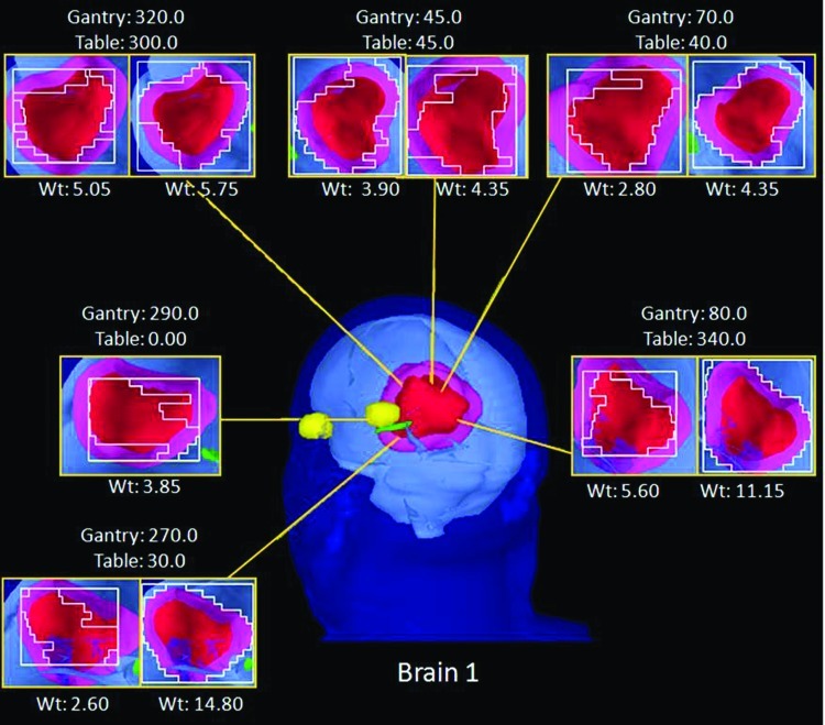
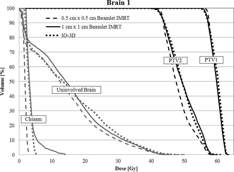
The original IO-3D plan for brain 1 was initially defined with 6 noncoplanar beam directions and 12 segments (two segments per beam angle). One segment was ultimately eliminated by the IO-3D optimization (final segments shown in Fig. 5). The DVHs in Fig. 6 show that the 0.5 cm × 0.5 cm beamlet IMRT plan achieved the best dosimetric results by maximizing PTV1 homogeneity, minimizing the maximum dose to PTV2 and reducing the dose to the uninvolved brain tissue and chiasm better than the other two optimizations. The IO-3D plan achieved results that were more favorable than the 1 cm × 1 cm beamlet IMRT plan by achieving a similar PTV homogeneity while reducing the doses for the normal structures significantly. The 0.5 cm × 0.5 cm beamlet IMRT plan required 528 segments and 932 MU/Fx, and the 1 cm × 1 cm beamlet IMRT plan used 193 segments and 386 MU/Fx, while the IO-3D plan required only 11 segments and 268 MU/Fx to achieve the results shown in Fig. 6 and Table TABLE IV.. The maximum and mean doses to the left and right eyes for all three plans were less than 1 Gy and are, therefore, not included in the DVH comparison.
Figure 5.
BEV displays for each segment of the IO-3D Plan for brain 1.
Figure 6.
DVHs are shown for the brain 1 case for the three optimized plans (0.5 cm × 0.5 cm IMRT, 1 cm × 1 cm IMRT, and IO-3D) for PTV1, PTV2, uninvolved brain (brain-PTV2), and the optic chiasm.
TABLE IV.
Dose results and delivery efficiency for brain 1 and brain 2.
| Mean dose (Gy) | Maximum dosea (Gy) | PTV D99 (Gy) | Delivery efficiency | ||||||||||
|---|---|---|---|---|---|---|---|---|---|---|---|---|---|
| Structure | 0.5 × 0.5 IMRT | 1 × 1 IMRT | IO-3D | 0.5 × 0.5 IMRT | 1 × 1 IMRT | IO-3D | 0.5 × 0.5 IMRT | 1 × 1 IMRT | IO-3D | 0.5 × 0.5 IMRT | 1 × 1 IMRT | IO-3D | |
| Brain 1 | |||||||||||||
| PTV1 | 59.7 | 59.6 | 59.9 | 62.7 | 62.8 | 62.9 | 55.6 | 56.0 | 55.6 | MU/Fx | 932 | 386 | 268 |
| PTV2 | 48.2 | 49.6 | 49.5 | 57.6 | 58.3 | 58.7 | 42.5 | 41.8 | 41.6 | Segments | 528 | 193 | 11 |
| Chiasm | 1.8 | 3.6 | 3.0 | 2.4 | 5.4 | 4.3 | — | — | — | Delivery time estimate (min) | 5.1 | 2.5 | 0.4 |
| R eye | 0.3 | 0.4 | 0.4 | 0.5 | 0.9 | 0.5 | — | — | — | ||||
| L eye | 0.3 | 0.4 | 0.4 | 0.5 | 0.8 | 0.5 | — | — | — | ||||
| Uninvolved brain | 13.6 | 15.0 | 15.1 | 48.0 | 45.1 | 48.5 | — | — | — | ||||
| Brain 2 | |||||||||||||
| PTV1 | 59.6 | 59.5 | 59.4 | 62.9 | 62.9 | 64.3 | 56.1 | 55.0 | 55.0 | MU/Fx | 1004 | 494 | 162 |
| PTV2 | 49.0 | 50.3 | 50.5 | 57.7 | 58.5 | 59.2 | 42.5 | 41.9 | 40.4 | Segments | 426 | 184 | 10 |
| Chiasm | 16.6 | 23.8 | 20.4 | 46.1 | 48.1 | 45.7 | — | — | — | Delivery time estimate (min) | 4.1 | 2.33 | 0.4 |
| R eye | 0.5 | 0.8 | 0.5 | 1.0 | 1.5 | 1.0 | — | — | — | ||||
| L eye | 1.3 | 1.9 | 5.0 | 5.3 | 8.3 | 16.2 | — | — | — | ||||
| L optic N | 20.5 | 26.0 | 24.0 | 45.4 | 49.1 | 47.6 | — | — | — | ||||
| Uninvolved brain | 9.1 | 10.0 | 13.0 | 62.0 | 63.0 | 64.5 | — | — | — | ||||
Maximum doses to 0.10 cc for optic structures and 0.50 cc for all other structures.
Brain 2
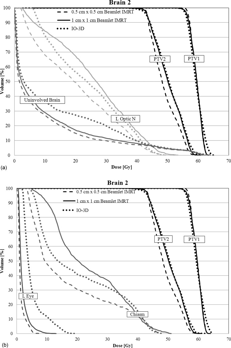
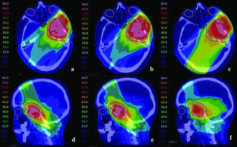
For brain 2, the IO-3D plan made use of six beam angles with two segments per angle, two of which were eliminated during the optimization. The 0.5 cm × 0.5 cm beamlet IMRT plan showed improved dosimetric plan quality over the 1 cm × 1 cm beamlet IMRT plan and the IO-3D plan with increased PTV homogeneity, as seen in Figs. 78. Due to the close proximity of the PTVs to the optic structures, the number of degrees of freedom in the 1 cm × 1 cm beamlet IMRT plan and the IO-3D plan were likely not sufficient to reduce the doses of the OARs to the same level reached by the 0.5 cm × 0.5 cm beamlet IMRT plan. However, none of the plans violate the planning objectives in Table TABLE II.. Additionally, the IO-3D plan is capable of significantly reducing plan complexity as shown in Table TABLE IV..
Figure 7.
DVHs for case brain 2 are shown for the three optimized plans (0.5 cm × 0.5 cm IMRT, 1 cm × 1 cm IMRT, and IO-3D) for PTV1, PTV2, uninvolved brain (brain-PTV2), optic chiasm, left optic nerve, and the left eye.
Figure 8.
For case brain 2, PTV1 (dashed blue) and PTV2 (solid blue) are shown for (a) and (d) 0.5 cm × 0.5 cm IMRT plan, (b) and (e) 1 cm × 1 cm IMRT plan, and (c) and (f) IO-3D plan.
Liver cases
Liver 1
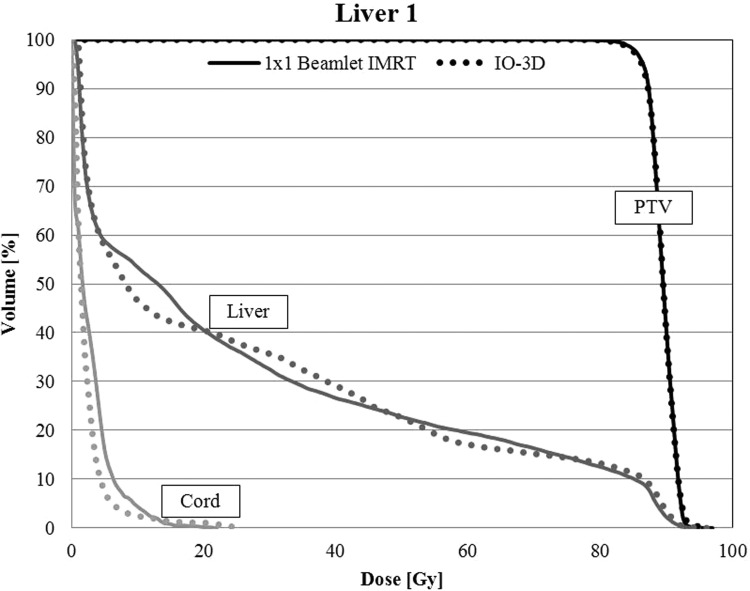
The original IO-3D plan for liver 1 was planned and optimized with seven segments, one per beam angle, and none of the original segments were eliminated by the IO-3D optimization. The IO-3D plan was able to reduce the mean doses below that of the IMRT plan for the liver, cord, kidney, stomach, heart, and esophagus for liver 1 (Table TABLE V.). Additionally, the NTCPs for the liver were comparable between the beamlet IMRT plan and the IO-3D plan with values of 10.3% and 10.1%, respectively. The IMRT plan required 477 MU/Fx and 307 segments while the IO-3D plan required only 287 MU/Fx and seven segments. Maximum and mean doses to all other structures used to constrain the optimization (left kidney, esophagus, heart, stomach, and duodenum) were all below 10 Gy. The DVHs for beamlet and IO-3D plans are shown in Fig. 9.
TABLE V.
Dose results and delivery efficiency for liver 1 and liver 2.
| Mean dose (Gy) | Maximum dosea (Gy) | NTCP (%) | PTV D99 (Gy) | Delivery efficiency | |||||||
|---|---|---|---|---|---|---|---|---|---|---|---|
| Structure | 1 × 1 IMRT | IO-3D | 1 × 1 IMRT | IO-3D | 1 × 1 IMRT | IO-3D | 1 × 1 IMRT | IO-3D | 1 × 1 IMRT | IO-3D | |
| Liver 1 | |||||||||||
| PTV | 90.0 | 90.1 | 92.8 | 93.5 | — | — | 86.9 | 86.3 | MU/Fx | 477 | 287 |
| Liver | 34.3 | 34.0 | 92.7 | 93.5 | 10.3 | 10.1 | — | — | Segments | 307 | 7 |
| Cord | 2.0 | 1.5 | 8.9 | 4.9 | — | — | — | — | Delivery time estimate (min) | 3.5 | 0.5 |
| R Kidney | 6.4 | 4.6 | 34.7 | 35.5 | — | — | — | — | |||
| L Kidney | 0.2 | 0.4 | 1.0 | 1.0 | — | — | — | — | |||
| Stomach | 2.1 | 1.6 | 7.6 | 9.0 | — | — | — | — | |||
| Heart | 1.7 | 1.1 | 9.6 | 8.3 | — | — | — | — | |||
| Esophagus | 3.2 | 1.5 | 5.3 | 2.5 | — | — | — | — | |||
| Duodenum | 2.6 | 2.3 | 0.6 | 3.8 | — | — | — | — | |||
| Liver 2 | |||||||||||
| PTV | 89.5 | 89.5 | 94.5 | 95.8 | — | — | 83.9 | 83.4 | MU/Fx | 632 | 284 |
| Liver | 26.6 | 26.3 | 94.3 | 95.8 | 0.30 | 0.20 | — | — | Segments | 326 | 6 |
| Cord | 2.7 | 2.3 | 18.3 | 23.8 | — | — | — | — | Delivery time estimate (min) | 4.1 | 0.5 |
| R Kidney | 0.2 | 0.9 | 1.1 | 1.5 | — | — | — | — | |||
| L Kidney | 0.4 | 0.8 | 1.4 | 1.5 | — | — | — | — | |||
Maximum doses to 0.50 cc.
Figure 9.
For liver 1, DVHs for the PTV, uninvolved liver (liver-GTV), and the spinal cord are shown for the 1 cm × 1 cm IMRT and IO-3D optimized plans.
Liver 2
For the liver 2 case, six beams were used, with one segment per beam angle for the IO-3D plan. No segments were eliminated from the optimization in the IO-3D plan. The PTV homogeneity objective (see Table TABLE II.) was achieved in both the 1 cm × 1 cm beamlet IMRT plan and the IO-3D plan. The normal tissue doses were comparable in both plans (see Table TABLE V.) with the exception of a slightly higher maximum dose to the cord in the IO-3D plan. As expected, the delivery efficiency was improved with the IO-3D plan compared to 1 cm × 1 cm beamlet IMRT plan.
Lung cases
Lung 1
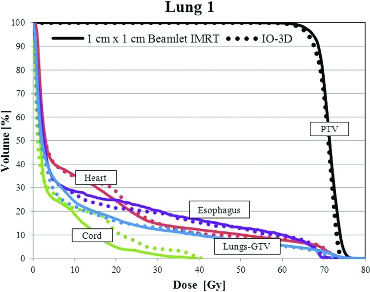
For case lung 1, the final IO-3D plan eliminated two of the original nine segments and was able to reduce the mean doses to the esophagus and the normal lung below that of the 1 cm × 1 cm IMRT plan. The IO-3D delivery efficiency was improved, requiring only 270 MU/Fx and seven segments compared to 488 MU/Fx and 149 segments for the 1 cm × 1 cm IMRT plan. The NTCP values for the lungs, heart, and esophagus showed less than 1% difference between the two plans. Dose results are shown in Fig. 10 and Table TABLE VI..
Figure 10.
DVHs for the PTV, uninvolved lung (lung-GTV), heart, spinal cord, and esophagus are shown for the 1 cm × 1 cm IMRT and IO-3D optimized plans.
TABLE VI.
Dose results and delivery efficiency for lung 1 and lung 2.
| Mean dose (Gy) | Maximum dosea (Gy) | NTCP (%) | PTV D99 (Gy) | Delivery efficiency | |||||||
|---|---|---|---|---|---|---|---|---|---|---|---|
| Structure | 1 × 1 IMRT | IO-3D | 1 × 1 IMRT | IO-3D | 1 × 1 IMRT | IO-3D | 1 × 1 IMRT | IO-3D | 1 × 1 IMRT | IO-3D | |
| Lung 1 | |||||||||||
| PTV | 71.2 | 70.6 | 76.5 | 74.5 | — | — | 63.9 | 62.9 | MU/Fx | 488 | 270 |
| Cord | 4.9 | 6.2 | 37.5 | 39.9 | — | — | — | — | Segments | 149 | 7 |
| Esophagus | 14.4 | 13.4 | 69.0 | 69.8 | 1.7 | 1.8 | — | — | Delivery time estimate (min) | 2.0 | 0.5 |
| Heart | 14.1 | 14.1 | 75.5 | 73.9 | 0.0 | 0.0 | — | — | |||
| Lungs-GTV | 10.8 | 10.2 | 92.5 | 74.0 | 5.2 | 4.7 | — | — | |||
| Lung 2 | |||||||||||
| PTV | 71.5 | 71.6 | 78.5 | 77.5 | — | — | 65.0 | 64.1 | MU/Fx | 732 | 236 |
| Cord | 10.9 | 10.8 | 47.0 | 38.0 | — | — | — | — | Segments | 308 | 6 |
| Esophagus | 16.8 | 18.3 | 72.4 | 70.7 | 12.8 | 10.5 | — | — | Delivery time estimate (min) | 4.6 | 0.4 |
| Heart | 0.9 | 1.1 | 5.8 | 9.8 | 0.0 | 0.0 | — | — | |||
| Lungs-GTV | 7.6 | 7.9 | 76.2 | 77.2 | 3.0 | 3.2 | — | — | |||
Maximum doses to 0.50 cc.
Lung 2
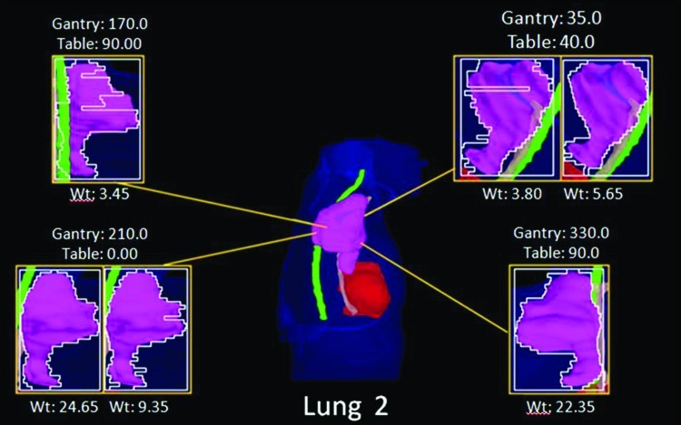
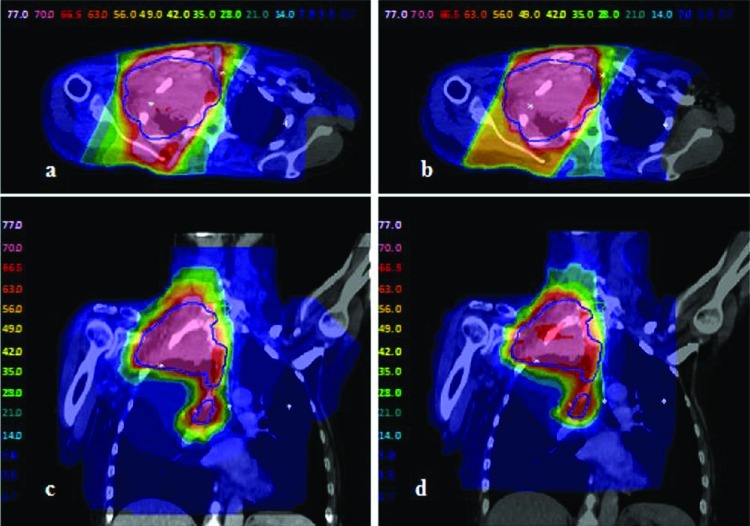
The IO-3D plan for lung 2 was planned with two segments per beam angle (ten segments total), four of which were eliminated by the IO-3D optimization (Fig. 11). As shown in Table TABLE VI., the IO-3D and IMRT plans both met the clinical planning objectives outlined in Table TABLE II.. While the mean doses for most structures in the IO-3D plan are slightly higher than those for the 1 cm × 1 cm IMRT plan, the maximum doses in the IO-3D plan are reduced below those for IMRT for all structures except the heart. NTCP values for both cases were similar and clinically equivalent; however, IO-3D was able to significantly reduce plan complexity compared to IMRT. As seen in Fig. 12, the normal tissue doses are distributed differently for the IO-3D and IMRT cases; however, PTV homogeneity is relatively similar between the two cases.
Figure 11.
BEV plots for the lung 2 IO-3D plan.
Figure 12.
Lung 2 doses for the two optimized plans: (a) and (c) 1 cm × 1 cm beamlet IMRT plan; (b) and (d) IO-3D plan.
DAO and IO-3D for one or two segments per field
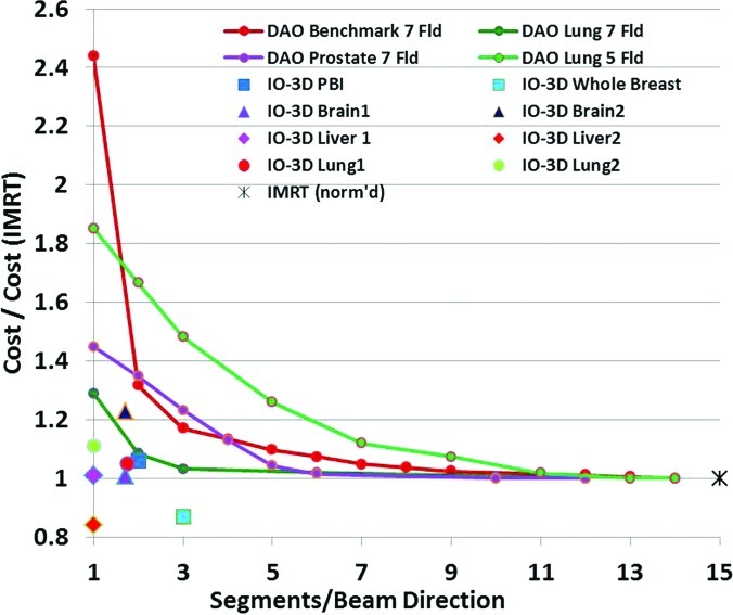
One final comparison of IO-3D and beamlet IMRT plans can be used to illustrate one of the differences between IO-3D and DAO. The paper by Jiang et al.5 is one of the only papers to describe in detail plan results obtained with DAO methods as the number of allowed segments per beam direction is decreased from a relatively large number (about 15 segments per beam) all the way to one segment per beam. The Jiang paper shows plots of the final objective function value for a series of plans with decreasing numbers of allowed segments per beam. Here, we replot some of those results in Fig. 13, with the objective function values renormalized relative to the value for the IMRT plan (the plan with the largest number of segments/beam, typically around 14 or 15). In addition to the Jiang results, Fig. 13 also shows the cost function values for several IO-3D plans relative to the cost function value of the analogous full beamlet IMRT plan. Though not all of the results from the comparisons are for the same kinds of cases and plans, the general trend is still clear: while most of the DAO plans have much larger objective function values (from 150% to 250% higher) when the number of segments/beam gets small, the IO-3D plans achieve cost functions usually within 10% or 20% of the IMRT values, for the sites studied. Clearly, of course, more complicated sites like head/neck, which have more targets, normal tissues, and costlets than the more straightforward sites involved in this work, will not be easily addressable with only one or two segments per field for either of the algorithms.
Figure 13.
Final cost (objective) function value for DAO or IO-3D plans relative to value for analogous IMRT (many segment) plan for a number of sites. DAO results replotted and renormalized from Fig. 8 of Ref. 5.
DISCUSSION
Inverse-planned IMRT has made the development of highly conformal plans routinely achievable in many clinics, since the flexibility of IMRT beams and optimization-driven inverse planning methods work well together. It has been rather difficult, however, to determine how much intensity modulation is really necessary to achieve these highly conformal plans, since the IMRT and inverse planning components are always used together. Direct comparisons between 3DCRT and IMRT have been hampered by the fact that inverse planning was used for the IMRT while interactive forward planning was used for 3DCRT plans, making comparison of goals and tradeoffs very difficult between the two very different planning techniques.
In this work, an IO-3D conformal planning method is used to optimize 3DCRT plans which consist of flat or few-segment fields, using the inverse planning technology which has been so powerful for planning IMRT fields. The IO-3D plans are compared with beamlet IMRT plans in order to investigate the relative importance of intensity modulation versus inverse planning technology for some representative kinds of planning problems and situations. The results of this simple survey of different clinical sites and plan types generally show that for relatively straightforward target volumes, IO-3D plans can achieve dosimetric results comparable to the results obtained with inverse-planned beamlet IMRT.
Using IO-3D optimization methods, plan complexity is reduced significantly when compared to beamlet IMRT. For 1 cm × 1 cm beamlet IMRT, IO-3D reduces the MU/Fx significantly, in these examples by 22%–68% compared to 1 cm × 1 cm beamlet IMRT and by 72%–84% for 0.5 cm × 0.5 cm beamlet IMRT. The IO-3D plans here used between 4 and 12 total segments (usually one or two segments per beam direction), so many fewer segments were involved than in the beamlet plans, which allowed as many as 100 segments per beam direction.
Although IO-3D has fewer degrees of freedom per beam angle than IMRT, IO-3D offers some advantages over beamlet IMRT. Probably the most important advantage of the IO-3D algorithm is the improved resolution available through the use of the edge/octree algorithm and the highly controllable optimization of MLC leaf positions. The use of the octree representation within the calculation algorithm14 gives submillimeter precision of geometric information within the calculations (at dose gradients), while the IO-3D search algorithm also allows changes in position as small as 1 mm if desired. In contrast, most beamlet or DAO algorithms are based on beamlets and pencil beams, both of which cannot afford the calculation resources to use millimeter or submillimeter geometric information.
Clearly, of course, more complex target volume–normal tissue geometries (such as head and neck cases) will often require either beamlet IMRT or more beam directions and segments if using IO-3D. IO-3D does in fact depend on 3D planning considerations, like careful choice of beam angles. As with 3D planning, changes in the choice of beam angles and initial segment designs could affect the results obtained from the IO-3D system. IMRT often has so many (extra) degrees of freedom (between the number of beams and the many beamlets and intensities which are available) that it can often generate adequate plans even if beam angles, collimator angles, and other parameters are defined in a generic way. Use of 3D planning skills can be helpful when developing IO-3D plans.
The present study has concentrated on the use of the IO-3D algorithm to investigate the differences between few-segment optimized plans and beamlet IMRT plans, rather than attempting to perform complex IMRT using optimized segments. Most other DAO (aperture) optimization work has made use of more segments per field, often basing the original segment shapes and weights on the “MLC sequencing” of a beamlet fluence optimization result [see, for example, the DMPO algorithm from PINNACLE (Ref. 21) and work by Shepard et al.4, 5]. The current IO-3D method is different in that it is designed to optimize 3DCRT plans generated with simple shaped fields (one or two segments per beam direction), rather than the usual DAO-type algorithm goals, which are either to create more efficient IMRT field deliveries or to avoid the plan degradation which occurs when an IMRT intensity distribution undergoes leaf sequencing to create the IMRT delivery trajectories for the MLC leaves. The IO-3D algorithm does not work with beamlets or fluences at all, rather, it directly uses the dose distributions calculated for each segment shape, including MLC transmission, jaw locations, and other aspects of the actual delivery geometry in the plan optimization. The dose calculations used within the IO-3D algorithm are exactly the same dose results which will be obtained with the final plan’s dose calculation.
In addition to providing simple, optimized 3DCRT plans with comparable quality to complex IMRT plans, IO-3D plans do not require the type of QA associated with IMRT plans, which can be an involved process that uses significant time and resources. Simpler plans may also prove beneficial in sites with interfraction and intrafraction motion, reducing the risk of delivering unintentional dose to normal tissues or critical structures due to patient motion. Pediatric patients may also benefit from the reduced complexity in IO-3D plans due to the reduction of overall leakage and transmission dose as well as reduced treatment time (an important concern for patients being treated under anesthesia). Finally, with the advent of adaptive replanning, IO-3D may provide a more feasible and time efficient solution than IMRT when looking to reoptimize field edges due to changes within the patient.
Additional study of the IO-3D technique should be pursued to optimize its use for clinical planning. As described earlier, the search algorithms used within the technique are important, and more efficient searches will speed the convergence of the IO-3D plans, while also assuring better performance in situations which might involve local minima in the search space. More sophisticated methods for determining the initial segment shapes and weights and for creating new segments (when useful to the optimization) can also improve the algorithm. These enhancements will be considered in the next phase of this work.
CONCLUSIONS
The automated optimization of multisegment and conformal treatment plans using IO-3D conformal planning has shown the potential for achieving high quality conformal treatment plans with flat and few-segment fields. The IO-3D plans are dosimetrically very comparable to those achieved with inverse-planned beamlet IMRT, at least for clinical targets which are not highly complex. For a number of clinical sites, the current study has demonstrated that all of the high priority goals of the cost function can be achieved with each of the techniques, though for the most complex cases, the lower priority goals may be slightly compromised for techniques with fewer degrees of freedom available to the optimization.
The current work demonstrates the importance of inverse planning in achieving the highly conformal plans developed with IMRT. The highly conformal IO-3D plans show that inverse planning is a crucial part of the treatment planning process and in many situations may be much more important than intensity modulation in the success of IMRT planning. This result suggests that it may be possible to make significantly simpler, yet highly conformal plans using the appropriate combinations of inverse planning and few-segment IO-3D plans (or other less complex intensity modulation schemes). Further work will explore the possibilities suggested by these results.
ACKNOWLEDGMENTS
The authors would like to thank Jean Moran, Ph.D., Randy Ten Haken, Ph.D., Jeff Radawski, M.D., Eduardo Acosta, Ph.D., Robin Marsh, CMD, Dan Tatro, CMD, Karen Vineberg M.S., and many others for suggestions, discussion, and treatment planning assistance. This work was partially supported by National Cancer Institute Grant No. P01-CA-59827.
References
- Moran J. M., Dempsey M., Eisbruch A., Fraass B. A., Galvin J. M., Ibbott G. S., and Marks L. B., “Safety considerations for IMRT: Executive summary,” Pract. Radiat. Oncol. 1, 190–195 (2011). 10.1016/j.prro.2011.04.008 [DOI] [PMC free article] [PubMed] [Google Scholar]
- Fraass B. A., Marks L. B., and Pawlicki T., “Safety considerations in contemporary radiation oncology: Introduction to a series of ASTRO safety white papers,” Prac. Radiat. Oncol. 1, 188–189 (2011). 10.1016/j.prro.2011.04.009 [DOI] [PubMed] [Google Scholar]
- Bogdanich W., “Radiation offers new cures, and ways to do harm,” NY Times (2010) (available URL: http://www.nytimes.com/2010/01/24/health/24radiation.html).
- Shepard D. M., Earl M. A., Li X. A., Naqvi S., and Yu C., “Direct aperture optimization: A turnkey solution for step-and-shoot IMRT,” Med. Phys. 29, 1007–1018 (2002). 10.1118/1.1477415 [DOI] [PubMed] [Google Scholar]
- Jiang Z., Earl M. A., Zhang G. W., Yu C. X., and Shepard D. M., “An examination of the number of required apertures for step-and-shoot IMRT,” Phys. Med. Biol. 50(23), 5653–5663 (2005). 10.1088/0031-9155/50/23/017 [DOI] [PubMed] [Google Scholar]
- Ahunbay E. E., Chen G. P., Thatcher S., Jursinic P. A., White J., Albano K., and Li X. I., “Direct aperture optimization-based intensity-modulated radiotherapy for whole breast irradiation,” Int. J. Radiat. Oncol., Biol., Phys. 67, 1248–1258 (2007). 10.1016/j.ijrobp.2006.11.036 [DOI] [PubMed] [Google Scholar]
- Van Asselen B., Schwartz M., Van Vliet-Vroegindeweij C., Lebesque J. V., Mijnheer B. J., and Damen E. F., “Intensity-modulated radiotherapy of breast cancer using direct aperture optimization,” Radiother. Oncol. 79, 162–169 (2006). 10.1016/j.radonc.2006.04.010 [DOI] [PubMed] [Google Scholar]
- Fraass B. A. and McShan D. L, “3-D treatment planning: I. Overview of a clinical planning system,” in International Conference on the Use of Computers in Radiation Therapy, edited by Bruinvis I., van der Giessen F., van Kleffens H., and Wittkamper F. (North Holland, Amsterdam, 1987), pp. 273–276.
- McShan D. L. and Fraass B. A., “3-D treatment planning: II. Integration of gray scale images and solid surface graphics,” in The Use of Computers in Radiation Therapy, edited by Bruinvis I. A. D., van der Giessen F. H., van Kleffens H. J., and Wittkamper F. W. (North-Holland, Elsevier Science, Amsterdam, 1987), pp. 41–44. [Google Scholar]
- Kim H., Dogan N., McShan D. L., and Kessler M. L., “An AVS-based system for optimization of conformal radiotherapy treatment plans,” in 1995 International Advanced Visual Systems User and Developer Conference, Boston, MA (Advanced Visual Systems, Boston MA, 1995), pp. 417–423.
- Kessler M. L., McShan D. L., Epelman M., Vineberg K. A., Eisbruch A., Lawrence T. S., and Fraass B. A., “Costlets: A generalized approach to cost functions for automated optimization of IMRT treatment plans,” Optim. Eng. 6, 421–448 (2005). 10.1007/s11081-005-2066-2 [DOI] [Google Scholar]
- Fraass B. A., McShan D. L., and Kessler M. L., “Dose-based conformal field shaping using automated optimization,” in Proceedings of the XIII International Conference on the Use of Computers in Radiotherapy, edited by Bortfeld T, Schlegel W, Heidelberg, Germany (Springer-Verlag, Berlin Heidelberg, Germany, 2000), pp. 32–35.
- Fraass B. A., McShan D. L., Ten R. K. Haken, and K. M. Hutchins: “3-D treatment planning: V. A fast 3-D photon calculation model,” in The Use of Computers in Radiation Therapy, edited by Bruinvis I. A. D.et al. (Elsevier Science BV, North-Holland, 1987), pp. 521–525. [Google Scholar]
- McShan D. L., and Fraass B. A., “Use of an octree-like geometry for 3-D dose calculations,” Med. Phys. 20, 1219–1227 (1993). 10.1118/1.597151 [DOI] [PubMed] [Google Scholar]
- De Gersem W., Claus F., De Wagter C., Van Duyse B., and De Neve W., “Leaf position optimization for step-and-shoot IMRT,” Int. J. Radiat. Oncol., Biol., Phys. 51, 1371–1388 (2001). 10.1016/S0360-3016(01)02607-4 [DOI] [PubMed] [Google Scholar]
- Fraass B. A., Kessler M. L., McShan D. L., Marsh L. H., Watson B., Dusseau W., Eisbruch A., Sandler H. M., and Lichter A. S., “Optimization and clinical use of multisegment IMRT for high dose conformal therapy,” Semin. Radiat. Oncol. 9, 60–77 (1999). 10.1016/S1053-4296(99)80055-1 [DOI] [PubMed] [Google Scholar]
- Mackie T. R., Scrimger J. W., and Battista J. J., “A convolution method of calculating dose for 15-MV x rays,” Med. Phys. 12, 188–196 (1985). 10.1118/1.595774 [DOI] [PubMed] [Google Scholar]
- Coselmon M. M., Moran J. M., Radawski J., and Fraass B. A., “Improving IMRT delivery efficiency using intensity limits during inverse planning,” Med. Phys. 32, 1234–1245 (2005). 10.1118/1.1895545 [DOI] [PubMed] [Google Scholar]
- Matuszak M. M., Larsen E. W., and Fraass B. A., “Reduction of IMRT beam complexity through the use of beam modulation penalties in the objective function,” Med. Phys. 34, 507–520 (2007). 10.1118/1.2409749 [DOI] [PubMed] [Google Scholar]
- Matuszak M. M., Larsen E. W., Jee K.-W., McShan D. L., and Fraass B. A., “Adaptive diffusion smoothing: A diffusion-based method to reduce IMRT field complexity,” Med. Phys. 35, 1532–1546 (2008). 10.1118/1.2889703 [DOI] [PMC free article] [PubMed] [Google Scholar]
- Löf J. and Rehbinder H., Inverse Planning Optimization with RayOptimizer in Pinnacle (RaySearch White Paper RaySearch Laboratories AB, Stockholm, Sweden, 2002). [Google Scholar]


