Introduction
A recent publication from this laboratory (1) reported a theoretical analysis comparing approaches for creating harmonic ICR cells. We considered two examples of static segmented cells – namely, a seven segment cell developed in this laboratory (2) and one described by Rempel et al (3), along with a recently described dynamically harmonized cell (4). This conceptual design for a dynamically harmonized cell has now been reduced to practice and first experimental results obtained with this cell were recently reported in this journal; this publication (5) reported details of cell construction and described its performance in a 7 Tesla Fourier Transform mass spectrometer. Herein, we describe the extension of theoretical analysis presented in (1) to include angular-averaged radial electric field calculations and discuss the influence of trapping plates.
Potential calculations for the dynamically harmonized cell
The dynamically harmonized cell uses leaf-shaped cut-outs in the cell cylinder and is fitted with specially shaped end caps. The leaf cell configuration treated here is made up of 8 ‘leaves’ and 8 complementary elements, or c-leaves, as described elsewhere in detail (4, 5). All leaves are DC-grounded, and c-leaves have trapping potential Vtrap applied. We utilize the same configuration modeled in our earlier report (1) and summarized here.
The polar angle period is
| (1) |
The leaf geometry is defined by the quadratic function:
| (2) |
Here a(z) is the leaf width expressed in units of the polar angle period Ap. The origin of the x, y, z coordinate system is placed at the cell center, with z directed along the cell axis. The a0 term and coefficient k are chosen to set the initial and final leaf width.
Leaves:
| (3) |
| (4) |
C-leaves:
| (5) |
| (6) |
The coefficient k is −0.175 for leaves and 0.175 for C-leaves.
The gap between a leaf and a c-leaf is 0.1 Ap; for cell radius Rc = 30 mm this corresponds to the gap width 0.1·Ap Rc = 2.356 mm.
The cylinder extends from −zmax to +zmax. The modeled configuration has
| (7) |
in units of the inner cell radius Rc. The cell aspect ratio, defined as the ratio of the cylinder length to its diameter, is
| (8) |
The shaped elements forming the cell cylinder generate an angular-dependent trapping DC potential well throughout the cell volume; angular averaging (4) experienced by ion clouds executing cyclotron motion results in a nearly ideal quadratic potential. Trapping plates for such a cell would ideally be shaped according to boundary conditions of the angular-dependent potential throughout the cell volume, which can be achieved by angular segmentation of the end caps. It was asserted in the original formulation (4) that the length of the cell made segmenting unnecessary and that classical hyperbolic end caps can be employed. This point is addressed in the present simulation of two quite different trapping plate configurations affecting the angular averaged radial electric field in such a cell.
Trapping plates were included in our previous simulations (1), but we did not discuss their influence explicitly; rather we concentrated on field behavior inside the cell volume. We now consider two end cap configurations explicitly—flat end caps and shaped end caps similar to those utilized in the fabricated dynamic cell (5)—and their influence on cell harmonicity as a function of distance from the center of the cell.. Although the actual cell (5) has spherical end caps and an aspect ratio of 2.7, while the modeled cell has hyperbolic end caps and an aspect ratio of 2, qualitative features described here are unlikely to be altered by these differences.
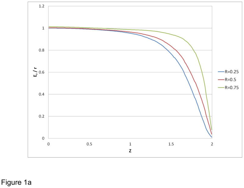
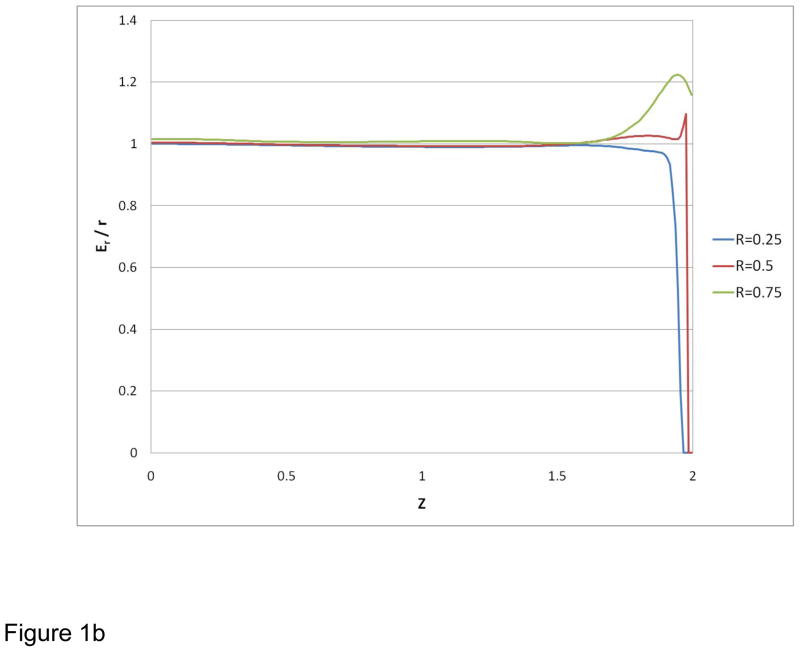
Normalized field homogeneity results are presented for two examples in Figure 1 as axial profiles of the angle-averaged radial electric field divided by radius, Er/r. For configurations having cylindrical symmetry, such as open cylindrical cells (2) and (3), the radial electric field intensity Er is equal to the absolute value
Figure 1.
Radial electric field divided by radius, angle-averaged, normalized to the value at z = 0, r = 0.25. Axial profiles for three radial positions: 0.25, 0.5 and 0.75. (a) Results are shown for configuration using flat end caps (a) and configuration using hyperbolically-shaped end caps (b).
| (9) |
of the field vector projection on the X–Y plane, having two components Ex and Ey.
In contrast, the dynamically harmonized cells possess a non-zero, angular-dependent tangential electric field component, and the radial field intensity Er is calculated differently:
| (10) |
The electric field intensity components Ex and Ey were calculated as derivatives of potential over corresponding coordinates. Potential calculations were performed using a potential array relaxation numerical solution of the Laplace equation. The accuracy of our calculations was evaluated by comparing results obtained with a fine step, 0.005 (Rc units) and a rough step of 0.01. The relative difference in Er/r values was on average ~4%,, which represents inaccuracy of the rough step calculations. Results in Figures 1a and 1b were obtained using the fine step, ensuring much better accuracy.
Figure 1a illustrates the effect of placing flat end caps at the ends of the ICR cell cylinder on field homogeneity throughout the active volume of the cell. Flat end caps were positioned at an axial offset of 0.01 Rc, 0.02 Rc thick, and included a centrally located orifice with internal diameter 0.1 Rc; a flat DC grounded boundary plane was positioned at z = 2.08 Rc. The end caps were biased to Vend = 0.9 Vtrap for this configuration.
Figure 1b used hyperbolic end caps, shaped according to the equipotential surface of the ideal cell (2):
| (11) |
These end caps have cylindrical inlets, internal diameter 0.1 Rc and a flat DC grounded boundary plane was positioned at z = 2.08 Rc. The end cap potential is Vend = 0.9 Vtrap. This geometry corresponds closely to the spherical end caps utilized in the experimentally tested dynamically averaged harmonic cell (5) to approximate the ideal hyperbolic profile.
Even for the simplest case of a perpendicularly defined potential, Fig. 1a, the leaf cell provides essentially ideal Er/r profiles over a significant fraction of the cell volume. The effect of utilizing ideal, hyperbolically shaped trapping plates is shown in Figure 1b. This modification significantly extends the length of harmonized cell volume and clearly provides improved axial field distributions that may account for the impressive performance reported for this particular cell design (5).
Conclusions
Our previous report (1) analyzed alternative cell harmonization concepts, using the spatial behavior of the radial electric field divided by radius (Er/r) as a metrics. This Communication extends our approach to include explicitly angle-averaged Er/r profiles. The approach has been applied to the dynamic harmonization cell concept (4, 5) to characterize the trapping potential improvement produced by both the leaf-shaped elements and the hyperbolically shaped end caps. Figure 1a shows that the leaf elements themselves provide on-average harmonization for most of the cell length, even when flat end caps are used. Figure 1b demonstrates that hyperbolically shaped end caps extend the field harmonization effect essentially throughout the cell volume. The present theoretical results provide insights that advance our understanding of the performance of the dynamically harmonized leaf cell design (5). The angular averaging of the radial field, implemented here with the dynamic harmonization assumption, verifies the uniform, in terms of Er/r, trapping field distribution across the cell volume, in agreement with the original formulation for dynamic harmonization presented in (4). Further theoretical analysis and experimental testing of both static and dynamically harmonized cell designs at higher magnetic fields are in progress and will be reported at a later date.
Acknowledgments
The authors acknowledge that portions of this work were supported by the US Department of Energy (DOE) Office of Biological and Environmental Research and by the NIH National Center for Research Resources (RR018522). Work was performed in the Environmental Molecular Science Laboratory (EMSL), a DOE national scientific user facility located on the campus of Pacific Northwest National Laboratory (PNNL) in Richland, Washington. PNNL is a multi-program national laboratory operated by Battelle for the DOE under contract DE-AC05-76RLO 1830.
References
- 1.Tolmachev AV, Robinson EW, Wu Si, Smith RD, Pasa-Tolic L. Trapping Radial Electric Field Optimization in Compensated FTICR cells. J Am Soc Mass Spectrom. 2011;22:1334–1342. doi: 10.1007/s13361-011-0167-z. [DOI] [PubMed] [Google Scholar]
- 2.Tolmachev AV, Robinson EW, Wu S, Kang H, Lourette NM, Pasa-Tolić L, Smith RD. Trapped-ion cell with improved DC potential harmonicity for FT-ICR MS. J Am Soc Mass Spectrom. 2008;19:586–597. doi: 10.1016/j.jasms.2008.01.006. [DOI] [PMC free article] [PubMed] [Google Scholar]
- 3.Brustkern AM, Rempel DL, Gross ML. An electrically compensated trap designed to eighth order for FT-ICR mass spectrometry. J Am Soc Mass Spectrom. 2008;19:1281–1285. doi: 10.1016/j.jasms.2008.05.016. [DOI] [PMC free article] [PubMed] [Google Scholar]
- 4.Boldin IA, Nikolaev EN. Fourier transform ion cyclotron resonance cell with dynamic harmonization of the electric field in the whole volume by shaping of the excitation detection electrode assembly. Rapid Commun Mass Spectrom. 2011;25:122–126. doi: 10.1002/rcm.4838. [DOI] [PubMed] [Google Scholar]
- 5.Nikolaev EN, Boldin IA, Jertz R, Baykut G. Initial Experimental Characterization of a New Ultra-High Resolution FTICR Cell with Dynamic Harmonization. J Am Soc Mass Spectrom. 2011;22:1125–1133. doi: 10.1007/s13361-011-0125-9. [DOI] [PubMed] [Google Scholar]


