Abstract
Total disc replacements (TDRs) have been employed with increasing frequency in recent years with the intention of restoring natural motion to the spine and reducing adjacent level trauma. Previous assessments of the TDRs have subjectively measured patient satisfaction, evaluated sagittal range of motion via static imaging, or examined biomechanical loading in vitro. This study examined the kinematics and biomechanical loading of the lumbar spine with an intact spine compared to a TDR inserted at L5/S1 in the same spine. A validated biologically driven personalized dynamic biomechanical model was used to assess range of motion (ROM) and lumbar spine tissue forces while a subject performed a series of bending and lifting exertions representative of normal life activities. This analysis concluded that with the insertion of a TDR, forces are of much greater magnitude in all three directions of loading and are concentrated at both the endplates and the posterior element structures compared to an intact spine. A significant difference is seen between the intact spine and the TDR spine at levels above the TDR insertion level as a function of supporting an external load (lifting). While ROM within the TDR joint was larger than in the intact spine (yet within the normal ranges under the unloaded bending conditions), the differences between spines were far greater in all three planes of motion under loaded lifting conditions. At levels above the TDR insertion, larger ROM was present during the lifting conditions. Sagittal motions were often greater at the higher lumbar levels, but there appeared to be less lateral and twisting motion. Collectively, this analysis indicates that the insertion of a TDR significantly alters the function of the spine.
Keywords: Artificial disc, Biomechanics, Kinematics, Kinetics, Lumbar spine
Introduction
Total disc replacements (TDRs) are rapidly becoming an alternative to fusion surgery. When a diseased disc is removed, these so-called “motion sparing” devices are inserted into the disc space with the intention of replicating the movements of a normal disc and restoring normal function to the spine [1]. This procedure is intended to overcome some of the potential shortcomings of fusion surgeries such as adjacent level disc degeneration [2–5]. Total lumbar spine motion is dictated by the tasks that one is attempting to accomplish regardless of low back health status [6]. If a functional spinal unit is fused, the resultant total spine motion is achieved through the use of adjacent non-fused spine segments attempting to compensate for the spine’s total kinematic demand. This increased adjacent level demand can lead to increased disc degeneration in these neighboring discs [4, 7]. TDR is an attempt to restore normal range of motion and normal loading to these adjacent discs.
The reported success rates for TDRs are varied. Short-term studies have reported decreases in back and leg pain as well as improved function for mechanical low back pain [8, 9]. Long-term follow-ups have reported varied success rates with some reporting serious complications with nearly half of the TDRs requiring removal [10]. Others report degeneration of the discs and facets [11]. By comparison, a 10-year follow-up reported that 90% of patients rated their outcomes to be good or excellent [12]. Unlike fusion, facet degeneration risk appears to be greater at the TDR insertion site level [13]. The number of levels replaced also appears to influence success rates [14, 15]. One (level 1) randomized controlled study concluded that the TDR was superior to fusion [16].
Quantitative biomechanical assessments of TDRs have evaluated segmental range of motion (ROM) or segmental kinetics (tissue loading). Imaging studies investigating ROM of the functional spinal unit report different findings for single level versus multiple level TDRs. Single level TDRs result in relatively normal kinematics, whereas TDRs in adjacent levels results in abnormal kinematic activities [17]. Increased ROM at the artificial disc level increases degeneration [2, 18]. A closer examination of the “normal” motions reported in some of these studies suggests subtle but important differences in segmental motion. The lack of physical constraints in TDRs may lead to excessive facet joint or capsuloligament loads in extreme flexion and extension [19] resulting in more axial rotation [20]. Altered kinematics can result in greater flexion angles when exposed to much lower moments [21] suggesting some profound biomechanical trade-offs associated with “normal” TDR kinematics.
In vitro studies have been employed to explore the biomechanical implications of TDRs. While normal ROM has been observed under physiologic loading, it resulted in different segmental motion compared to an intact spine [22]. Facet contact forces at the TDR level are altered [23], whereas decreased facet loads at adjacent levels are reported [24]. Coupling among the facets appears to be eliminated with artificial discs [23, 25], and excessive facet forces have been reported using traditional finite element modeling of cadaveric specimens [26]. The design of the TDR also appears to influence the loading that occurs at the facets [23]. Finally, placement and the height of the TDR appear to be important considerations for biomechanical function [27–29].
Collectively these studies indicate that the facet loads at the level of the TDR as well as the forces on discs and facets at adjacent levels are the keys to understand the cost-benefit of artificial discs. However, the biomechanical studies regarding tissue loads are based on cadaver studies. While these studies are useful in estimating loads based upon static moment loading, none have attempted to interpret the biomechanical consequences of spinal loading during in vivo dynamic activities. The current study attempted to overcome this shortcoming by comparing spine load distribution in an intact spine relative to spine loads resulting from a TDR during real life-task performance.
Methods
Subject testing
One male subject was modeled with and without a ProDisc™ virtually inserted at L5/S1. The subject was 24 years of age, 179 cm tall, and 74.8 kg in weight. The subject was generally of good health and free of any obvious pathology.
Tasks
Twenty-one tasks of various intensities were performed in order to assess the biomechanical behavior of the lumbar spine. All tasks involved primarily sagittal plane bending. Thirteen of these tasks consisted of bending from an upright standing position to a flexed position. No weight (other than bodyweight) was supported during these 13 exertions. Four exertions involved the lifting of a 9.5-kg mass from flexed positions to upright standing positions. Another four exertions consisted of lifting 19 kg. In all these exertions, the subject was asked to move at a normal pace.
Dependent measures
The various experimental conditions compared spine force distribution within the intact spine versus a TDR inserted at L5/S1 based upon several functional biomechanical and kinematic measures. These measures can be seen in Table 1.
Table 1.
Biomechanical model outputs
| Disc tissue loads | Ligament forces | Facet loads | Intervertebral range of motion |
|---|---|---|---|
| Superior endplate compression | Anterior longitudinal ligament (ALL) | Right facet load | Sagittal |
| Superior endplate anterior/posterior (A/P) shear | Interspinous ligament (ISF) | Left facet load | Lateral |
| Superior endplate lateral shear | Ligamentum flavum (LF) | Transverse | |
| Inferior endplate compression | Posterior longitudinal ligament (PLL) | ||
| Inferior endplate anterior/posterior (A/P) shear | Right intertransverse ligament (R TL) | ||
| Inferior endplate lateral shear | Left intertransverse ligament (L TL) | ||
| Supraspinous ligament (SSL) | |||
| Right capsular ligament (R CL) | |||
| Left capsular ligament (L CL) |
Procedures
After providing informed consent, subject anthropometry was collected, and the subject was prepared for testing through the application of surface electrodes to the torso muscles to document trunk muscle activities and through the application of a lumbar motion monitor to measure three-dimensional torso motion. Detailed descriptions of subject preparation for such testing have been given previously [30]. After calibration, the subject was asked to perform the experimental tasks previously described.
Biomechanical modeling of the lumbar spine
Model development
The model used to assess spine tissue loading is unique in that it is person-specific in terms of anthropometry (muscle location and size), subject motion (trunk as well as limb motion), and muscle activities. Over the past 25 years this model has been validated across a wide range of different exertions and test conditions [31–40]. Recently, the model was updated to be sensitive to a wider range of dynamic exertions and has also been embedded into the ADAMS (MSC Software) multi-body dynamic software environment [41].
While this model provided a clear picture of the spine system’s response to various biomechanical loads, more tissue detail was necessary to evaluate the impact of surgical procedures on the spine. Traditionally, these types of analyses were performed with finite element modeling (FEM). Unfortunately, the great computational demands inherent in FEM usually restrict models to only small portions of the spine and either static or short duration quasi-dynamic analyses. These models also usually simplify the representation of the lumbar musculature. The lack of realistic muscle representation and dynamic loading limits FEM’s utility in accurately representing the entire system of the lumbar spine and its response to surgical interventions, particularly interventions that are dynamic in nature.
With the intention of overcoming the limitations of the existing dynamic biomechanical model and traditional FEM, the existing biomechanical model has been further developed to include much greater anatomic detail and to take advantage of flexible multi-body dynamics [42]. Flexible multi-body dynamics in ADAMS uses component mode synthesis methodology [43], which greatly reduces an FEM’s computational complexity with a minimum loss of accuracy [44] while allowing large overall motion and complex interaction with other elements. Ultimately, this allows complex structures, such as the intervertebral disc, which normally could only be modeled with FEM, to be accurately represented as a flexible body in a dynamic model.
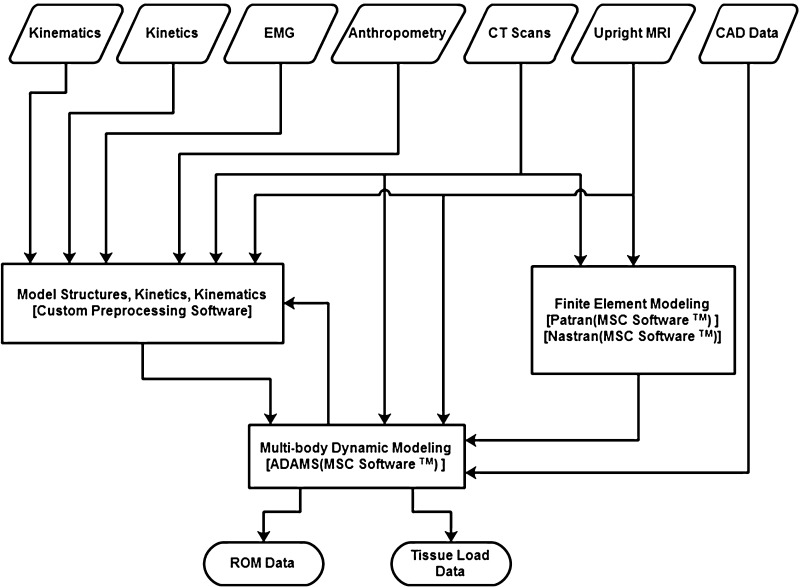
In order to generate the subject-specific model, multiple sources of imaging data were obtained. First, the subject underwent a series of computed tomography (CT) scans that were then segmented into a detailed three-dimensional model of the full lumbar spine from T12 to the sacrum. In order to correct the subject’s spine posture from the recumbent CT scan, the subject was also imaged in an Upright Multi-Position MRI (Fonar Corporation™) while standing erect. The three-dimensional spine model was then realigned to match the standing posture. Each of the vertebral bodies and sacrum were then imported into the ADAMS software environment as rigid bodies. MRI and CT scan data were also used to reconstruct the intervertebral discs. In order to create the flexible bodies, a finite element model of the disc was first created in PATRAN (MSC Software). In the disc model, the annulus fibrosus was modeled as a composite material with fibers embedded in a ground substance. The fibers were arranged in a series of alternating layers oriented 30° to the transverse plane. The nucleus pulposus was modeled as essentially an incompressible fluid. The vertebral endplates were modeled with shell elements. The material properties of each portion came from values in the literature [45–47]. A normal modes analysis with an included preload was conducted on the disc model in Nastran (MSC Software) to create a flexible body for ADAMS. The preload was calculated from the subject’s upper torso mass and the muscle force calculated from EMG data of the subject while standing erect in a neutral posture. Each flexible body disc was rigidly attached to the vertebral bodies adjacent to it. The ligaments were modeled as nonlinear spring forces with material properties and insertion points from literature [48]. The facet joints were modeled with nonlinear three-dimensional contact forces available in ADAMS with parameters from previous studies [49]. The lumbar musculature is represented with a series of active force vectors driven with EMG. The algorithms are retained from the previous validated EMG-assisted model [41]. The cross-sectional areas of the muscles and the locations of their origin and insertions are from a large database of MRI scans supplemented with the subject’s own upright scans. A diagram of the model is shown in Fig. 1.
Fig. 1.
Biomechanical model structure and component interactions
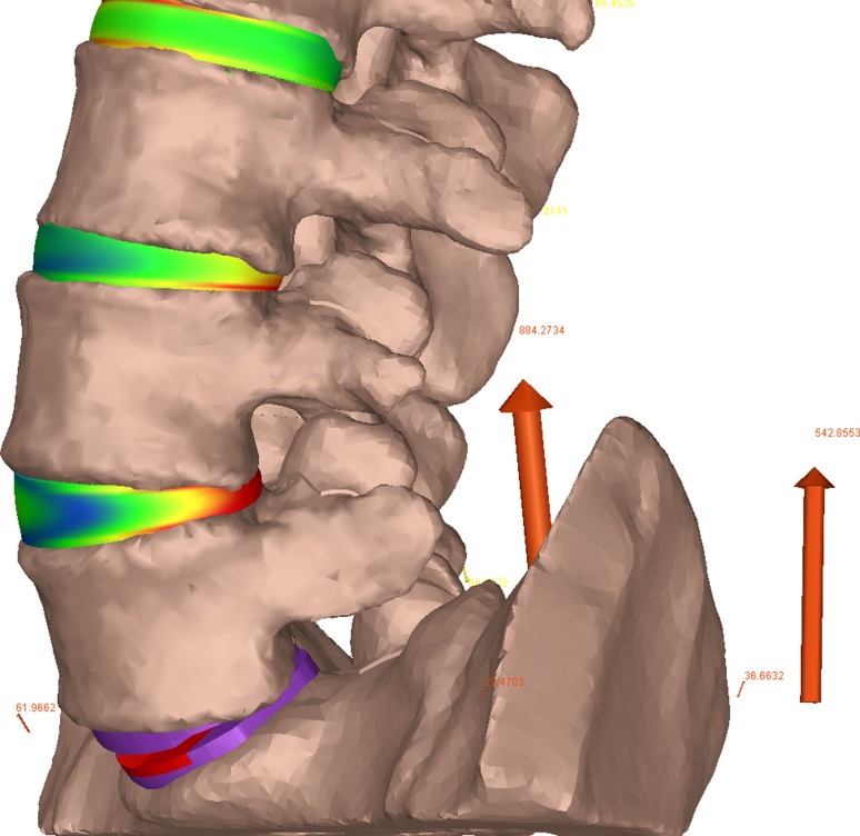
In the TDR spine model, the L5/S1 disc was completely removed and a 6° Synthes ProDisc prosthesis with a height of 10 mm installed in its place. CAD models of the intact spine and the artificial disc were created so that an experienced neurosurgeon (EM) could perform a “virtual surgery” to ensure proper placement consistent with the manufacturer’s guidelines [51]. Consistent with the anterior approach for the implantation, the anterior longitudinal ligament was removed in the TDR model. The artificial disc was modeled as a series of rigid bodies fixed to the adjacent vertebrae with a three-dimensional nonlinear contact force between the contacting surfaces. A coefficient of friction of 0.05 was used at the surface interface [50]. The model is shown graphically in Fig. 2.
Fig. 2.
Model representations of the TDR spine
Model validation
In order to confirm the validity of the model for this particular subject, two methods of in vivo validation were employed. First, the resultant dynamic moment resulting from muscle activations was compared (via R2 and average absolute error) to the external moment to which the body was exposed. The model performed well with an average R2 value of 0.93 across all trials, while the average absolute error was about 1% of the external moment. The second validation compared the model-predicted vertebral kinematics to those measured directly from imaging data of the subject placed at various trunk flexion angles in the upright MRI. The overall average absolute error value between the model-predicted and imaging intervertebral angles, for all the trials, was only 0.886°. Given the ability to match measured and predicted external loads and intervertebral kinematics, this model was considered a valid predictor of spine tissue forces.
Results
Given the massive amounts of data generated in analyzing these various task conditions, the results can be best be reported through descriptive statistics (mean and standard deviations) that directly compare the intact spine with the same spine where the TDR was inserted at L5/S1. The following sections make this comparison as a function of the various spine loading conditions.
Trunk bending (unloaded spine)
Tissue load distribution along the lumbar spine
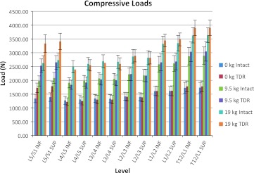
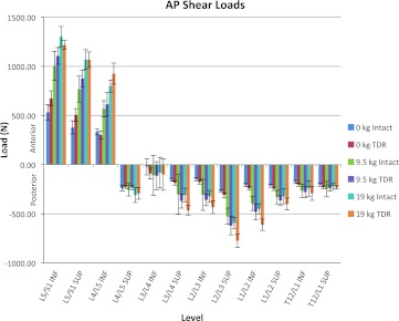
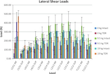
Figures 3, 4, and 5 show the average of the peak compressive, A/P shear, and lateral shear forces, respectively, acting on the superior and inferior portions of the lumbar discs as a function of the intact spine versus the lumbar spine with the TDR inserted at L5/S1. Figure 3 indicates that during unloaded bending (non-lifting) the L5/S1 junction endplates are subjected to approximately 28% more compressive load in the TDR spine, whereas the rest of the lumbar spine experiences approximately equivalent loadings with or without the TDR insertion. Figure 4 indicates a similar trend in terms of A/P shear. The L5/S1 junction experiences 27–34% greater shear during unloaded bending at the inferior and superior endplate surfaces, respectively, with the TDR inserted at L5/S1. The lumbar disc forces above these levels are generally more comparable with the TDR conditions experiencing slightly greater forces. An exception to this was L3/L4 where the disc experienced much greater forces although of low magnitude. The lateral shear forces imposed upon the spine were most different between the intact spine and the TDR spine and shown in Fig. 5. Of interest is the excessive relative loading at the inferior L5/S1 level where the TDR spine experienced on average over three times the loading compared to the intact disc. In contrast, the intact lumbar spine above this level experienced increased lateral shear compared to the TDR spine with the magnitude of the average difference approaching 40–50% greater loading in the upper lumbar spine levels.
Fig. 3.
Average of the peak compression loads on the lumbar spine endplates as a function of intact spine versus TDR spine and external loading condition (bending while unloaded 0 kg, lifting 9.5 kg, lifting 19 kg)
Fig. 4.
Average of the peak anterior/posterior (A/P) shear loads on the lumbar spine endplates as a function of intact spine versus TDR spine and external loading condition (bending while unloaded 0 kg, lifting 9.5 kg, lifting 19 kg)
Fig. 5.
Average of the peak lateral shear load magnitudes on the lumbar spine endplates as a function of intact spine versus TDR spine and external loading condition (bending while unloaded 0 kg, lifting 9.5 kg, lifting 19 kg)
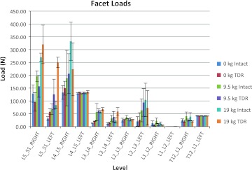
Facet loads are displayed in Fig. 6. For this subject, there appears to be an asymmetry present with the L5/S1 structures being loaded to a greater extent on the right side compared to the left. This asymmetry is due, in part, to the unique geometry of the facet joint for this particular subject. This further illustrates the value of a detailed subject-specific model since it is able to account for each subject’s unique anthropometry and loading characteristics. Here, again the presence of the TDR appears to have the greatest influence at the level of the insertion with lower contact forces occurring in the TDR spine on the right side at L5/S1 and greater occurring on the left-side structures at L5/S1. The differences are much less dramatic at the levels above L5/S1.
Fig. 6.
Average of the peak facet contact forces as a function of intact spine versus TDR spine and external loading condition (bending while unloaded 0 kg, lifting 9.5 kg, lifting 19 kg)
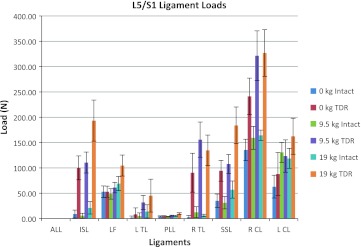
Spinal ligament loads are shown in Fig. 7 for these simple bending activities. Notably large ligament loads are evident for the TDR spine compared to the intact spine for nearly all the ligaments at the L5/S1 level. The RCL ligament loads were particularly great for the TDR spine during the unloaded bending conditions. Most of the differences in ligament forces between the two spines occur at L5/S1, whereas the differences are much less at the levels above the TDR level.
Fig. 7.
Average of the peak ligament tensions at the L5/S1 level as a function of intact spine versus TDR spine and external loading condition (bending while unloaded 0 kg, lifting 9.5 kg, lifting 19 kg)
Intervertebral ROM
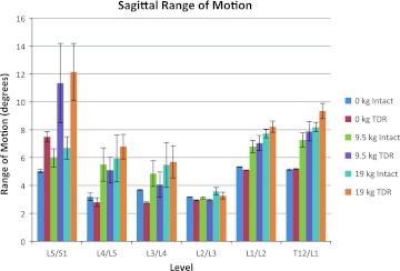
Figure 8 shows the ROM at each lumbar level in the sagittal plane occurring during the exertions for the intact spine compared to the TDR spine. The ROM of L5/S1 was nearly 49% greater in the TDR spine compared to the intact spine during the unloaded bending activities. Changes in the vertebral angles above the L5/S1 lumbar levels were generally moderate in magnitude with the intact spine producing slightly more ROM than the TDR spine up to the L2/L3 level. ROM occurring at L1/L2 and at L1/T12 during the unloaded bending trials was comparable to that of the intact spine level at L5/S1 regardless of spine condition.
Fig. 8.
Mean sagittal plane range of motion (ROM) at each lumbar level as a function of intact spine versus TDR spine and external loading condition (bending while unloaded 0 kg, lifting 9.5 kg, lifting 19 kg)
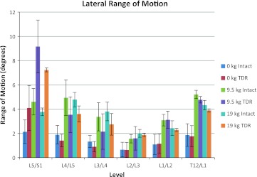
The lateral ROM occurring during the tasks is shown in Fig. 9. This figure indicates that there are large lateral angle changes occurring in the TDR spine relative to the intact spine at L5/S1, whereas at the intervertebral levels above L5/S1 there is slightly more lateral plane motion in the intact spine or no difference between the spines.
Fig. 9.
Mean lateral plane range of motion (ROM) at each lumbar level as a function of intact spine versus TDR spine and external loading condition (bending while unloaded 0 kg, lifting 9.5 kg, lifting 19 kg)
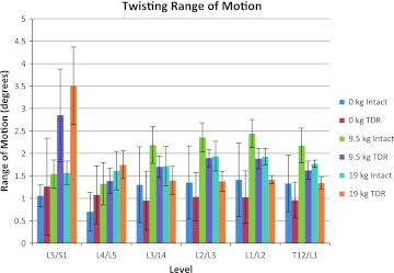
The twisting plane ROM is shown in Fig. 10. Under unloaded bending conditions, twisting ROM was slightly greater at L5/S1 and L4/L5 in the TDR spine compared to the intact spine with the reverse trend occurring above the L4/L5 level.
Fig. 10.
Mean twisting (transverse) plane range of motion (ROM) at each lumbar level as a function of intact spine versus TDR spine and external loading condition (bending while unloaded 0 kg, lifting 9.5 kg, lifting 19 kg)
Trunk bending while lifting (loaded spine)
Tissue load distribution along the lumbar spine
Figures 3, 4, 5, 6, 7, and 8 also indicate how the spine functions when lifting the 9.5 and 19 kg loads in the intact spine compared to the TDR spine. As expected compression loads increased by a greater amount in the TDR spine compared to the intact spine as weight lifted increased (Fig. 3). This increase was most prominent at L5/S1. When lifting either the 9.5 or 19 kg loads, the spine compression at L5/S1 increased by around 28% in the TDR spine compared to the intact spine. Differences between the two spines at levels above L5/S1 were much more modest and generally within 7% or less of each other. A/P shear forces increased greatly when lifting weights compared to the unloaded spine bending condition (Fig. 4). Substantial shear forces were noted in the superior and inferior surfaces of L5/S1. These shear forces were not as clearly associated with the TDR spine as was noted with compression. Shear forces at spine levels above the superior L4/L5 level were generally more moderate in magnitude. Lateral shear forces were markedly greater at the L5/S1 inferior endplate level for the TDR spine compared to the intact spine regardless of the weight handled (Fig. 5). These loads were generally doubled in the TDR spine. There appeared to be a large redistribution of lateral shear loading in the levels above L5/S1 in the intact spine relative to the TDR spine with the intact spine supporting more of the lateral shear loads at these levels, whereas the load was supported more at L5/S1 in the TDR spine. Lateral shear loads were actually greater at these levels when lifting the 9.5 kg load than when lifting the 19 kg loads for this subject. This most likely indicates the truly unique nature of spine loading for a given individual. In-depth analysis indicated that the subject was more asymmetric when performing these tasks (see Figs. 9, 10).
Facet loads were greatest at the lower lumbar levels and particularly at the site of the TDR junction (Fig. 6). There appeared to be a left–right trade-off in load occurring in the facets that varied as a function of load at these lower levels. The L5/S1 right facet experienced greater contact forces with the intact spine for the unloaded and 9.5 kg conditions. However, the reverse was true for the 19 kg lifting conditions. Left-side facet contact forces were always larger for the TDR spine at L5/S1. This was generally the case at L4/L5 right facet contact force except for the 19 kg lifting conditions. All other facet contact forces were fairly low in magnitude and generally consistent in pattern regardless of the condition.
Most ligament forces were notably greater at the L5/S1 level for the TDR spine compared to the intact spine, and the magnitude of these ligament forces was often greatest for the 19 kg lifting condition (Fig. 7). The ligament tensions at the levels above L5/S1 were generally much lower than at the TDR insertion level.
Intervertebral ROM
Figure 8 indicates the change in intervertebral ROM as a function of the spine condition and lifting condition. Large sagittal plane ROM differences occurred between the intact spine and the TDR spine at the L5/S1 intervertebral level during lifting conditions with the ROM generally doubling under the TDR spine condition compared to the intact conditions. For the levels above L5/S1, there was little difference between the intact and TDR spines. There were, however, significant increases in ROMs at L4/L5, L3/L4, L1/L2, and T12/L1 with lifting compared to the pure bending (unloaded) conditions. Figure 9 indicates very large increases in L5/S1 lateral ROM in the TDR spine compared to the intact spine under both lifting conditions with greater angle changes occurring at the 9.5 kg lifting condition compared to the 19 kg lifting condition. There appears to be a trade-off in ROM for the intervertebral discs above this level with the intact spine showing slightly greater motion than the TDR spine. However, the magnitudes of these angle changes are generally significantly lower compared to those at the L5/S1 level.
Figure 10 indicates twisting plane ROM changes as a function of the lifting conditions. The L5/S1 vertebrae indicated a pattern similar to that seen in the lateral plane during lifting. L5/S1 twisting ROM was far greater in the TDR spine compared to the intact spine. A similar pattern, but of much lesser magnitude, was also noted at L4/L5. Above this level, twisting motion was generally greater for the intact spine compared to the TDR spine. However, these were generally of much lesser magnitude compared to the L5/S1 level TDR spine.
Discussion
The objective of this analysis was to assess how a TDR inserted at L5/S1 would compare to an intact spine when a person was performing tasks associated with normal living activities including normal unloaded bending as well as lifting objects of moderate load magnitude. Where most previous studies have compared the TDR to fusion, we were able to compare the TDR to an intact spine, which should provide some guidance for how TDR technology needs to improve in the future. We believe this will provide insight into how future designs of TDRs should be directed to mimic the function of the intact spine.
This assessment was unique because we were able to perform a detailed dynamic in vivo biomechanical analysis (both kinetically and kinematically) of lumbar spine loads and kinematic function comparing between the two spines using a validated “personalized” biologically assisted hybrid biomechanical model. The benefit of this personalized model is that we were able to assess the unique influence of the degenerative features of the specific subject. In addition, with a personalized model, we were able to assess the influence of only the TDR since everything else in the assessment remained the same. In this analysis, we assessed 100 load variables and 18 kinematic variables under each condition. Thus, we were able to assess the biomechanics at a level of granularity that has rarely been reported previously.
Using this analysis technique we were able to come to several conclusions. First, with the insertion of a TDR, forces are of much greater magnitude in all three directions of loading and are concentrated at both the end plates and the posterior element structures compared to an intact spine. Increased compression loads within the TDR spine compared to the intact spine are of the order of around 30% greater regardless of whether the spine is supporting an external load or not. However, a significant difference is seen between the intact spine and the TDR spine at levels above the TDR insertion level as a function of supporting an external load (lifting). Without external loading, the differences between the intact spine and the TDR spine are minor at levels above L5/S1; however, with loading at the upper lumbar spine, the TDR spine experiences greater compressive loading (5–7%) compared to the intact spine. These differences were much smaller (around 2%) with the unloaded condition. Significant increases in lateral shear force in the TDR spine compared to the intact spine were seen particularly at the inferior endplate of the insertion level. These forces often were twice as great in the TDR spine compared to the intact spine. Some of the greatest lateral shear magnitudes at lumbar levels above the TDR insertion level were seen in the intact spine when lifting the 9.5 kg external load. Similar patterns occurred in response to the other external loading conditions. We suspect this was due to the unique way that this subject employed his torso muscles during these exertions. This emphasizes the systems behavior of the lumbar spine. There also appeared to be a trade-off of lateral shear at the insertion level with the facet forces at this same level. It was interesting to note that the introduction of the TDR seemed to balance out the facet loads removing much of the asymmetry due to the subject’s specific vertebral geometry. This analysis also indicates that the capsular ligaments are exposed to significant loads in the TDR spine. In addition, there is an asymmetry to the loading in these ligaments on the right versus left sides that are also associated with the facet loading pattern. Collectively, this analysis indicates that the insertion of a TDR significantly alters the function of the spine.
This analysis also sheds light on the kinematic behavior of the vertebrae in three-dimensional space when a TDR is inserted at a disc level compared to an intact spine. No previous studies have explored vertebral function when the spine was exposed to external loading. These analyses indicated that while ROM within the TDR joint was larger than those in the intact spine (yet within the normal ranges under the unloaded bending conditions), the differences between spines were far greater in all three planes of motion under loaded lifting conditions. At levels above the TDR insertion, larger changes were present during the lifting conditions. While sagittal motions were often greater at these higher lumbar levels, there appeared to be less lateral and twisting motion.
Our findings are generally in agreement with idea that there is greater potential for load and cumulative loading on the facet joints at the level of TDR insertion as has been reported previously [11]. Our findings also confirm the reports that most problems with the TDR occur at the insertion level and not at the adjacent level [12]. In fact, our analysis suggests that there is often less loading at the adjacent level to the insertion level, especially when lateral shear is considered. Thus, these findings disagree with those of Zindrick et al. [5].
Some previous studies have used radiographs and reported normal ROM for the TDR [19], whereas others have reported more motion [20]. Our findings are more in agreement with those of Huang et al. in that we see more motion, especially when lifting loads.
Overall, our study suggests that there appear to be large trade-offs in biomechanical loading with the TDR. While the adjacent levels are generally spared in terms of motion, there are indeed trade-offs between the planes of motion, and loading of these adjacent tissues can be greater, particularly several levels away from the insertion level. These findings suggest that there are real differences in the lumbar spine systems behavior when this particular TDR was inserted. This information can provide insight into the goals for future design of such devices.
As with any study, several limitations of this work should be discussed. First, our analysis only assessed the role of the TDR at one level. Others have suggested that multilevel insertions might change the biomechanics significantly [14, 15]. Our findings cannot be extrapolated to multilevel insertions of TDRs. Second, we used one TDR device (ProDisc™), and our results are unique to the design of this device. Thus, one should use care in extrapolating these results to other devices. Next, this study involved one subject. While the analysis of this subject was in-depth, these findings are unique to this individual with his degenerative profile and particular muscle recruitment and movement pattern. While these features could change from subject to subject, we expect that the healthy subject examined in this study was largely representative of asymptomatic subjects. Given the difficulties with building a model and the collection of subject CT information necessary to build the model of an individual, it would have been impractical to include multiple subjects in this study at this point in time. Thus, while we believe these results are indicative of the TDR versus intact function, we were unable to perform statistical comparisons because of the single subject. However, with these limitations in mind, we do believe that this study offers some unique insights into the functional and systematic implications of a TDR insertion into the lumbar spine.
Acknowledgments
Conflict of interest
None.
Contributor Information
Gregory G. Knapik, Phone: +1-614-2922016, FAX: +1-614-2927852, Email: knapik.1@osu.edu
Ehud Mendel, Phone: +1-614-2935346, Email: ehud.mendel@osumc.edu.
William S. Marras, Phone: +1-614-2926670, FAX: +1-614-2927852, Email: marras.1@osu.edu
References
- 1.Cunningham BW, et al. Distribution of in vivo and in vitro range of motion following 1-level arthroplasty with the CHARITE artificial disc compared with fusion. J Neurosurg Spine. 2008;8(1):7–12. doi: 10.3171/SPI-08/01/007. [DOI] [PubMed] [Google Scholar]
- 2.Huang RC, et al. Range of motion and adjacent level degeneration after lumbar total disc replacement. Spine J. 2006;6(3):242–247. doi: 10.1016/j.spinee.2005.04.013. [DOI] [PubMed] [Google Scholar]
- 3.Ingalhalikar AV, et al. Effect of lumbar total disc arthroplasty on the segmental motion and intradiscal pressure at the adjacent level: an in vitro biomechanical study: presented at the 2008 Joint Spine Section Meeting Laboratory investigation. J Neurosurg Spine. 2009;11(6):715–723. doi: 10.3171/2009.7.SPINE094. [DOI] [PubMed] [Google Scholar]
- 4.Kumar MN, Baklanov A, Chopin D. Correlation between sagittal plane changes and adjacent segment degeneration following lumbar spine fusion. Eur Spine J. 2001;10(4):314–319. doi: 10.1007/s005860000239. [DOI] [PMC free article] [PubMed] [Google Scholar]
- 5.Zindrick MR, et al. An evidence-based medicine approach in determining factors that may affect outcome in lumbar total disc replacement. Spine. 2008;33(11):1262–1269. doi: 10.1097/BRS.0b013e318171454c. [DOI] [PubMed] [Google Scholar]
- 6.Ferguson S, Marras W, Burr D. The influence of individual low back health status on workplace trunk kinematics and risk of low back disorder. Ergonomics. 2004;47(11):1226–1237. doi: 10.1080/00140130410001712636. [DOI] [PubMed] [Google Scholar]
- 7.Kumar MN, Jacquot F, Hall H. Long-term follow-up of functional outcomes and radiographic changes at adjacent levels following lumbar spine fusion for degenerative disc disease. Eur Spine J. 2001;10(4):309–313. doi: 10.1007/s005860000207. [DOI] [PMC free article] [PubMed] [Google Scholar]
- 8.Tropiano P, et al. Lumbar disc replacement: preliminary results with ProDisc II after a minimum follow-up period of 1 year. J Spinal Disord Tech. 2003;16(4):362–368. doi: 10.1097/00024720-200308000-00008. [DOI] [PubMed] [Google Scholar]
- 9.McAfee PC, et al. Experimental design of total disk replacement-experience with a prospective randomized study of the SB Charite. Spine. 2003;28(20):S153–S162. doi: 10.1097/01.BRS.0000092217.34981.E1. [DOI] [PubMed] [Google Scholar]
- 10.Punt IM, et al. Complications and reoperations of the SB Charite lumbar disc prosthesis: experience in 75 patients. Eur Spine J. 2008;17(1):36–43. doi: 10.1007/s00586-007-0506-8. [DOI] [PMC free article] [PubMed] [Google Scholar]
- 11.Ooij A, Oner FC, Verbout AJ. Complications of artificial disc replacement: a report of 27 patients with the SB Charite disc. J Spinal Disord Tech. 2003;16(4):369–383. doi: 10.1097/00024720-200308000-00009. [DOI] [PubMed] [Google Scholar]
- 12.Park CK, Ryu KS, Jee WH. Degenerative changes of discs and facet joints in lumbar total disc replacement using ProDisc II: minimum two-year follow-up. Spine. 2008;33(16):1755–1761. doi: 10.1097/BRS.0b013e31817b8fed. [DOI] [PubMed] [Google Scholar]
- 13.Lemaire JP, et al. Clinical and radiological outcomes with the Charite artificial disc: a 10-year minimum follow-up. J Spinal Disord Tech. 2005;18(4):353–359. doi: 10.1097/01.bsd.0000172361.07479.6b. [DOI] [PubMed] [Google Scholar]
- 14.David T. Long-term results of one-level lumbar arthroplasty: minimum 10-year follow-up of the CHARITE artificial disc in 106 patients. Spine. 2007;32(6):661–666. doi: 10.1097/01.brs.0000257554.67505.45. [DOI] [PubMed] [Google Scholar]
- 15.Siepe CJ, et al. Total lumbar disc replacement: different results for different levels. Spine. 2007;32(7):782–790. doi: 10.1097/01.brs.0000259071.64027.04. [DOI] [PubMed] [Google Scholar]
- 16.Zigler J, et al. Results of the prospective, randomized, multicenter Food and Drug Administration investigational device exemption study of the ProDisc-L total disc replacement versus circumferential fusion for the treatment of 1-level degenerative disc disease. Spine. 2007;32(11):1155–1162. doi: 10.1097/BRS.0b013e318054e377. [DOI] [PubMed] [Google Scholar]
- 17.Fekete TF, Porchet F. Overview of disc arthroplasty-past, present and future. Acta Neurochir. 2009;152(3):393–404. doi: 10.1007/s00701-009-0529-5. [DOI] [PubMed] [Google Scholar]
- 18.Guyer RD, et al. Lumbar spinal arthroplasty: analysis of one center’s twenty best and twenty worst clinical outcomes. Spine. 2008;33(23):2566–2569. doi: 10.1097/BRS.0b013e318185941a. [DOI] [PubMed] [Google Scholar]
- 19.SariAli el H. In vivo study of the kinematics in axial rotation of the lumbar spine after total intervertebral disc replacement: long-term results: a 10–14 years follow up evaluation. Eur Spine J. 2006;15(10):1501–1510. doi: 10.1007/s00586-005-0016-5. [DOI] [PubMed] [Google Scholar]
- 20.Huang RC, et al. Long-term flexion-extension range of motion of the prodisc total disc replacement. J Spinal Disord Tech. 2003;16(5):435–440. doi: 10.1097/00024720-200310000-00001. [DOI] [PubMed] [Google Scholar]
- 21.Huang RC, et al. The implications of constraint in lumbar total disc replacement. J Spinal Disord Tech. 2003;16(4):412–417. doi: 10.1097/00024720-200308000-00014. [DOI] [PubMed] [Google Scholar]
- 22.Cunningham BW, et al. Biomechanical evaluation of total disc replacement arthroplasty: an in vitro human cadaveric model. Spine. 2003;28(20):S110–S117. doi: 10.1097/01.BRS.0000092209.27573.90. [DOI] [PubMed] [Google Scholar]
- 23.Laxer EB, et al. Adjacent segment disc pressures following two-level cervical disc replacement versus simulated anterior cervical fusion. Stud Health Technol Inform. 2006;123:488–492. [PubMed] [Google Scholar]
- 24.O’Leary P, et al. Response of Charite total disc replacement under physiologic loads: prosthesis component motion patterns. Spine J. 2005;5(6):590–599. doi: 10.1016/j.spinee.2005.06.015. [DOI] [PubMed] [Google Scholar]
- 25.Rousseau MA, et al. Disc arthroplasty design influences intervertebral kinematics and facet forces. Spine J. 2006;6(3):258–266. doi: 10.1016/j.spinee.2005.07.004. [DOI] [PubMed] [Google Scholar]
- 26.Goel VK, et al. Effects of charite artificial disc on the implanted and adjacent spinal segments mechanics using a hybrid testing protocol. Spine. 2005;30(24):2755–2764. doi: 10.1097/01.brs.0000195897.17277.67. [DOI] [PubMed] [Google Scholar]
- 27.Rousseau MA, et al. The instant axis of rotation influences facet forces at L5/S1 during flexion/extension and lateral bending. Eur Spine J. 2006;15(3):299–307. doi: 10.1007/s00586-005-0935-1. [DOI] [PMC free article] [PubMed] [Google Scholar]
- 28.Rundell SA, et al. Total disc replacement positioning affects facet contact forces and vertebral body strains. Spine. 2008;33(23):2510–2517. doi: 10.1097/BRS.0b013e318186b258. [DOI] [PubMed] [Google Scholar]
- 29.Dooris AP, et al. Load-sharing between anterior and posterior elements in a lumbar motion segment implanted with an artificial disc. Spine. 2001;26(6):E122–E129. doi: 10.1097/00007632-200103150-00004. [DOI] [PubMed] [Google Scholar]
- 30.Marras WS, Knapik GG, Ferguson S. Loading along the lumbar spine as influence by speed, control, load magnitude, and handle height during pushing. Clin Biomech. 2009;24(2):155–163. doi: 10.1016/j.clinbiomech.2008.10.007. [DOI] [PubMed] [Google Scholar]
- 31.Granata KP, Marras WS. An EMG-assisted model of loads on the lumbar spine during asymmetric trunk extensions. J Biomech. 1993;26(12):1429–1438. doi: 10.1016/0021-9290(93)90093-T. [DOI] [PubMed] [Google Scholar]
- 32.Marras WS, Granata KP. Spine loading during trunk lateral bending motions. J Biomech. 1997;30(7):697–703. doi: 10.1016/S0021-9290(97)00010-9. [DOI] [PubMed] [Google Scholar]
- 33.Marras WS, Granata KP. The development of an EMG-assisted model to assess spine loading during whole-body free-dynamic lifting. J Electromyogr Kinesiol. 1997;7(4):259–268. doi: 10.1016/S1050-6411(97)00006-0. [DOI] [PubMed] [Google Scholar]
- 34.Marras WS, Granata KP. A biomechanical assessment and model of axial twisting in the thoracolumbar spine. Spine. 1995;20(13):1440–1451. doi: 10.1097/00007632-199507000-00002. [DOI] [PubMed] [Google Scholar]
- 35.Davis KG, Marras WS, Waters TR. The evaluation of spinal loads during lowering and lifting. Clin Biomech. 1998;13(3):141–152. doi: 10.1016/S0268-0033(97)00037-5. [DOI] [PubMed] [Google Scholar]
- 36.Marras WS, Granta KP, Davis KG. Variability in spine loading model performance. Clin Biomech. 1999;14(8):505–514. doi: 10.1016/S0268-0033(98)90090-0. [DOI] [PubMed] [Google Scholar]
- 37.Granata KP, Marras WS, Davis KG. Variation in spinal load and trunk dynamics during repeated lifting exertions. Clin Biomech. 1999;14(6):367–375. doi: 10.1016/S0268-0033(99)00004-2. [DOI] [PubMed] [Google Scholar]
- 38.Jorgensen MJ, et al. MRI-derived moment-arms of the female and male spine loading muscles. Clin Biomech. 2001;16(3):182–193. doi: 10.1016/S0268-0033(00)00087-5. [DOI] [PubMed] [Google Scholar]
- 39.Marras WS, et al. Female and male trunk geometry: size and prediction of the spine loading trunk muscles derived from MRI. Clin Biomech. 2001;16(1):38–46. doi: 10.1016/S0268-0033(00)00046-2. [DOI] [PubMed] [Google Scholar]
- 40.Marras WS, et al. The influence of psychosocial stress, gender, and personality on mechanical loading of the lumbar spine. Spine. 2000;25(23):3045–3054. doi: 10.1097/00007632-200012010-00012. [DOI] [PubMed] [Google Scholar]
- 41.Knapik GG, Marras WS. Spine loading at different lumbar levels during pushing and pulling. Ergonomics. 2009;52(1):60–70. doi: 10.1080/00140130802480828. [DOI] [PubMed] [Google Scholar]
- 42.Yue JJ et al (eds) (2008) Motion preservation surgery of the spine: advanced techniques and controversies. Saunders, Philadelphia
- 43.Craig RR, Bampton MC. Coupling of substructures for dynamic analyses. AIAA J. 1968;6(7):1313–1319. doi: 10.2514/3.4741. [DOI] [Google Scholar]
- 44.Shabana A. Dynamics of multibody systems. New York: Cambridge University Press; 1998. [Google Scholar]
- 45.Shirazi-Adl A, Ahmed AM, Shrivastava SC. A finite element study of a lumbar motion segment subjected to pure sagittal plane moments. J Biomech. 1986;19(4):331–350. doi: 10.1016/0021-9290(86)90009-6. [DOI] [PubMed] [Google Scholar]
- 46.Simon BR, et al. Structural models for human spinal motion segments based on a poroelastic view of the intervertebral disk. J Biomech Eng. 1985;107(4):327–335. doi: 10.1115/1.3138565. [DOI] [PubMed] [Google Scholar]
- 47.Yin L, Elliott DM. A homogenization model of the annulus fibrosus. J Biomech. 2005;38(8):1674–1684. doi: 10.1016/j.jbiomech.2004.07.017. [DOI] [PubMed] [Google Scholar]
- 48.Lu YM, Hutton WC, Gharpuray VM. The effect of fluid loss on the viscoelastic behavior of the lumbar intervertebral disc in compression. J Biomech Eng. 1998;120(1):48–54. doi: 10.1115/1.2834306. [DOI] [PubMed] [Google Scholar]
- 49.Vandlen KA, Marras WS, Mendelsohn DA (2011) A nonlinear contact algorithm predicting facet joint contribution in the lumbar spine of a specific person. Theor Issues Ergon Sci. doi:10.1080/1463922X.2010.506558
- 50.Rawlinson JJ, et al. Wear simulation of the ProDisc-L disc replacement using adaptive finite element analysis. J Neurosurg Spine. 2007;7(2):165–173. doi: 10.3171/SPI-07/08/166. [DOI] [PubMed] [Google Scholar]
- 51.ProDisc-L total disc replacement: technique guide. West Chester, PA: Synthes Spine; 2006. [Google Scholar]


