

Abstract
Objective
We hypothesized that L5-S1 kinematics will not be affected by the lordosis distribution between the prosthesis endplates.
Materials and methods
Twelve cadaveric lumbosacral spines (51.3 ± 9.8 years) were implanted with 6° or 11° prostheses (ProDisc-L) with four combinations of superior/inferior lordosis (6°/0°, 3°/3°, 11°/0°, 3°/8°). Specimens were tested intact and after prostheses implantation with different lordosis distributions. Center of rotation (COR) and range of motion (ROM) were quantified.
Results
Six-degree lordosis prostheses (n = 7) showed no difference in flexion–extension ROM, regardless of design (6°/0° or 3°/3°) (p > 0.05). In lateral bending (LB), both designs reduced ROM (p < 0.05). In axial rotation, only the 3°/3° design reduced ROM (p < 0.05). Eleven-degree lordosis prostheses (n = 5) showed no difference in flexion–extension ROM for either design (p > 0.05). LB ROM decreased with distributed lordosis prostheses (3°/8°) (p < 0.05). Overall, L5-S1 range of motion was not markedly influenced by lordosis distribution among the two prosthesis endplates. The ProDisc-L prosthesis design where all lordosis is concentrated in the superior endplate yielded COR locations that were anterior and caudal to intact controls. The prosthesis with lordosis distributed between the two endplates yielded a COR that tended to be closer to intact.
Conclusions
Further clinical and biomechanical studies are needed to assess the long-term impact of lordosis angle distribution on the fate of the facet joints.
Keywords: Lumbar spine, Biomechanics, Disc arthroplasty, Lordosis, Kinematics, Center of rotation
Introduction
The potential advantage of total disc replacement over fusion is based on the premise that maintenance of intervertebral disc height and spinal alignment, while preserving segmental motion, will decrease the risk of adjacent segment disease [1, 11]. However, to achieve a favorable result, the artificial disc should resemble the biomechanical properties of the natural intervertebral disc, allowing sufficient quantity and quality of motion and relieving pain of discogenic origin by reducing disc related instability [12, 21].
The geometry and alignment of the vertebral endplates differ among upper-lumbar segments and the lumbosacral junction [7, 23]. Furthermore, because facet joint orientation differs among spinal levels, it is imperative that the functional integrity of the three-joint complex between the intervertebral disc and facet joints at the index level is maintained to avoid disruption of the overall spinal balance. This is especially important in the context of artificial disc technology.
The L5-S1 segment contributes significantly to the overall lumbosacral lordosis. When reconstruction involves L5-S1, it is unclear whether the lordosis should be incorporated into only one prosthesis endplate or distributed between both endplates. The original ProDisc-L® artificial disc (Synthes Spine, West Chester, PA) has all the inherent lordosis in its superior endplate (either 6°/0° or 11°/0°). Subsequent ProDisc-L designs have the lordosis distributed between both endplates (either 3°/3° or 3°/8°). The present study tested the hypothesis that L5-S1 kinematics using prostheses with inherent lordosis distributed in both endplates will better approximate intact values when compared with prostheses with inherent lordosis distributed only in the upper endplate.
Materials and methods
Specimens and experimental set-up
Twelve fresh-frozen human lumbosacral spines (L1-sacrum, age: 51.3 ± 9.8 years, 8 males, 4 females) were used. The spines were screened radiographically to exclude those with evidence of disc ossification, bridging osteophytes, osteoporosis, and other significant degenerative changes.
Specimens were cleaned and stripped of extraneous soft tissue, leaving the discs, facet joints, and ligaments intact. Specimens were wrapped in saline-soaked towels to prevent tissue dehydration. All tests were performed at room temperature.
L1 and the sacrum were anchored in cups with bone cement and pins. The specimen was fixed to the testing apparatus at the caudal end and was free to move in any plane at the cranial end. Moment was applied by controlling the flow of water into bags attached to loading arms fixed to L1. The apparatus allowed for continuous cycling of the specimen between specified maximum moment endpoints in flexion–extension (FE), lateral bending (LB), and axial rotation (AR).
The motion of the each vertebra relative to the sacrum was measured using an optoelectronic motion measurement system (Model 3020, Optotrak®, Northern Digital, Waterloo, Ontario). In addition, bi-axial angle sensors (Model 902-45, Applied Geomechanics, Santa Cruz, CA) were mounted on each vertebra to allow real-time feedback for preload path optimization. During flexion–extension, the intervertebral motions were also monitored using video fluoroscopy (OEC 9800 Plus, GE OEC Medical Systems, Inc., UT). A six-component load cell (Model MC3A-6-1000, AMTI Inc., Newton, MA) was placed under each specimen to measure the applied compressive preload and moments.
The compressive preload was applied using the follower load technique in flexion–extension [14, 15]. Compressive preload was applied using bilateral loading cables attached to the cup holding L1. The cables passed freely through guides anchored to each vertebra (L2-sacrum) and were connected to a loading hanger under the specimen. The cable-guide mounts allowed anterior–posterior adjustments of the follower load path within a range of about 10 mm. The preload path was optimized by adjusting the cable guides to minimize changes in lumbar lordosis obtained from the bi-axial angle sensors when a compressive load of 400 N was applied. Patwardhan et al. [14] previously demonstrated that the application of compressive load along an optimized follower path minimizes segmental bending moments and shear forces due to preload application, thereby allowing the spine to support a 400 N compressive preload without damage or instability.
Experimental protocol
The hypothesis was tested using ProDisc-L prostheses with two overall lordosis angles (6° and 11°). Four combinations of superior/inferior lordosis angles were assessed: 6°/0°, 3°/3°, 11°/0°, and 3°/8°. The specimens were implanted with 6° or 11° prostheses depending on the native L5-S1 disc space wedge angle as determined from fluoroscopic images. In cases where the native L5-S1 disc space wedge angle was closer to 6° (up to 8°), a 6° implant was used. On the other hand, when the native L5-S1 disc space wedge angle was 9° or over, an 11° implant was used.
Prior to intact testing, the preload path was optimized using the technique described above. Once optimized for a given testing sequence, no further alterations were made to the load path. Specimens were tested: (1) intact, (2) after discectomy and reconstruction with prosthesis with lordosis distributed only in the superior endplate, and (3) after inserting a prosthesis with the same overall lordosis, but distributed in both endplates. Steps 2 and 3 were randomized. In every condition, specimens were subjected to flexion (8 Nm) and extension (6 Nm) moments with compressive follower preloads of 0 and 400 N. They were also tested under LB (±6 Nm) and AR (±5 Nm) moments without preload.
Surgical technique
Standard discectomy was performed at L5-S1. The cartilaginous endplates were removed. To obtain proper implant placement, the posterior longitudinal ligament was transected [2]. A trial was used to select the proper implant dimensions. Next, a chisel cut was forwarded over the trials to create a sagittal groove in the vertebral endplates in the exact midline. The superior and inferior ProDisc-L endplates were then inserted together. Lastly, the endplates were distracted and the polyethylene core was inserted and fixed to the inferior prosthesis endplate [3].
After testing, the initially inserted design was removed using appropriate instrumentation and the other design (either with distributed or non-distributed lordosis angles) was then implanted again at L5-S1 through the same route and trajectory with caution taken to preserve structural integrity at the index level (Figs. 1, 2).
Fig. 1.
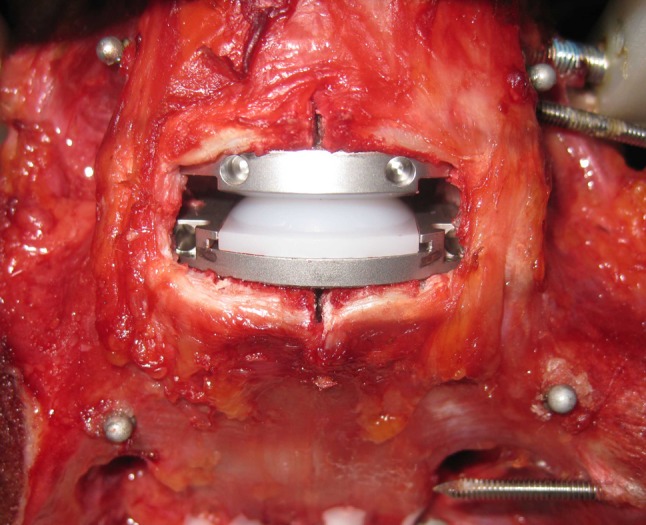
Anterior discectomy and insertion of ProDisc-L® artificial disc at the L5-S1 segment
Fig. 2.

Lateral plain radiographs showing the four prostheses: combinations at L5-S1 during testing: a 6°/0°, b 3°/3°, c 11°/0°, d 3°/8°
Data analysis
The motion data were analyzed to calculate: (1) L5-S1 ROM (FE, LB, AR) and (2) L5-S1 COR (FE) for different simulated conditions. Fluoroscopic images were obtained in neutral, full flexion and full extension postures and used to quantify L5-S1 COR location (in mm). COR was defined in a Cartesian coordinate system attached to the inferior vertebra with the origin located at the midpoint of the S1 superior endplate, the x-axis parallel to the superior endplate in the posterior–anterior direction, and the y-axis perpendicular to the endplate in the cranial–caudal direction. COR was calculated in collaboration with Medical Metrics Inc. (Houston, TX) using a two-frame analysis of fluoroscopic images corresponding to the maximum moment endpoints in extension and flexion. The measurement was performed on distortion-corrected images using a quantitative motion analysis (QMA) technique [8, 24].
The effect of lordosis distribution within the prosthesis on the lumbosacral kinematics (ROM and COR location) was analyzed using repeated-measures analysis of variance and post hoc tests with Bonferroni correction for multiple comparisons (Systat 10.2, Systat Software Inc., Richmond, CA). A power analysis was performed to determine if the sample sizes for the different groups were sufficient.
Results
Range of motion
Flexion–extension
The L5-S1 FE ROM was unaffected after insertion of a 6° lordosis prosthesis (n = 7). After implantation of prostheses with non-distributed lordosis angle under 400 N preload, FE ROM decreased from 8.9° ± 2.2° to 8.1° ± 2.8° (p = 0.613). Similarly, when the 6° of lordosis was distributed between the endplates (3°/3°), L5-S1 FE motion decreased compared to intact (7.0° ± 2.8°, p = 0.08) (Fig. 3).
Fig. 3.

Flexion–extension at 400 N preload range of motion at L5-S1. Intact values and after insertion of the Pro Disc L® device. Non-distributed design denotes either 6°/0° 11°/0° whereas distributed design denotes 3°/3° or 3°/8°
L5-S1 FE ROM was also unaffected after insertion of an 11° lordosis prosthesis (n = 5). When the 11°/0° design was inserted, the L5-S1 ROM was again decreased from 12.3° ± 3.5° to 11.4° ± 1.6° (p = 1.00). This change remained non-significant after the 3°/8° design was implanted (10.2° ± 1.1°, p = 0.68) (Fig. 3).
Lateral bending
Implants with 6° of lordosis yielded less LB motion than intact. Specifically, LB movements decreased from 5.4° ± 1.2° intact to 3.3° ± 1.5° with the 6°/0° design (p < 0.05) and further to 2.7° ± 1.4° with the 3°/3° design (p < 0.05) (Fig. 4).
Fig. 4.

Lateral bending range of motion at L5-S1. Intact values and after insertion of the Pro Disc L® device. Non-distributed design denotes either 6°/0° 11°/0° whereas distributed design denotes 3°/3° or 3°/8°
Prostheses with undistributed 11° lordosis decreased LB ROM from 6.8° ± 1.5° intact to 4.8° ± 1.5° after TDR (p = 0.07) and further to 4.2° ± 0.9° with the distributed 11° constructs (p < 0.05) (Fig. 4).
Axial rotation
When 6° lordosis prostheses were inserted, the 3°/3° design had significantly less AR motion than intact (2.6° ± 1.0° vs. 1.6° ± 0.8°, p < 0.05). Nevertheless, the reduction in AR motion was not significant when 6°/0° constructs were implanted (1.9° ± 0.9°, p = 0.06) (Fig. 5).
Fig. 5.

Axial rotation range of motion at L5-S1. Intact values and after insertion of the Pro Disc L® device. Non-distributed design denotes either 6°/0° 11°/0° whereas distributed design denotes 3°/3° or 3°/8°
In constructs with 11° of lordosis, the AR range of motion was not affected by distribution of lordosis as both designs yielded motion close to intact levels. AR ROM was reduced from 3.1° ± 1.5° intact with the 11°/0° design was reduced to 2.1° ± 1.4° (p = 0.20) and was further reduced to 1.8° ± 0.7° with the 3°/8° implant (p = 0.09) (Fig. 5).
Center of rotation
The mean intact COR was 4.3 ± 1.7 mm posterior to the anteroposterior (A–P) midline. In 6º implants, the mean COR was located 2.0 ± 1.4 mm posterior to the midline of the disc space in the 3°/3° design and 2.0 ± 1.6 mm posterior in the 6°/0° design. There was a trend for the COR location for either design to be more anterior than that of intact, but statistical significance was not reached (6°/0°: p = 0.07; 3°/3°: p = 0.12). In the cephalad–caudal axis, the mean intact COR was 2.7 ± 1.9 mm cephalad to the S1 superior endplate. For the 6°/0° design the COR was 1.5 ± 1.3 mm more caudal than intact (p = 0.15), whereas for the 3°/3° design the COR was 0.5 ± 1.4 mm more caudal than intact (p = 1.00) (Fig. 6).
Fig. 6.

The location of the center of rotation at L5-S1 during extension and flexion in the anteroposterior and cephalad–caudal axis. Intact values and after insertion of Pro Disc L® device with 6° of endplate lordosis. Old implant denotes 6°/0° and new implant denotes 3°/3°
In the 11° prostheses, the mean intact COR was 4.1 ± 1.7 mm posterior to the midline and 3.6 ± 1.0 mm cephalad to the S1 superior endplate. COR for the 3°/8° design was located 1.3 ± 1.7 mm more anterior and 1.1 ± 1.7 mm more caudal than intact (p = 0.67 and p = 0.80, respectively). COR for the 11°/0° design was 2.1 ± 2.2 mm more anterior (p = 0.40) and 2.4 ± 1.4 mm more caudal (p = 0.07) than intact (Fig. 7). The COR location of the 11°/0° design was more anterior and caudal than intact, but statistical significance was not reached (p > 0.05).
Fig. 7.

The location of the center of rotation at L5-S1 during extension and flexion in the anteroposterior and cephalad–caudal axis. Intact values and after insertion of Pro Disc L® device with 11° of endplate lordosis. Old implant denotes 11°/0° and new implant denotes 3°/8°
Power analysis
Power analyses were performed to determine if our sample sizes for the two study groups were sufficient to detect a mean difference of at least 30 % in range of motion. For the 6° implant combinations, a sample size of n = 7 results in a power of 99 % in flexion–extension and 79 % in lateral bending. For the 11° implant combinations, a sample size of n = 5 results in a power of 97 % in flexion–extension and 62 % in lateral bending. Power was low for axial rotation in both groups (49 % for the 6° implants; 22 % for the 11° implants).
Power analyses were also performed to detect a mean difference of 2 mm in the A–P and caudal–cephalad locations of the COR. For the 6° implant combinations, a sample size of n = 7 results in a power of 80 % in the A–P location of the COR, and 60 % in the caudal-cephalad location of the COR. For the 11° implant combinations, the corresponding power values were 35–50 % for the A–P locations, and 53–68 % for the caudal–cephalad locations.
Discussion
The present study tested the hypothesis that L5-S1 kinematics using prostheses with inherent lordosis distributed in both endplates will better approximate intact values when compared with prostheses with inherent lordosis distributed only in the upper endplate. FE ROM was not significantly influenced by the distribution of lordosis between prostheses endplates. With the exception of the undistributed 11° implant, LB movements were significantly reduced after artificial disc insertion. In all but the distributed 6° implant, AR remained unchanged after artificial disc insertion. The COR of the 6°/0° and 11°/0° implants were more anterior and more caudal than the corresponding intact locations. The COR of the distributed designs tended to be closer to the intact location.
This ex vivo study must be interpreted under the prism of some limitations. Biomechanical testing at best mimics the immediate post-operative condition and possible soft-tissue postoperative changes are not incorporated. In addition, ex vivo studies are unable to fully replicate the physiologic loads. The follower preload, used to simulate normal loads, was not applied during axial rotation and lateral bending due to limitations of the technique used to apply the follower preload [15, 16]. The use of bilateral cables to apply compressive follower preload during lateral bending and axial rotation tests is inappropriate for spine testing. This is due to the motion coupling between lateral bending and axial rotation and artifact moment in the plane of primary motion resulting from unequal preloads in the cables and the inability of the resultant preload vector to follow the moving COR. Furthermore, the a posteriori statistical analysis showed a low statistical power for the 11° lordosis group due to small sample size (n = 5). A larger sample size of 12–15 would be needed to obtain 80 % power.
In the current study, the initially inserted implant was removed and the other design (with distributed or non-distributed lordosis angles) was then implanted again at L5-S1. Removal of the initial implant and insertion of the second implant, in theory, could influence the kinematic behavior of the motion segment. However, precautions were taken and careful surgical technique was used to minimize the possible artifact of implant of reinsertion. Removal of the implants from the specimen was performed using specialized implant removal tools included in the implant set provided by the manufacturer. The second implant had the same footprint, insertion trajectory and anteroposterior position in the disc space as the first implant (this was confirmed with fluoroscopic imaging).
COR location is a clinically relevant measure of quality of motion. While 3-D motion data was collected using an optoelectronic motion measurement system, registration of the specimen anatomy was not performed. Therefore, COR was evaluated using fluoroscopic images, only in flexion–extension. We used images corresponding to endpoints of flexion–extension motion to ensure the maximum reliability of the COR data.
There is general agreement that, at least in the early postoperative period, after artificial disc insertion, the segmental lumbar kinematics approximate intact values [6]. Panjabi et al. [13] demonstrated in a cadaveric study that FE segmental motion was preserved, whereas LB and AR movements increased after disc arthroplasty using ProDisc with undistributed endplate lordosis angles at L5-S1. In the present study, FE ROM after ProDisc-L implantation approached intact values. Conversely, in most implant combinations, LB movements were significantly decreased. AR was not influenced by the implant insertion except in the case of the 3°/3° design which demonstrated significantly less motion than intact. Possible explanations for the reduced LB include the fixed COR within the ProDisc-L, tensioning of the anterolateral annulus during insertion, and increased lordosis after implantation resulting in increased facet joint contact [4, 5].
In ball-and-socket artificial disc designs such as the ProDisc-L, the COR of the reconstructed segment depends largely upon the location of the center of the ball and its radius of curvature [9]. It must be noted that the location of the COR differs among native spine levels, and that it changes during intervertebral motion [17]. At L5-S1, unlike other lumbar motion segments, the COR is located within the disc space [8, 9]. Rousseau et al. [18] reported that the locations of the COR in the L5-S1 segment after implantation of the ProDisc and Charité prostheses are not significantly influenced when the spines are tested in flexion–extension movements. In our study, the ProDisc-L prosthesis design where all lordosis is concentrated in the superior endplate yielded COR locations that were anterior and caudal to intact controls. The prosthesis with lordosis distributed between the two endplates yielded a COR that tended to be closer to intact. The COR was located more cranial with distributed endplate lordosis angles compared with non-distributed lordosis. This cranial shift in COR may be attributed to the increased thickness of the inferior endplate of the distributed lordosis angle prosthesis. The COR location has implications to the loading of the facet joints [18, 19]. High rates of facet joint pain have been reported after disc arthroplasty using Prodisc at L5-S1 [20]. This once again suggests that a mismatch between the axis of rotation of the ProDisc implanted segment with the facet anatomy of the native segment may lead to abnormal facet joint loading.
Distribution of segmental lordosis within the prosthesis may influence three-joint complex mechanics. Since COR location appears to be affected in the cranial–caudal direction by distribution of endplate lordosis, it is logical to expect that lordosis distribution may also influence facet loading. A COR more caudally located compared to the intact condition may increase the facet apposition in the reconstructed segment, whereas a more cranially located COR may cause increased capsular stretch [19]. Nonetheless, it is questionable how and whether this distribution will affect facet loading at the operated and adjacent segments, since factors such as implant position, pre-existing facet arthropathy, and facet joint gap dimensions may potentially influence the condition and viability of the facet joints. Further clinical and biomechanical studies are needed to assess the long-term impact of lordosis angle distribution on the fate of the facet joints.
We expected to see an effect of lordosis redistribution on the ROM of the implanted segment due to the expected movement of the COR caused by the redistribution of lordosis. However, the fact that the change in ROM was not significant may have multifactorial explanations. In our opinion, the most likely explanation is the fact that the effect on ROM caused by the small magnitude of COR movement may have been masked by the variability in COR location of the intact segments as shown in Figs. 6 and 7.
In L5-S1 total disc arthroplasty, it is unclear whether prostheses should have the endplate lordosis angle incorporated in only the upper, only the lower, or distributed within both prosthesis endplates. Moreover, when a distributed endplate lordosis angle design is implanted, it remains controversial whether the overall angle should be equally distributed in the construct components. Of note, we were able to test this only for the 3°/3° device. Only carefully designed and executed clinical studies can provide answers to the above questions.
Theoretically, the distribution of lordosis in both endplates will better simulate native disc geometry and lumbosacral lordosis, therefore better mimicking natural biomechanics and the spinopelvic parameters necessary for maintaining sagittal balance. The importance of maintaining sagittal balance for good long-term clinical outcome has been well documented in the literature. Le Huec et al. and Tournier et al. [10, 22] demonstrated that total disc replacement using three different types of lumbar disc prostheses allowed maintenance of good sagittal balance. The present study did not address the issue of sagittal balance per se and only investigated the effect of distribution of lordosis angle between prosthesis endplates.
Conclusion
Overall, L5-S1 range of motion was not markedly influenced by lordosis distribution among the two prosthesis endplates. The ProDisc-L prosthesis design where all lordosis is concentrated in the superior endplate yielded COR locations that were anterior and caudal to intact controls. The prosthesis with lordosis distributed between the two endplates yielded a COR that tended to be closer to intact. Further clinical and biomechanical studies are needed to assess the long-term impact of lordosis angle distribution on the fate of the facet joints.
Acknowledgments
This study was supported by funds provided by the Department of Veterans Affairs, Washington, D.C. and Synthes Spine, West Chester, PA.
Conflict of interest
None.
References
- 1.Anderson PA, Rouleau JP. Intervertebral disc arthroplasty. Spine (Phila Pa 1976) 2004;29:2779–2786. doi: 10.1097/01.brs.0000146460.11591.8a. [DOI] [PubMed] [Google Scholar]
- 2.Bertagnoli R, Kumar S. Indications for full prosthetic disc arthroplasty: a correlation of clinical outcome against a variety of indications. Eur Spine J. 2002;11(Suppl 2):S131–S136. doi: 10.1007/s00586-002-0428-4. [DOI] [PMC free article] [PubMed] [Google Scholar]
- 3.Delamarter R, Pradhan B. ProDisc-L total disc replacement. In: Yue J, Bertagnoli R, McAfee PC, An HS, editors. Motion preservation surgery of the spine. Philadelphia: Saunders Elsevier; 2008. pp. 318–325. [Google Scholar]
- 4.Demetropoulos CK, Sengupta DK, Knaub MA, Wiater BP, Abjornson C, Truumees E, Herkowitz HN. Biomechanical evaluation of the kinematics of the cadaver lumbar spine following disc replacement with the ProDisc-L prosthesis. Spine (Phila Pa 1976) 2010;35:26–31. doi: 10.1097/BRS.0b013e3181c4eb9a. [DOI] [PubMed] [Google Scholar]
- 5.Gaffey JL, Ghanayem AJ, Voronov ML, Havey RM, Carandang G, Abjornson C, Patwardhan AG. Effect of increasing implant height on lumbar spine kinematics and foraminal size using the ProDisc-L prosthesis. Spine (Phila Pa 1976) 2010;35:1777–1782. doi: 10.1097/BRS.0b013e3181ebaa4d. [DOI] [PubMed] [Google Scholar]
- 6.Galbusera F, Bellini CM, Zweig T, Ferguson S, Raimondi MT, Lamartina C, Brayda-Bruno M, Fornari M. Design concepts in lumbar total disc arthroplasty. Eur Spine J. 2008;17:1635–1650. doi: 10.1007/s00586-008-0811-x. [DOI] [PMC free article] [PubMed] [Google Scholar]
- 7.Gilad I, Nissan M. Sagittal evaluation of elemental geometrical dimensions of human vertebrae. J Anat. 1985;143:115–120. [PMC free article] [PubMed] [Google Scholar]
- 8.Hipp JA, Wharton ND. Quantitative motion analysis (QMA) of motion-preserving and fusion technologies for the spine. In: Yue JJ, Bertagnoli R, McAfee PC, An HS, editors. Motion preservation surgery of the spine. Philadelphia: Saunders Elsevier; 2008. pp. 85–96. [Google Scholar]
- 9.Huang RC, Wright TM, Panjabi MM, Lipman JD. Biomechanics of nonfusion implants. Orthop Clin North Am. 2005;36:271–280. doi: 10.1016/j.ocl.2005.02.010. [DOI] [PubMed] [Google Scholar]
- 10.Huec J, Basso Y, Mathews H, Mehbod A, Aunoble S, Friesem T, Zdeblick T. The effect of single-level, total disc arthroplasty on sagittal balance parameters: a prospective study. Eur Spine J. 2005;14:480–486. doi: 10.1007/s00586-004-0843-9. [DOI] [PMC free article] [PubMed] [Google Scholar]
- 11.Mayer HM. Total lumbar disc replacement. J Bone Joint Surg Br. 2005;87:1029–1037. doi: 10.1302/0301-620X.87B8.16151. [DOI] [PubMed] [Google Scholar]
- 12.McKenzie AH. The basis for motion preservation surgery: lessons learned from the past. In: Yue JJ, Bertagnoli R, McAfee PC, An HS, editors. Motion preservation surgery of the spine. Philadelphia: Saunders Elsevier; 2008. [Google Scholar]
- 13.Panjabi M, Henderson G, Abjornson C, Yue J. Multidirectional testing of one- and two-level ProDisc-L versus simulated fusions. Spine (Phila Pa 1976) 2007;32:1311–1319. doi: 10.1097/BRS.0b013e318059af6f. [DOI] [PubMed] [Google Scholar]
- 14.Patwardhan AG, Havey RM, Carandang G, Simonds J, Voronov LI, Ghanayem AJ, Meade KP, Gavin TM, Paxinos O. Effect of compressive follower preload on the flexion-extension response of the human lumbar spine. J Orthop Res. 2003;21:540–546. doi: 10.1016/S0736-0266(02)00202-4. [DOI] [PubMed] [Google Scholar]
- 15.Patwardhan AG, Havey RM, Meade KP, Lee B, Dunlap B. A follower load increases the load-carrying capacity of the lumbar spine in compression. Spine (Phila Pa 1976) 1999;24:1003–1009. doi: 10.1097/00007632-199905150-00014. [DOI] [PubMed] [Google Scholar]
- 16.Patwardhan AG, Meade KP, Lee B. A frontal plane model of the lumbar spine subjected to a follower load: implications for the role of muscles. J Biomech Eng. 2001;123:212–217. doi: 10.1115/1.1372699. [DOI] [PubMed] [Google Scholar]
- 17.Pearcy MJ, Bogduk N. Instantaneous axes of rotation of the lumbar intervertebral joints. Spine (Phila Pa 1976) 1988;13:1033–1041. doi: 10.1097/00007632-198809000-00011. [DOI] [PubMed] [Google Scholar]
- 18.Rousseau MA, Bradford DS, Bertagnoli R, Hu SS, Lotz JC. Disc arthroplasty design influences intervertebral kinematics and facet forces. Spine J. 2006;6:258–266. doi: 10.1016/j.spinee.2005.07.004. [DOI] [PubMed] [Google Scholar]
- 19.Sears WR, McCombe PF, Sasso RC. Kinematics of cervical and lumbar total disc replacement. Semin Spine Surg. 2006;18:117–129. doi: 10.1053/j.semss.2006.03.013. [DOI] [Google Scholar]
- 20.Siepe CJ, Korge A, Grochulla F, Mehren C, Mayer HM. Analysis of post-operative pain patterns following total lumbar disc replacement: results from fluoroscopically guided spine infiltrations. Eur Spine J. 2008;17:44–56. doi: 10.1007/s00586-007-0519-3. [DOI] [PMC free article] [PubMed] [Google Scholar]
- 21.Szpalski M, Gunzburg R, Mayer M. Spine arthroplasty: a historical review. Eur Spine J. 2002;11(Suppl 2):S65–S84. doi: 10.1007/s00586-002-0474-y. [DOI] [PMC free article] [PubMed] [Google Scholar]
- 22.Tournier C, Aunoble S, Huec JC, Lemaire JP, Tropiano P, Lafage V, Skalli W. Total disc arthroplasty: consequences for sagittal balance and lumbar spine movement. Eur Spine J. 2007;16:411–421. doi: 10.1007/s00586-006-0208-7. [DOI] [PMC free article] [PubMed] [Google Scholar]
- 23.Yue JJ, Oetgen ME, Torre JJJ, Bertagnoli R. Does vertebral endplate morphology influence outcomes in lumbar disc arthroplasty? Part I: an initial assessment of a novel classification system of lumbar endplate morphology. SAS Journal. 2008;2:16–22. doi: 10.1016/S1935-9810(08)70013-6. [DOI] [PMC free article] [PubMed] [Google Scholar]
- 24.Zhao K, Yang C, Zhao C, An KN. Assessment of non-invasive intervertebral motion measurements in the lumbar spine. J Biomech. 2005;38:1943–1946. doi: 10.1016/j.jbiomech.2004.07.029. [DOI] [PubMed] [Google Scholar]