Abstract
This study tested the hypotheses that (1) cervical total disc replacement with a compressible, six-degree-of-freedom prosthesis would allow restoration of physiologic range and quality of motion, and (2) the kinematic response would not be adversely affected by variability in prosthesis position in the sagittal plane. Twelve human cadaveric cervical spines were tested. Prostheses were implanted at C5–C6. Range of motion (ROM) was measured in flexion–extension, lateral bending, and axial rotation under ±1.5 Nm moments. Motion coupling between axial rotation and lateral bending was calculated. Stiffness in the high flexibility zone was evaluated in all three testing modes, while the center of rotation (COR) was calculated using digital video fluoroscopic images in flexion–extension. Implantation in the middle position increased ROM in flexion–extension from 13.5 ± 2.3 to 15.7 ± 3.0° (p < 0.05), decreased axial rotation from 9.9 ± 1.7 to 8.3 ± 1.6° (p < 0.05), and decreased lateral bending from 8.0 ± 2.1 to 4.5 ± 1.1° (p < 0.05). Coupled lateral bending decreased from 0.62 ± 0.16 to 0.39 ± 0.15° for each degree of axial rotation (p < 0.05). Flexion–extension stiffness of the reconstructed segment with the prosthesis in the middle position did not deviate significantly from intact controls, whereas the lateral bending and axial rotation stiffness values were significantly larger than intact. Implanting the prosthesis in the posterior position as compared to the middle position did not significantly affect the ROM, motion coupling, or stiffness of the reconstructed segment; however, the COR location better approximated intact controls with the prosthesis midline located within ±1 mm of the disc-space midline. Overall, the kinematic response after reconstruction with the compressible, six-degree-of-freedom prosthesis within ±1 mm of the disc-space midline approximated the intact response in flexion–extension. Clinical studies are needed to understand and interpret the effects of limited restoration of lateral bending and axial rotation motions and motion coupling on clinical outcome.
Keywords: Cervical spine, Total disc replacement, Biomechanics, Motion coupling, Center of rotation
Introduction
Activities of daily living (ADL) require the sub-axial cervical spine to have substantial mobility in flexion–extension, lateral bending, and axial rotation [21, 23, 33]. These segments also demonstrate a characteristic coupling between lateral bending and axial rotation, dictated by the orientation of the articular facet surfaces and the uncinate processes [3, 13, 16, 23, 33, 35, 37, 39, 51, 58]. Degenerative disc disease in the cervical spine can cause abnormal motions and altered load distribution within the disc, leading to discogenic pain and severely limiting the ability of individuals to perform ADL.
Historically, anterior cervical discectomy and fusion (ACDF) has been widely used to treat symptomatic cervical spondylosis [7]. Clinical studies suggest that cervical fusion predisposes the remaining mobile segments to degeneration [1, 18, 19, 22, 55]. Biomechanical studies have reported increased motion and stresses in adjacent segments after fusion, which are thought to accelerate their degeneration [9, 15]. More recently, total disc replacement (TDR) has been recommended as an alternative to ACDF [4, 12, 26, 30, 43, 55]. TDR has been clinically used for the treatment of radiculopathy and myelopathy, aiming at replicating the natural motions of the treated level [24, 53]. The proposed advantages of TDR are based on the premise that preservation of physiologic mechanics would lead to longevity of the facet joints at the index level and mitigate the risk of adjacent segment disease evidenced after fusion, thereby reducing the need for additional surgery [24, 53].
Artificial cervical disc prostheses of various designs have been developed in recent years. The prostheses fall into four design categories: single spherical bearing, saddle joint, mobile core with two bearings, and non-articulating [49]. The ability to restore physiologic motion to the implanted cervical spine segment likely depends on multiple factors, including the nature of articulation that determines the kinematic degrees of freedom of the disc prosthesis. A non-articulating prosthesis with a compressible core offers six kinematic degrees of freedom, and therefore, has the potential to approximate the axes of rotation of the native segment in flexion–extension, lateral bending, and axial rotation.
The purpose of this study was to test the following hypotheses: (1) total disc replacement using a compressible, six-degree-of-freedom cervical disc prosthesis would allow restoration of physiologic range of motion (ROM) and quality of motion (motion coupling, stiffness, and center of rotation) to near normal values, and (2) the kinematic response of the implanted segment would not be adversely affected by variability in prosthesis position in the sagittal plane.
Materials and methods
M6 cervical disc prosthesis
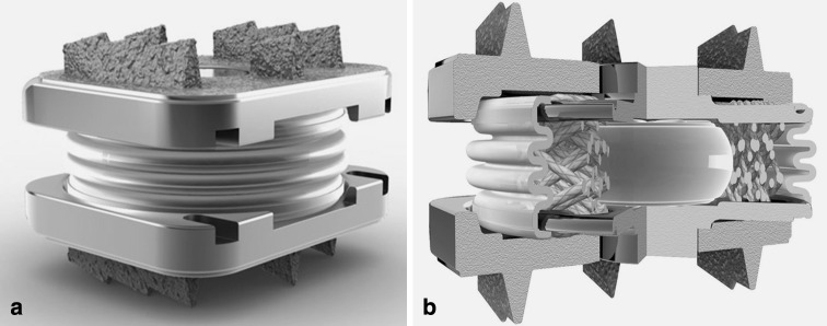
The hypotheses were tested using the M6® cervical disc prosthesis (Spinal Kinetics, Sunnyvale, CA) (henceforth, M6), which is a non-articulating disc prosthesis allowing six kinematic degrees of freedom and graded resistance to motion. The prosthesis design incorporates a polymer core to allow axial compression and a woven fiber annulus for achieving controlled range of motion in all planes (Fig. 1). The fiber annulus is wound through Titanium alloy inner endplates, which are ultimately laser-welded to the outer endplates. The outer endplates have a tri-keel design for acute fixation and are coated with Titanium Plasma Spray for osseous integration [46].
Fig. 1.
The M6® cervical disc prosthesis: a assembled device and b cross-sectional view
Specimens and experimental set-up
Twelve human cadaveric cervical spine specimens (C3–C7) were used (age 50.8 ± 4.8 years; range 42–56 years; 6 males, 6 females). The specimens had no radiographic signs of metastatic disease or bridging osteophytes and no evidence of listhesis on anteroposterior and lateral digital fluoroscopy images. The paravertebral muscles were dissected while keeping the discs, ligaments, and posterior bony structures intact. The specimens were wrapped in saline-soaked towels to prevent tissue dehydration. All tests were performed at room temperature.
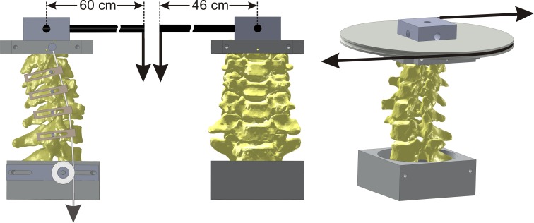
The C3 and C7 vertebrae were anchored in cups using bone cement and pins. The specimen was fixed to the apparatus at the caudal end (C7) while the motion of the C3 vertebra was unconstrained. A moment was applied by controlling the flow of water into bags attached to loading arms fixed to the C3 vertebra (Fig. 2). No counter-balance was used during flexion–extension and lateral bending tests. The loading mechanism consisted of a carbon fiber rod that extended 60 cm from the point of attachment on C3 for flexion–extension test and 46 cm for lateral bending test. Due to the long moment arms, the compressive load corresponding to the moment magnitude of 1.5 Nm was approximately 2.7 N in flexion–extension and 3.3 N in lateral bending. The off-axis moments during these tests were on average less than 0.1 Nm. The test in axial rotation was performed using a pure axial rotation moment. The apparatus allowed continuous cycling of the specimen between specified maximum moment endpoints in flexion, extension, lateral bending, and axial rotation.
Fig. 2.
Schematic of the loading apparatus for flexibility tests in flexion–extension, lateral bending, and axial rotation
The three-dimensional motions of the C3, C4, C5, and C6 vertebrae relative to C7 were measured using an optoelectronic motion measurement system (Model 3020, Optotrak®, Northern Digital, Waterloo, ON, Canada). In addition, bi-axial angle sensors (Model 902-45, Applied Geomechanics, Santa Cruz, CA, USA) were mounted on each vertebra to allow real-time feedback for the optimization of the preload path. A six-component load cell (Model MC3A-6-1000, AMTI Multi-component transducers, AMTI Inc., Newton, MA, USA) was placed under the specimen to measure the applied compressive preload and moments. Intervertebral motions as well as implant motions during flexion and extension were also monitored using sequential digital fluoroscopic images obtained over the full range of flexion–extension motion (OEC 9800 Plus, GE OEC Medical Systems, Inc., UT).
Compressive preload was applied to the specimen during the flexion–extension test using the follower load technique described by Patwardhan et al. [41]. The cables were attached to the cup holding C3 vertebra, passed freely through guides anchored to each vertebra and were connected to a loading hanger under the specimen [52]. The cable guide mounts allowed anterior-posterior adjustments of the follower load path. The preload path was optimized by adjusting the cable guides to minimize changes in cervical lordosis when a compressive load of up to 150 N was applied to the specimen. Real-time feedback of segmental lordosis change was obtained from the bi-axial angle sensors mounted on each vertebral body. The preload path was considered optimized when a segmental lordosis change of less than ±0.3° was obtained at the index level, and the total lordosis change (C3–C7) was less than ±1.0° when the preload was increased from 0 to 150 N. Patwardhan et al. [40] previously demonstrated that application of a compressive load along an optimized follower load path minimizes the segmental bending moments and shear forces due to the preload application, thereby allowing the spine to support a 150 N compressive preload without damage or instability [41].
Experimental protocol
Prior to intact testing, the preload path was optimized using the technique described above. Similarly, the optimization of the preload path was checked before formal testing began after implantation of the disc prosthesis. If the change in segmental lordosis during preload application exceeded ±0.3°, the preload path was re-optimized. Once optimized for a given testing sequence, no further alterations were made to the load path during testing.
Each specimen was tested in random order under the following loads: (1) flexion–extension (±1.5 Nm) with a compressive preload of 150 N, (2) lateral bending (±1.5 Nm) without compressive preload (0 N), and (3) axial rotation (±1.5 Nm) without compressive preload (0 N). The load–displacement data were acquired until two reproducible load–displacement loops were obtained, generally requiring a maximum of three loading cycles.
Operative technique
The operative technique used in this study followed the manufacturer’s guidelines on surgical technique. After testing the intact spine, a C5–C6 discectomy was performed using standard instruments. An anterior window was made in the annulus wide enough to accommodate the prosthesis width (as opposed to complete wide discectomy) (Fig. 3), resulting in the maintenance of the anterolateral annular fibers to serve as a tension band in providing stability in extension after TDR. The vertebral endplates were scraped clean, while preserving their structural integrity. The posterior longitudinal ligament (PLL) was transected for all implanted segments based on our prior experience that removal of the PLL facilitates more parallel disc space distraction and proper placement of the prosthesis. Trial sizing with the help of fluoroscopy was performed to select the prosthesis footprint that maximized the endplate coverage without removing the uncinate processes. The appropriate prosthesis height was selected based on the tightness of the fit, the preoperative middle intervertebral height at the index level, and the heights of the unaffected adjacent levels. This followed the manufacturer’s guidelines for the operative technique for the M6 cervical disc prosthesis [46] and was consistent with the technique described for other cervical disc prostheses [5, 8, 29].
Fig. 3.
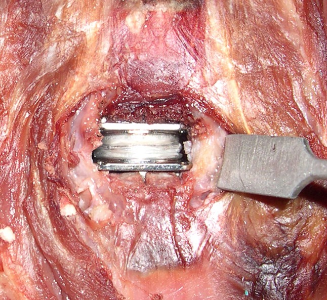
Intraoperative image: M6 artificial disc implantation at C5–C6
Prior to the implantation of the prosthesis, keel tracks were created under fluoroscopic guidance to the full A-P width of the superior and inferior vertebral bodies and centered in the disc space in the frontal plane using surgical instruments provided by the manufacturer [46]. An inserter was used to insert the implant in the prepared disc space. Initially, the prosthesis midline was positioned within ±1 mm of the midline of the disc space in the mid-sagittal plane (middle position) under fluoroscopic guidance. Following implantation of the prosthesis, the specimen was tested in flexion–extension, lateral bending, and axial rotation as described above.
The effect of surgical variability in prosthesis position in the sagittal plane on the kinematics of the implanted segment was investigated in six specimens. After testing the prosthesis in the middle position, the implant inserter was used to position the prosthesis further posterior under fluoroscopic guidance without encroaching the canal (posterior placement). This step did not create additional damage to the endplates. This was visually confirmed and documented after disarticulating the implanted segment at the end of the experiment. None of the specimens demonstrated any damage to their endplates.
Data analysis
Disc height and prosthesis position
The mid-disc height was measured on the lateral digital fluoroscopic images of the intact spines. It was not possible to reliably measure the disc height after implantation since the prosthesis obscured a clear definition and visualization of the C6 superior endplate. The implant position in the disc space was measured in both the middle and posterior positions. The position was assessed in terms of the midline of the prosthesis in relation to the midline of the disc space on the lateral digital fluoroscopic images. All measurements were performed by three investigators using an image analysis software (Image-Pro Plus, version 4.1.0.0 for Windows, Media Cybernetics, Bethesda, MD, USA). Excellent inter-observer reliability among the three observers was noted for both the disc height and implant position (Cronback’s α = 0.97 for both). Therefore, measurements performed by the three observers were averaged to obtain the mean disc height and implant position.
Range of motion and motion coupling
The load–displacement data were analyzed to determine the flexion–extension, lateral bending, and axial rotation angular range of motion (ROM) at C5–C6 before and after TDR. Motion coupling between axial rotation and lateral bending was analyzed using linear regression analysis of the data collected from the axial rotation test. This was performed separately on the coupled lateral bending noted with right axial rotation and on the coupled lateral bending with left axial rotation.
Stiffness in the high flexibility zone
Load–displacement curves of the C5–C6 segment in flexion–extension, lateral bending, and axial rotation were analyzed to measure the stiffness of the motion segment in its high flexibility zone before and after TDR. The C5–C6 segmental stiffness (Nm/degree) was calculated using the slope of the linear portion of the load–displacement curve in the high flexibility region around the neutral posture [40].
Center of rotation for flexion–extension motion
The location of the center of rotation (COR) of the C5–C6 segment in flexion–extension was quantified using digital fluoroscopic images. The location of the COR was defined in a Cartesian coordinate system attached to the inferior vertebra. The origin was located at the midpoint of the superior endplate of the C6 vertebra, with the x-axis parallel to the superior endplate in the postero-anterior direction and the y-axis perpendicular to the endplate in the cranial–caudal direction. The COR was calculated using a two-frame analysis of full extension and full flexion fluoroscopic images, corresponding to ±1.5 Nm moments. The COR measurements were produced in collaboration with Medical Metrics Inc. (Houston, TX, USA) by analyzing distortion-corrected images using a quantitative motion analysis (QMA®) technique [20]. COR was calculated in units of millimeters.
Reliability of COR calculations
Three analysts experienced with the use of the QMA® technology each tracked flexion–extension digital fluoroscopic images of 12 intact human cadaveric cervical spines. Each analyst tracked every case twice. The cases were given a random code during each trial, such that the analysts did not have access to their previous results or any of the results of the other analysts. QMA® was used to calculate a set of measurements that included intervertebral rotation and the anterior–posterior and cranial–caudal coordinates of the COR. Intervertebral rotation and COR were calculated for intervertebral motion from full extension to full flexion. Between 2 and 3 levels were tracked in each spine. The QMA data were decoded and provided for statistical analysis after all of the tracking was completed. Inter- and intra-observer agreement was measured using Lin’s concordance coefficients as well as a Bland–Altman [2] analysis. Intra-observer agreement was calculated using data from both trials made by each analyst. Inter-observer agreement was calculated between analysts 1 and 2, analysts 1 and 3, and analysts 2 and 3.
Statistical analysis
The ROM, stiffness, location of the COR, and motion coupling coefficients were analyzed using a repeated-measures analysis of variance. Post-hoc tests were performed, and Bonferroni correction was applied to account for multiple comparisons. The level of significance was set as two-tailed α equal to 0.05.
Results
Implant sizes and position in the disc space
A total of 12 human cadaveric cervical spines were operated at the C5–C6 level. Based on the criteria described in the operative technique, M6 disc prostheses of 7 mm height were implanted in seven specimens, whereas a 6-mm M6 disc was implanted in five specimens (Table 1). In 11 specimens, a medium footprint size implant was chosen, but in one specimen a large footprint size prosthesis was considered appropriate.
Table 1.
Specimen demographics, native disc heights, and disc prostheses sizes
| Specimen | Age (years) | Sex | Native disc height at C5–C6 (mm) | Implant at C5–C6 height/footprint |
|---|---|---|---|---|
| 1 | 55 | M | 6.5 | 7 mm/large |
| 2 | 57 | M | 5.0 | 7 mm/medium |
| 3 | 55 | F | 6.7 | 7 mm/medium |
| 4 | 42 | F | 5.8 | 6 mm/medium |
| 5 | 49 | F | 6.5 | 7 mm/medium |
| 6 | 55 | F | 4.7 | 6 mm/medium |
| 7 | 46 | M | 7.2 | 7 mm/medium |
| 8 | 56 | F | 4.8 | 6 mm/medium |
| 9 | 48 | M | 5.9 | 7 mm/medium |
| 10 | 55 | F | 6.2 | 6 mm/medium |
| 11 | 47 | M | 7.0 | 6 mm/medium |
| 12 | 48 | M | 6.5 | 7 mm/medium |
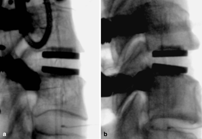
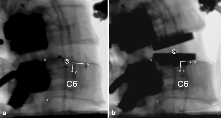
The middle implantation position resulted in the prosthesis midline to be 0.1 ± 0.6 mm posterior to the midline of the disc space in the sagittal plane (range: 1.2 mm anterior to 0.9 mm posterior). In the posterior implantation position, the prosthesis midline was 1.8 ± 0.1 mm posterior to the midline of the disc space (range 1.6–1.9 mm posterior). The difference between the middle and posterior implantation positions was 2.2 ± 0.4 mm (range 1.8–2.8 mm) (p < 0.05) (Fig. 4).
Fig. 4.
Lateral fluoroscopic image after M6 insertion: a middle placement and b posterior placement
Range of motion
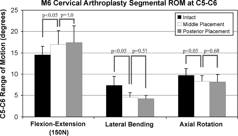
Positioning the prosthesis at or near the midline of the C5–C6 disc space in the sagittal plane increased ROM in flexion–extension from 13.5 ± 2.3° in the intact segment to 15.7 ± 3.0° in the implanted segment (p < 0.05), decreased axial rotation from 9.9 ± 1.7 to 8.3 ± 1.6° (p < 0.05), and decreased lateral bending from 8.0 ± 2.1 to 4.5 ± 1.1° (p < 0.05). The ROM values of the reconstructed segment with the prosthesis in the posterior position were not significantly different from the values for the middle position of the prosthesis in flexion–extension (p = 1.0), lateral bending (p = 0.51), and axial rotation (p = 0.68) (Fig. 5).
Fig. 5.
Segmental range of motion at C5–C6 in intact specimens, after middle placement, and after posterior placement
Motion coupling
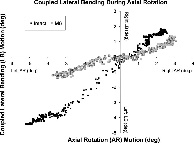
The relationship between axial rotation and coupled lateral bending motions was linear (R2 = 0.87 ± 0.12) for intact and reconstructed specimens (Fig. 6). The slope of the linear relationship (degrees of coupled lateral bending motion per degree of axial rotation) was 0.62 ± 0.16 for the intact C5–C6 segment. After implantation of the disc prosthesis in the middle position, the slope decreased to 0.39 ± 0.15° (p < 0.05), indicating a significant decrease in the coupled lateral bending motion for each degree of angular motion in axial rotation. Variability in prosthesis positioning in the disc space did not significantly affect the relationship between axial rotation and coupled lateral bending (p = 0.36).
Fig. 6.
Motion coupling between axial rotation and lateral bending for the C5–C6 segment: intact segment and after disc replacement using the M6 disc prosthesis
Stiffness in the high flexibility zone
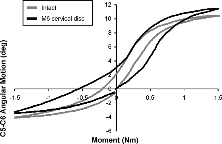
The load–displacement curve pattern in flexion–extension after TDR was sigmoidal, and approximated intact controls under a 150 N compressive preload (Fig. 7). With the prosthesis in the middle position, the stiffness of the reconstructed segment in the high flexibility zone in flexion–extension was not significantly different from that of intact segments (p = 0.38) (Table 2). The stiffness of the reconstructed segment with the prosthesis in the posterior position was not significantly different from the value for the middle position of the prosthesis (p = 1.0), but it was significantly smaller than the value for the intact segment (p < 0.05).
Fig. 7.
Load–displacement curves in flexion–extension under 150 N preload
Table 2.
Segmental (C5–C6) stiffness (Nm/degree) in the high flexibility zone
| Loading mode | Intact segment | Prosthesis position | |
|---|---|---|---|
| Middle | Posterior | ||
| Flexion–extension | 0.09 ± 0.04 | 0.07 ± 0.03 | 0.06 ± 0.02* |
| Lateral bending | 0.14 ± 0.14 | 0.52 ± 0.18† | 0.52 ± 0.16† |
| Axial rotation | 0.08 ± 0.05 | 0.20 ± 0.08† | 0.17 ± 0.04† |
*Significantly smaller value than intact (p < 0.05)
†Significantly larger value than intact (p < 0.05)
In both lateral bending and axial rotation, the stiffness values for the reconstructed segment with the prosthesis in the middle position were significantly larger than the values for the intact segment (Table 2) (p < 0.05), but they were not significantly affected by implanting the prosthesis in the posterior position (p = 1.0 and p = 0.24, respectively).
Center of rotation
Reliability of COR measurements
There was very high (>0.82) Lin’s concordance correlation between analysts for all of the measurements. The range in concordance was 0.99–0.995 for intervertebral rotation, 0.82–0.86 for the AP coordinate of the COR, and 0.88–0.89 for the cranial–caudal coordinate of the COR. The 95% confidence intervals for the Bland–Altman limits of agreement (LOA) suggest that the LOA for the QMA analysts were ±0.9 mm for the A-P coordinate of the COR and ±1.5 mm for the cranial–caudal coordinate of the COR. The minimum intervertebral rotation was 4.2° with a mean of 13.0° (±3.1°). For each of the COR measurements, the average of the six measurements (3 analysts × 2 trials) was calculated and assumed to be the best estimate of the true value. The error in each individual measurement was then calculated relative to the “best-estimate”. The average error for all variables was zero, and the histograms showed approximately normally distributed data. The magnitude of the error in the COR was significantly (p < 0.01) related to the amount of intervertebral rotation. Analysis of COR is considered meaningful only in the presence of significant intervertebral rotation. The minimum intervertebral rotation in this study was 4.2°, which is an amount of rotation that allows for reliable assessment of COR.
These data help with interpretation of results for individual specimens tested in the present study. The errors were normally distributed, so if statistical tests show a difference between the treatment groups, then this difference can be considered “real” even if the magnitude of the difference is less than the limits of agreement determined from this observer agreement study.
COR for the intact and reconstructed segments
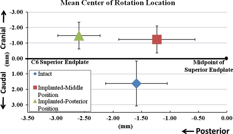
In the intact C5–C6 segment, the COR for total motion from maximum extension to maximum flexion was located 1.6 ± 0.5 mm posterior to the midpoint of C6 superior endplate and 1.6 ± 1.5 mm caudal to the C6 superior endplate. Implanting the prosthesis in the middle position in the sagittal plane did not significantly shift the location of the COR in the anterior or posterior direction as compared to the intact controls (p = 0.58) (Figs. 8, 9). However, the COR location was more cranial in the implanted segment as compared to the intact control by 2.9 ± 1.3 mm (p < 0.05).
Fig. 8.
Location of COR at C5–C6 segment for total motion from full extension to full flexion: a intact segment and b implanted segment. The COR is shown on the full extension frame for each case
Fig. 9.
Effect of prosthesis position on the location of the COR
Variability in prosthesis positioning in the disc space significantly affected the location of the COR. Posterior positioning moved the COR 1.7 ± 0.5 mm further posterior (p < 0.05) as compared to its location when the prosthesis was implanted in the middle position. The COR of the implanted segment with posterior positioning of the disc prosthesis was also 1.1 ± 0.6 mm more posterior (p = 0.05) and 2.9 ± 0.9 mm more cranial (p < 0.05) as compared to its location in intact segments.
Discussion
Total disc replacement at the C5–C6 segment with the M6 prosthesis maintained the flexion–extension motion at or slightly above the intact values. For the flexion–extension motion, the kinematic signature (load vs. angular displacement curve pattern), stiffness, and A-P location of COR did not deviate significantly from the intact controls after implanting the prosthesis in the middle position. The ROM of the reconstructed segment was not significantly affected by variability in prosthesis positioning in the sagittal plane, whereas the COR location was significantly more posterior as compared to its location in intact controls when the prosthesis was implanted in the posterior position. The COR location was more cranial compared to its intact location in both the middle and posterior positions of the prosthesis. The ROM in axial rotation and lateral bending, and motion coupling decreased compared to the intact controls. The corresponding stiffness values of the reconstructed segment in the high flexibility zone significantly increased compared to the intact values. The variability in prosthesis positioning (middle vs. posterior) did not significantly influence the ROM and stiffness in lateral bending and axial rotation.
The kinematic response of the M6 cervical disc prosthesis was evaluated using human cadaveric cervical spines in a load-control experiment [56]. We selected the ±1.5 Nm moment magnitude based on our previous experience in evaluating the kinematics of motion preserving implants for the cervical spine [27, 28, 42, 52]. The moment values used in previous studies for flexibility testing of cervical spine specimens have ranged from 1.0 to 5 Nm [10, 17, 25, 38, 45, 47, 48]. Indeed, Panjabi et al. [37] opined that a maximum moment value of 1.0 Nm is sufficient to produce physiologic motions without injuring the spine. The above argument is further supported by a comparison of the ROM data from the present study that utilized a moment of 1.5 Nm to the ROM reported in published studies on human cadaveric cervical spines using maximum moment values ranging from 1.0 to 5.0 Nm. While a direct comparison among different studies is difficult due to differences in specimen quality, the ROM data from the present study is very comparable to the reported range of ROM values. Further, stressing the motion segment beyond 1.5 Nm over multiple tests increases the risk of soft tissue degradation and precludes comparison to intact data.
The motion response of the intact and reconstructed cervical spine in flexion–extension was evaluated under 150 N compressive follower preload. The 150 N compressive preload represents the compressive preload that results from the dynamic stabilizing action of muscles in balancing the weight of the head over the cervical spine. Moroney et al. [34] estimated in vivo compressive loads on the cervical spine and found values ranging from 122 N in a relaxed posture to just over 1,100 N in activities that require increased muscle exertions.
The follower preload was not applied during axial rotation and lateral bending tests due to limitations of the bilateral cable technique used to apply the follower preload. The use of bilateral cables to apply compressive follower preload during lateral bending and axial rotation tests is inappropriate for cervical spine testing due to the motion coupling between lateral bending and axial rotation. The bilateral cables have the potential to introduce artifact moments during lateral bending for two reasons. First, the preloads in the two cables may not remain equal due to friction in the bilateral cable guides, resulting in an artifact moment in the plane of the primary motion (unlike in flexion–extension where the bilateral cables are in the coronal plane). Second, an internal artifact moment can arise due to an inability of the resultant preload vector to follow the moving COR in lateral bending and, unlike in flexion–extension, the cable path cannot be optimized to reduce the internal artifact moment. In axial rotation, the bilateral preload cables would apply a counter torque, thereby artificially stiffening the segment. Due to the motion coupling present in the cervical spine, these factors together can introduce substantial artifact moments and lead to erroneous results in lateral bending and axial rotation when tested with bilateral follower preload cables.
A number of in vivo studies have measured segmental motions of the sub-axial (C2–C7) cervical spine in healthy asymptomatic human subjects [21, 23, 33]. The average range of motion in flexion–extension at C5–C6 was 15.6 ± 4.9° based on a study of 50 healthy subjects [21]. The average one-sided lateral bending motion at C5–C6 was 4.3 ± 1.4° in 12 subjects, and the average one-sided axial rotation motion at C5–C6 was 5.4 ± 4.3° in 20 subjects [23, 33]. With the primary motion in right rotation, there is coupled motion in right lateral bending. Similarly, with the primary motion in right lateral bending, there is coupled motion in right rotation. This has been measured in healthy human subjects and cadaveric specimens [13, 16, 23, 33, 35, 37, 39, 51, 58].
A comparison of in vitro motion data from the present study with in vivo data should be done with caution. The in vitro ROM measurements in the cadaveric spines may not accurately reflect the in vivo measurements in living individuals due to differences in load magnitudes. Further, the in vivo ROM measurements made on radiographs obtained from living individuals may not be comparable to the precise ROM measurements in cadaveric specimens in the present study using optoelectronic sensors. In the light of these methodological differences, it appears that the flexion–extension and axial rotation ROM measured in the present study fall within the range of in vivo physiological norms.
The decrease in lateral bending motion and altered motion coupling after total disc replacement has been reported in previous biomechanical studies [44, 45, 52]. For example, Puttlitz et al. investigated the ROM of cervical spine segments implanted with the ProDisc-C disc. The authors noted a decrease in total lateral bending of approximately 37% and a decrease in axial rotation of approximately 27% when loaded to ±1 Nm without preload [45]. The range of coupled lateral bending motion during primary axial rotation was decreased after disc replacement, but statistical significance was not reached, likely due to a small sample in that study, which included only six specimens [45]. Snyder et al. [52] reported that total disc replacement using an artificial disc with a single spherical bearing design resulted in a 42% decrease in the lateral bending motion at the implanted segment (p = 0.07). More recently, Finn et al. [14] reported that reconstruction of C4–C5 segment with bi-saddle-shaped cervical disc prosthesis resulted in a 40% decrease in lateral bending and a 26% decrease in axial rotation.
While a six-degree-of-freedom disc prosthesis, such as the M6, has the potential to adapt to the native axes of rotation in lateral bending and axial rotation, the quantity of restored primary and coupled motions in these modes will depend on the combined stiffness (resistance to motion) of the prosthesis and the soft tissue envelope to different modes of motion. Therefore, the decrease in the range of lateral bending motion and motion coupling that was noted in the present study may be related to the surgical implantation procedure. The anterolateral annulus was retained during prosthesis implantation as a window only wide enough to accommodate the prosthesis width was made in the anterior annulus (Fig. 3). The anterolateral portion of the annulus was retained to minimize the loss of the anterior tension band after the implantation of the prosthesis, thereby enhancing stability in extension. Care was taken not to over-distract the intervertebral space after implantation to avoid excessive tensioning of soft tissues that could have a restricting effect on the range of motion. Avoidance of over-distraction may have preserved flexion–extension ROM. However, it is possible that the remaining lateral annulus fibers may have restricted the coupled lateral bending–axial rotation motion. Chang et al. [6] and McAfee et al. [30, 31] noted that lateral bending motion after arthroplasty was maintained or increased compared to intact, depending upon surgical technique and the anatomical structures retained. However, no numerical values were provided for the data presented by McAfee and colleagues. In both of these studies, complete discectomy was performed. Retention of the antero-lateral annulus and intact uncinate processes has been previously shown to limit lateral bending motion compared to when those structures have been removed [52, 54]. Clinical studies are needed to understand and interpret the effects of limited restoration of lateral bending motion and motion coupling on clinical outcome.
One of the clinically relevant measures of quality of motion can be derived from the response of a spinal segment in the region of high flexibility (laxity) around the neutral posture of the spine [40]. Neutral zone, expressed in degrees and calculated as the difference in the segmental angle between the loading and unloading curves at 0 Nm bending moment, has been used in the literature to quantify the laxity around the neutral posture [47, 57]. However, calculation of the neutral zone based on the 0 Nm crossing points could lead to erroneous results due to asymmetries in the load–displacement curves induced by experimental artifacts or postoperative changes. Therefore, we used the stiffness of the motion segment in its high flexibility zone as a measure of the laxity around the neutral posture [40]. Panjabi [36] postulated that an increased laxity, as demonstrated by a substantially decreased stiffness around the neutral posture of the spine, would put increased demand on the spinal musculature to provide the stability needed during activities of daily living. Increased muscle forces would, in turn, increase stresses in the spinal components and may contribute to pain. The results of this study showed that the M6 prosthesis restored the stiffness of the reconstructed segment to intact values in flexion–extension, while the stiffness values in lateral bending and axial rotation were larger than those in intact controls.
Location of the axis of rotation is another clinically relevant measure of quality of motion in flexion–extension, lateral bending, and axial rotation. While three-dimensional motion data were collected using an optoelectronic motion measurement system, registration of the specimen anatomy was not performed. Therefore, the COR was evaluated using digital fluoroscopic images only in the flexion–extension mode (from maximum extension to maximum flexion). The extremes of motion were used to ensure maximum reliability of the COR data. The location of the COR for total extension–flexion motion of implanted segments (with prosthesis in the mid position) was posterior to the midpoint of the C6 superior endplate, similar to intact controls in this experiment and in vivo data for healthy subjects validating the in vitro method used for kinematics assessment [3]. The COR location in the implanted segments was more cranial than the intact controls. Facet loading has been shown to be sensitive to the anterior–posterior location of the COR in finite element studies of disc replacement in the lumbar spine [11]. Sears et al. [49] demonstrated that, in the cervical spine, the likelihood of facet apposition increases with a more caudal location of the COR. Currently, there is insufficient evidence to assess the long-term effects of a more cranial COR location like that observed in the present study after disc replacement with the M6 disc prosthesis.
Positioning the midline of the disc prosthesis slightly posterior to the midline of the intervertebral disc space allows better matching of the prosthesis COR to the COR of the intact segment [3]. However, implantations in more anterior or more posterior positions are not uncommon in clinical practice [32, 50]. Many clinicians prefer to position the prosthesis so that it is supported by the strong posterior rim of the endplate, thereby reducing the incidence of subsidence. The variability in positioning of the artificial disc prosthesis in the disc space is likely to influence the ROM as well as the locations of the axes of rotation, which in turn may influence the relative motions and contact at facet and uncovertebral joints. The present study showed that the variability in positioning of the M6 disc prosthesis in the sagittal plane (middle vs. posterior) had no significant effect on the ROM, motion coupling, or stiffness of the reconstructed segment. However, the COR location better approximated the intact controls with the prosthesis midline located within ±1 mm of the disc space midline. It remains to be seen if similar findings also hold true for other designs of cervical disc prostheses.
The need for resection of the PLL during artificial disc replacement surgery for the cervical spine has been the subject of debate. Some advocate partial or complete resection of the PLL to allow thorough decompression [29]. Others have stated that the posterior longitudinal ligament may or may not be removed depending on the location of herniation or osteophyte [8]. McAfee and colleagues [30] found that the range of motion in compression, flexion–extension, lateral bending, and axial rotation of an implanted segment with intact PLL was not significantly different than the range of motion during these modes with a PCM device in place and the PLL resected. While the PLL resection significantly increased motion as compared to discectomy alone (without the PCM in the disc space), it did not affect the biomechanics of the reconstructed segment. In our experiments, we chose to transect the PLL based on our prior experience that removal of the PLL facilitates more parallel disc space distraction and proper placement of the prosthesis. The implanted segment, reconstructed using the M6 disc prosthesis, was able to restore stability to the implanted segment despite the resection of the PLL.
In addition to mimicking the compressibility of the native disc, the theoretical advantages of compressibility include the ability to: (1) maintain physiologic motion even in the presence of higher compressive preloads, and (2) shock absorption. However, the current study was not designed to test these theoretical advantages of a compressible core over incompressible cores.
Overall, the present study suggests that the kinematic response after reconstruction with the compressible, six-degree-of-freedom prosthesis within ±1 mm of the disc-space midline approximates the intact response in flexion–extension. Clinical studies are needed to understand and interpret the effects of limited restoration of lateral bending and axial rotation motions and motion coupling on clinical outcome. Controlled in vitro comparisons of this compressible, six-degree-of-freedom disc design with the more constrained cervical prostheses designs will yield valuable data in advancing total disc replacement technology.
Acknowledgments
Institutional research support provided by the Department of Veterans Affairs, Washington, DC, and Spinal Kinetics Inc., Sunnyvale, CA.
Conflict of interest
None.
References
- 1.Baba H, Furusawa N, Imura S, Kawahara N, Tsuchiya H, Tomita K. Late radiographic findings after anterior cervical fusion for spondylotic myeloradiculopathy. Spine. 1993;18:2167–2173. doi: 10.1097/00007632-199311000-00004. [DOI] [PubMed] [Google Scholar]
- 2.Bland JM, Altman DG. Statistical methods for assessing agreement between two methods of clinical measurement. Lancet. 1986;1:307–310. doi: 10.1016/S0140-6736(86)90837-8. [DOI] [PubMed] [Google Scholar]
- 3.Bogduk N, Mercer S. Biomechanics of the cervical spine. I: Normal kinematics. Clin Biomech. 2000;15:633–648. doi: 10.1016/S0268-0033(00)00034-6. [DOI] [PubMed] [Google Scholar]
- 4.Bryan VE., Jr Cervical motion segment replacement. Eur Spine J. 2002;11(Suppl 2):S92–S97. doi: 10.1007/s00586-002-0437-3. [DOI] [PMC free article] [PubMed] [Google Scholar]
- 5.Buchowski JM, Riew KD. Primary indications and disc space preparation for cervical disc arthroplasty. In: Yue JJ, Bertagnoli R, McAfee PC, An HS, editors. Motion preservation surgery of the spine. Philadelphia: Saunders Elsevier; 2008. pp. 185–192. [Google Scholar]
- 6.Chang UK, Kim DH, Lee MC, Willenberg R, Kim SH, Lim J. Range of motion change after cervical arthroplasty with ProDisc-C and prestige artificial discs compared with anterior cervical discectomy and fusion. J Neurosurg Spine. 2007;7:40–46. doi: 10.3171/SPI-07/07/040. [DOI] [PubMed] [Google Scholar]
- 7.Cherry C (2002) Anterior cervical discectomy and fusion for cervical disc disease. AORN J 76:998–1004, 1007–1008, quiz 1009–1012 [DOI] [PubMed]
- 8.Delamarter RB, Pradhan BB. ProDisc-C total cervical disc replacement. In: Yue JJ, Bertagnoli R, McAfee PC, An HS, editors. Motion preservation surgery of the spine. Philadelphia: Saunders Elsevier; 2008. pp. 214–220. [Google Scholar]
- 9.DiAngelo DJ, Roberston JT, Metcalf NH, McVay BJ, Davis RC. Biomechanical testing of an artificial cervical joint and an anterior cervical plate. J Spinal Disord Tech. 2003;16:314–323. doi: 10.1097/00024720-200308000-00002. [DOI] [PubMed] [Google Scholar]
- 10.Dmitriev AE, Cunningham BW, Hu N, Sell G, Vigna F, McAfee PC. Adjacent level intradiscal pressure and segmental kinematics following a cervical total disc arthroplasty: an in vitro human cadaveric model. Spine. 2005;30:1165–1172. doi: 10.1097/01.brs.0000162441.23824.95. [DOI] [PubMed] [Google Scholar]
- 11.Dooris AP, Goel VK, Grosland NM, Gilbertson LG, Wilder DG. Load-sharing between anterior and posterior elements in a lumbar motion segment implanted with an artificial disc. Spine. 2001;26:E122–E129. doi: 10.1097/00007632-200103150-00004. [DOI] [PubMed] [Google Scholar]
- 12.Duggal N, Pickett GE, Mitsis DK, Keller JL. Early clinical and biomechanical results following cervical arthroplasty. Neurosurg Focus. 2004;17:E9. doi: 10.3171/foc.2004.17.3.9. [DOI] [PubMed] [Google Scholar]
- 13.Ferrario VF, Sforza C, Serrao G, Grassi G, Mossi E. Active range of motion of the head and cervical spine: a three-dimensional investigation in healthy young adults. J Orthop Res. 2002;20:122–129. doi: 10.1016/S0736-0266(01)00079-1. [DOI] [PubMed] [Google Scholar]
- 14.Finn MA, Brodke DS, Daubs M, Patel A, Bachus KN. Local and global subaxial cervical spine biomechanics after single-level fusion or cervical arthroplasty. Eur Spine J. 2009;18:1520–1527. doi: 10.1007/s00586-009-1085-7. [DOI] [PMC free article] [PubMed] [Google Scholar]
- 15.Fuller DA, Kirkpatrick JS, Emery SE, Wilber RG, Davy DT. A kinematic study of the cervical spine before and after segmental arthrodesis. Spine. 1998;23:1649–1656. doi: 10.1097/00007632-199808010-00006. [DOI] [PubMed] [Google Scholar]
- 16.Goel VK, Clark CR, McGowan D, Goyal S. An in vitro study of the kinematics of the normal, injured and stabilized cervical spine. J Biomech. 1984;17:363–376. doi: 10.1016/0021-9290(84)90030-7. [DOI] [PubMed] [Google Scholar]
- 17.Goel VK, Panjabi MM, Patwardhan AG, Dooris AP, Serhan H. Test protocols for evaluation of spinal implants. J Bone Joint Surg Am. 2006;88(Suppl 2):103–109. doi: 10.2106/JBJS.E.01363. [DOI] [PubMed] [Google Scholar]
- 18.Goffin J, Geusens E, Vantomme N, Quintens E, Waerzeggers Y, Depreitere B, Calenbergh F, Loon J. Long-term follow-up after interbody fusion of the cervical spine. J Spinal Disord Tech. 2004;17:79–85. doi: 10.1097/00024720-200404000-00001. [DOI] [PubMed] [Google Scholar]
- 19.Hilibrand AS, Carlson GD, Palumbo MA, Jones PK, Bohlman HH. Radiculopathy and myelopathy at segments adjacent to the site of a previous anterior cervical arthrodesis. J Bone Joint Surg Am. 1999;81:519–528. doi: 10.2106/00004623-199904000-00009. [DOI] [PubMed] [Google Scholar]
- 20.Hipp JA, Wharton ND. Quantitative motion analysis (QMA) of motion-preserving and fusion technologies for the spine. In: Yue JJ, Bertagnoli R, McAfee PC, An HS, editors. Motion preservation surgery of the spine. Philadeplhia: Saunders Elsevier; 2008. pp. 85–96. [Google Scholar]
- 21.Holmes A, Wang C, Han ZH, Dang GT. The range and nature of flexion-extension motion in the cervical spine. Spine. 1994;19:2505–2510. doi: 10.1097/00007632-199411001-00003. [DOI] [PubMed] [Google Scholar]
- 22.Ishihara H, Kanamori M, Kawaguchi Y, Nakamura H, Kimura T. Adjacent segment disease after anterior cervical interbody fusion. Spine J. 2004;4:624–628. doi: 10.1016/j.spinee.2004.04.011. [DOI] [PubMed] [Google Scholar]
- 23.Ishii T, Mukai Y, Hosono N, Sakaura H, Fujii R, Nakajima Y, Tamura S, Iwasaki M, Yoshikawa H, Sugamoto K. Kinematics of the cervical spine in lateral bending: in vivo three-dimensional analysis. Spine. 2006;31:155–160. doi: 10.1097/01.brs.0000195173.47334.1f. [DOI] [PubMed] [Google Scholar]
- 24.Jaramillo-de la Torre JJ, Grauer JN, Yue JJ. Update on cervical disc arthroplasty: where are we and where are we going? Curr Rev Musculoskelet Med. 2008;1:124–130. doi: 10.1007/s12178-008-9019-2. [DOI] [PMC free article] [PubMed] [Google Scholar]
- 25.Kotani Y, Cunningham BW, Abumi K, Dmitriev AE, Ito M, Hu N, Shikinami Y, McAfee PC, Minami A. Multidirectional flexibility analysis of cervical artificial disc reconstruction: in vitro human cadaveric spine model. J Neurosurg Spine. 2005;2:188–194. doi: 10.3171/spi.2005.2.2.0188. [DOI] [PubMed] [Google Scholar]
- 26.Le H, Thongtrangan I, Kim DH. Historical review of cervical arthroplasty. Neurosurg Focus. 2004;17:E1. doi: 10.3171/foc.2004.17.3.1. [DOI] [PubMed] [Google Scholar]
- 27.Lee M, Dumonski M, Phillips FM, Voronov LI, Renner SM, Carandang G, Havey RM, Patwardhan AG (2010) Disc replacement adjacent to cervical fusion: a biomechanical comparison of hybrid construct vs. two-level fusion. Spine (in press) [DOI] [PubMed]
- 28.Martin S, Ghanayem A, Tzermiadianos M, Voronov LI, Havey RM, Renner SM, Carandang G, Abjornson C, Patwadhan AG (2010) Kinematics of cervical total disc replacement adjacent to a two-level, straight vs. lordotic fusion. Spine (in press) [DOI] [PubMed]
- 29.McAfee PC. Porous coated motion (PCM) cervical arthroplasty. In: Yue JJ, Bertagnoli R, McAfee PC, An HS, editors. Motion preservation surgery of the spine. Philadelphia: Saunders Elsevier; 2008. pp. 202–213. [Google Scholar]
- 30.McAfee PC, Cunningham B, Dmitriev A, Hu N, WooKim S, Cappuccino A, Pimenta L. Cervical disc replacement-porous coated motion prosthesis: a comparative biomechanical analysis showing the key role of the posterior longitudinal ligament. Spine. 2003;28:S176–S185. doi: 10.1097/01.BRS.0000092219.28382.0C. [DOI] [PubMed] [Google Scholar]
- 31.McAfee PC, Cunningham BW, Hayes V, Sidiqi F, Dabbah M, Sefter JC, Hu N, Beatson H. Biomechanical analysis of rotational motions after disc arthroplasty: implications for patients with adult deformities. Spine. 2006;31:S152–S160. doi: 10.1097/01.brs.0000234782.89031.03. [DOI] [PubMed] [Google Scholar]
- 32.Mehren C, Suchomel P, Grochulla F, Barsa P, Sourkova P, Hradil J, Korge A, Mayer HM. Heterotopic ossification in total cervical artificial disc replacement. Spine. 2006;31:2802–2806. doi: 10.1097/01.brs.0000245852.70594.d5. [DOI] [PubMed] [Google Scholar]
- 33.Mimura M, Moriya H, Watanabe T, Takahashi K, Yamagata M, Tamaki T. Three-dimensional motion analysis of the cervical spine with special reference to the axial rotation. Spine. 1989;14:1135–1139. doi: 10.1097/00007632-198911000-00001. [DOI] [PubMed] [Google Scholar]
- 34.Moroney SP, Schultz AB, Miller JA. Analysis and measurement of neck loads. J Orthop Res. 1988;6:713–720. doi: 10.1002/jor.1100060514. [DOI] [PubMed] [Google Scholar]
- 35.Moroney SP, Schultz AB, Miller JA, Andersson GB. Load-displacement properties of lower cervical spine motion segments. J Biomech. 1988;21:769–779. doi: 10.1016/0021-9290(88)90285-0. [DOI] [PubMed] [Google Scholar]
- 36.Panjabi MM. The stabilizing system of the spine. Part II. Neutral zone and instability hypothesis. J Spinal Disord. 1992;5:390–396. doi: 10.1097/00002517-199212000-00002. [DOI] [PubMed] [Google Scholar]
- 37.Panjabi MM, Crisco JJ, Vasavada A, Oda T, Cholewicki J, Nibu K, Shin E. Mechanical properties of the human cervical spine as shown by three-dimensional load-displacement curves. Spine. 2001;26:2692–2700. doi: 10.1097/00007632-200112150-00012. [DOI] [PubMed] [Google Scholar]
- 38.Panjabi MM, Miura T, Cripton PA, Wang JL, Nain AS, DuBois C. Development of a system for in vitro neck muscle force replication in whole cervical spine experiments. Spine. 2001;26:2214–2219. doi: 10.1097/00007632-200110150-00012. [DOI] [PubMed] [Google Scholar]
- 39.Panjabi MM, Summers DJ, Pelker RR, Videman T, Friedlaender GE, Southwick WO. Three-dimensional load-displacement curves due to forces on the cervical spine. J Orthop Res. 1986;4:152–161. doi: 10.1002/jor.1100040203. [DOI] [PubMed] [Google Scholar]
- 40.Patwardhan AG, Havey RM, Carandang G, Simonds J, Voronov LI, Ghanayem AJ, Meade KP, Gavin TM, Paxinos O. Effect of compressive follower preload on the flexion-extension response of the human lumbar spine. J Orthop Res. 2003;21:540–546. doi: 10.1016/S0736-0266(02)00202-4. [DOI] [PubMed] [Google Scholar]
- 41.Patwardhan AG, Havey RM, Ghanayem AJ, Diener H, Meade KP, Dunlap B, Hodges SD. Load-carrying capacity of the human cervical spine in compression is increased under a follower load. Spine. 2000;25:1548–1554. doi: 10.1097/00007632-200006150-00015. [DOI] [PubMed] [Google Scholar]
- 42.Phillips FM, Tzermiadianos MN, Voronov LI, Havey RM, Carandang G, Dooris A, Patwardhan AG. Effect of two-level total disc replacement on cervical spine kinematics. Spine. 2009;34:E794–E799. doi: 10.1097/BRS.0b013e3181afe4bb. [DOI] [PubMed] [Google Scholar]
- 43.Pimenta L, McAfee PC, Cappuccino A, Bellera FP, Link HD. Clinical experience with the new artificial cervical PCM (Cervitech) disc. Spine J. 2004;4:315S–321S. doi: 10.1016/j.spinee.2004.07.024. [DOI] [PubMed] [Google Scholar]
- 44.Puttlitz CM, DiAngelo DJ. Cervical spine arthroplasty biomechanics. Neurosurg Clin N Am. 2005;16:589–594. doi: 10.1016/j.nec.2005.07.002. [DOI] [PubMed] [Google Scholar]
- 45.Puttlitz CM, Rousseau MA, Xu Z, Hu S, Tay BK, Lotz JC. Intervertebral disc replacement maintains cervical spine kinetics. Spine. 2004;29:2809–2814. doi: 10.1097/01.brs.0000147739.42354.a9. [DOI] [PubMed] [Google Scholar]
- 46.Reyes-Sánchez AA, Patwardhan AGEBJ. The M6 artificial cervical disc. In: Yue JJ, Bertagnoli R, McAfee PC, An HS, editors. Motion preservation surgery of the spine. Philadelphia: Saunders Elsevier; 2008. [Google Scholar]
- 47.Richter M, Wilke HJ, Kluger P, Claes L, Puhl W. Load-displacement properties of the normal and injured lower cervical spine in vitro. Eur Spine J. 2000;9:104–108. doi: 10.1007/s005860050219. [DOI] [PMC free article] [PubMed] [Google Scholar]
- 48.Rousseau MA, Bonnet X, Skalli W. Influence of the geometry of a ball-and-socket intervertebral prosthesis at the cervical spine: a finite element study. Spine. 2008;33:E10–E14. doi: 10.1097/BRS.0b013e31815e62ea. [DOI] [PubMed] [Google Scholar]
- 49.Sears W, McCombe P, Sasso R. Kinematics of cervical and lumbar total disc replacement. Semin Spine Surg. 2006;18:117–129. doi: 10.1053/j.semss.2006.03.013. [DOI] [Google Scholar]
- 50.Sekhon LH, Duggal N, Lynch JJ, Haid RW, Heller JG, Riew KD, Seex K, Anderson PA. Magnetic resonance imaging clarity of the Bryan, Prodisc-C, Prestige LP, and PCM cervical arthroplasty devices. Spine. 2007;32:673–680. doi: 10.1097/01.brs.0000257547.17822.14. [DOI] [PubMed] [Google Scholar]
- 51.Senouci M, FitzPatrick D, Quinlan JF, Mullett H, Coffey L, McCormack D. Quantification of the coupled motion that occurs with axial rotation and lateral bending of the head-neck complex: an experimental examination. Proc Inst Mech Eng H. 2007;221:913–919. doi: 10.1243/09544119JEIM265. [DOI] [PubMed] [Google Scholar]
- 52.Snyder JT, Tzermiadianos MN, Ghanayem AJ, Voronov LI, Rinella A, Dooris A, Carandang G, Renner SM, Havey RM, Patwardhan AG. Effect of uncovertebral joint excision on the motion response of the cervical spine after total disc replacement. Spine. 2007;32:2965–2969. doi: 10.1097/BRS.0b013e31815cd482. [DOI] [PubMed] [Google Scholar]
- 53.Traynelis VC. Cervical arthroplasty. Clin Neurosurg. 2006;53:203–207. [PubMed] [Google Scholar]
- 54.Tzermiadianos M, Voronov LI, Renner SM, Havey RM, Carandang G, Zindrick MR, Hadjipavlou A, Patwadhan A (2007) Effects of retained annular fibers on the kinematics of cervical disc arthroplasty. In: Cervical Spine Research Society annual meeting. San Francisco, CA
- 55.Wigfield C, Gill S, Nelson R, Langdon I, Metcalf N, Robertson J. Influence of an artificial cervical joint compared with fusion on adjacent-level motion in the treatment of degenerative cervical disc disease. J Neurosurg. 2002;96:17–21. doi: 10.3171/spi.2002.96.1.0017. [DOI] [PubMed] [Google Scholar]
- 56.Wilke HJ, Wenger K, Claes L. Testing criteria for spinal implants: recommendations for the standardization of in vitro stability testing of spinal implants. Eur Spine J. 1998;7:148–154. doi: 10.1007/s005860050045. [DOI] [PMC free article] [PubMed] [Google Scholar]
- 57.Wilke HJ, Wolf S, Claes LE, Arand M, Wiesend A. Stability increase of the lumbar spine with different muscle groups. A biomechanical in vitro study. Spine. 1995;20:192–198. doi: 10.1097/00007632-199501150-00011. [DOI] [PubMed] [Google Scholar]
- 58.Yoganandan N, Pintar FA, Stemper BD, Wolfla CE, Shender BS, Paskoff G. Level-dependent coronal and axial moment-rotation corridors of degeneration-free cervical spines in lateral flexion. J Bone Joint Surg Am. 2007;89:1066–1074. doi: 10.2106/JBJS.F.00200. [DOI] [PubMed] [Google Scholar]


