Abstract
Total disc arthroplasty (TDA) has been successfully used for monosegmental treatment in the last few years. However, multi-level TDA led to controversial clinical results. We hypothesise that: (1) the more artificial discs are implanted, the stronger the increases in spinal mobility and facet joint forces in flexion and extension; (2) deviations from the optimal implant position lead to strong instabilities. A three-dimensional finite element model of the intact L1–L5 human lumbar spine was created. Additionally, models of the L1–L5 region implanted with multiple Charité discs ranging from two to four levels were created. The models took into account the possible misalignments in the antero-posterior direction of the artificial discs. All these models were exposed to an axial compression preload of 500 N and pure moments of 7.5 Nm in flexion and extension. For central implant positions and the loading case extension, a motion increase of 51% for two implants up to 91% for four implants and a facet force increase of 24% for two implants up to 38% for four implants compared to the intact spine were calculated. In flexion, a motion decrease of 5% for two implants up to 8% for four implants was predicted. Posteriorly placed implants led to a better representation of the intact spine motion. However, lift-off phenomena between the core and the implant endplates were observed in some extension simulations in which the artificial discs were anteriorly or posteriorly implanted. The more artificial discs are implanted, the stronger the motion increase in flexion and extension was predicted with respect to the intact condition. Deviations from the optimal implant position lead to unfavourable kinematics, to high facet joint forces and even to lift-off phenomena. Therefore, multilevel TDA should, if at all, only be performed in appropriate patients with good muscular conditions and by surgeons who can ensure optimal implant positions.
Keywords: Total disc arthroplasty, Finite element analysis, Multilevel implantation, Back pain, Charité disc
Introduction
Multilevel lumbar degenerative disc diseases are often treated with total disc arthroplasty (TDA). Thereby, two- and three-level strategies are frequently performed [1, 5, 7, 32, 33], and even four- and five-level disc replacements have been reported (Bertagnoli, personal communication). Good–excellent clinical outcomes after an average follow-up of 2 years were generally obtained for monosegmental TDA in carefully selected patients, as summarised in the literature review by Freeman and Davenport [7]. Also good results were published for multisegmental TDA. Di Silvestre et al. [5] found no statistically significant differences between one- and two-level TDA 3 years after implantation with the SB Charité III disc prosthesis (Depuy Spine; Raynham, MA, USA), in terms of Oswestry Disability Index (ODI), Short Form-36 (SF-36) Health Survey and Visual Analogue Score (VAS). Even 7–11 years after implantation of the ProDisc (Synthes, Inc., West Chester, PA, USA), no significantly different clinical results between mono and multilevel TDA were recorded [33]. In contrast, Siepe et al. [32] found a significantly lower patient satisfaction after two-level implantation of the ProDisc with respect to one-level TDA after an average follow-up time of 25.8 months. The authors indicated the facet joints and the iliosacral joints as the source of pain in most cases.
If compared to monosegmental TDA, these worse clinical results may be linked to the greater extent of the alteration of the spine biomechanics due to multisegmental TDA. The biomechanical studies currently available, despite mostly referring only to one-level TDA, generally showed a significant alteration of the spinal flexibility, facet loads and lumbar sagittal balance, although with some inconsistencies (as reviewed in Galbusera et al. [8]). In a finite element (FE) study considering monosegmental TDA, Denoziére and Ku [4] found increased ligament and facet loads and a high risk of instability at the operated segment. This was confirmed by Rohlmann et al. [25], who also predicted that for some loading cases the implant position and implant height had a strong effect on intersegmental rotations and facet joint force. These results may explain the pain originating in the facet joints after multisegmental TDA reported in Siepe et al. [32]. The tendency of an increased range of motion (RoM) with respect to the intact condition was confirmed by a FE study by Goel et al. [9] and partially by Zander et al. [36] as well as the in vitro study by O’Leary et al. [19], all referring to the Charité disc prosthesis implanted at one level. In contrast, in the in vitro study by Dmitriev et al. [6], considering a two-level implantation of the Maverick artificial disc, a minor reduction of the RoM at the implanted level compared to the intact model was reported. Grauer et al. [11] found increased RoMs at the implanted levels by using a FE model including two Charité artificial discs; counter intuitively, the calculated facet forces in extension were lower than those found under healthy conditions.
From these one- and two-level studies, it cannot be extrapolated what the consequences of a three- or four-level application are. We hypothesise: (1) if the number of artificial discs increases the spinal mobility and the facet joint forces also increase. (2) If an optimal implant placement cannot be guaranteed, this may even worsen these problems. The present paper was intended to test these hypotheses by means of the finite element method.
Materials and methods
Finite element modelling
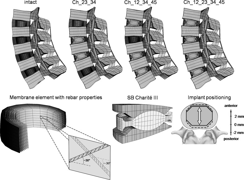
A three-dimensional osseoligamentous non-linear FE model of the intact L1–L5 human lumbar spine was created (Fig. 1). The FE mesh and the material properties are based on a previously developed functional spinal unit L4–L5 [27, 28]. The dimensions and orientations of the other vertebrae (L1–L3) with their articulating facet joints, as well as the intervertebral discs, were modified to fulfil reported observations [2, 16, 20]. The anteroposterior depth and width slightly increase from L1 (34 mm) to L5 (35 mm) and L1 (41 mm) to L5 (45 mm), respectively. The posterior vertebral body height remains relatively constant with ~24 mm. The interfacet height gradually decreases from 30 to 25 mm and the interfacet width increases from 22 to 42 mm. The longitudinal facet angle is almost constant with 170°. The model consists of seven distinct structural regions, namely cancellous bone, cortical bone, posterior bony elements, annulus fibrosus, nucleus pulposus, cartilaginous endplate and the seven main ligaments.
Fig. 1.
Top finite element models of the lumbar spine (L1–L5) showing the intact state and three different implantation scenarios: Ch_23_34, Ch_12_34_45 and Ch_12_23_34_45 (the abbreviations are explained in Table 1). Bottom left the collagen fibres were represented by membrane elements in conjunction with the rebar option simulating a direction dependent non-linear stress–strain behaviour. Bottom right finite element mesh of the SB Charité III disc and a schematic illustration of the investigated implant positions. The position was varied by 2 mm in both anterior and posterior directions
Eight-node elements were used for all bony structures and for the intervertebral discs. The material properties of the different structures were extracted from the literature [27, 28]. The nucleus was assumed to be an incompressible fluid-filled cavity. The annulus was assumed to be a composite of solid matrix modelled as isotropic, incompressible, hyper-elastic Mooney-Rivlin material [12] with embedded fibres, which are organised in nine concentric rings around the nucleus. The annulus collagen fibres and the seven spinal ligaments were represented by membrane elements with rebar properties. This method allows the definition of different disc layers of uniaxial reinforcement as part of the underlying host element. For each layer, the cross-sectional area and the initial angular orientation of each rebar (fibre), as well as the material properties, have to be defined. During the calculation process, the resultant stiffness of the rebar is superimposed on the host element stiffness. The stress–strain behaviour of the annular fibres and the ligaments were described by a non-linear stress–strain curve [27, 28]. The fibre angle varied from ±24° to the mid-plane of the disc ventrally to ±46° at the dorsal side according to a previous study [12]. The articulating facet surfaces were modelled using surface–surface contact elements in combination with the penalty algorithm with a normal contact stiffness of 200 N/mm and a friction coefficient of zero. The facet cartilage layer was assumed to yield a thickness of 0.2 mm. The initial gap between the cartilage layers was assumed to be 0.4 mm. The cartilage was assumed to be isotropic, linear elastic with a Young’s modulus of 35 MPa and a Poisson’s ratio of 0.4.
Implants
In the current study, the SB Charité III disc—a three piece construct comprised of a biconvex core sandwiched between two concave endplates—was used with an approximate height of 13 mm and a lordotic angle of 5° (Fig. 1). The implant was meshed using eight-node isoparametric solid elements. The spiked endplate surfaces were simplified to a flat surface.
A standard unilateral contact was assumed at the articular surface between the core and the concave metallic endplates. A friction coefficient of 0.02 was chosen for both contact pairs [9]. For the metallic endplates, a chrome–cobalt alloy was assumed with a Young’s modulus of 300 GPa and a Poisson’s ratio of 0.27 [9]. For the inner core, UHMWPE (ultra high molecular weight polyethylene) with a Young’s modulus of 2 GPa and a Poisson’s ratio of 0.3 was used [9].
Implantation
The disc placement procedure for the Charité disc requires an anterior surgical approach. The protocol involves the stepwise removal of the anterior longitudinal ligament, the anterior portion of the annulus and the entire nucleus. To mimic this surgical procedure, the elements representing these structures were removed in the FE model. Only the posterior and lateral portion of the annulus remains in place.
For the contact condition between the metallic endplates and the adjacent bony structures a perfect bond was assumed. The bonded contact should represent a perfect osteo-integration between the metallic endplates and the adjacent vertebrae.
Investigation of a multilevel disc arthroplasty
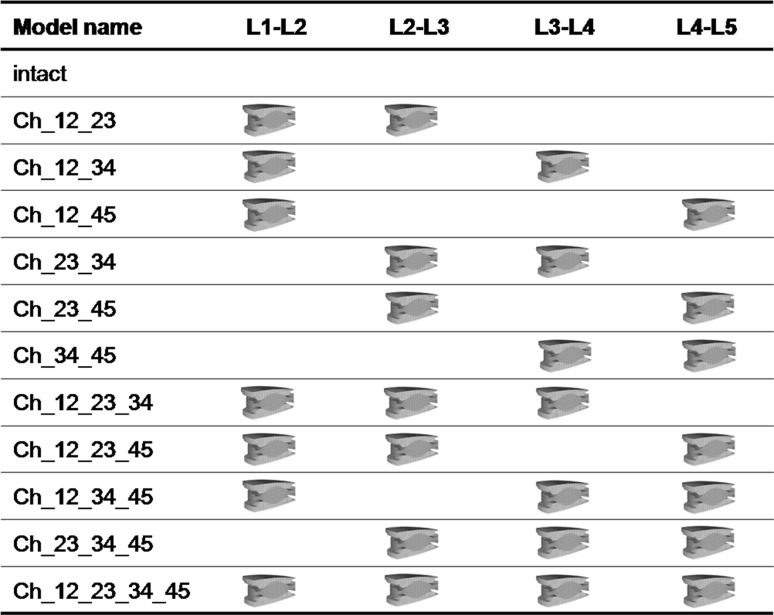
The investigations were started with a two-level implantation. In order to consider all possible combinations of two implant insertions in the lumbar spine, the instrumented levels were subsequently varied and analysed in different FE simulations (Table 1). Subsequently, the number of implants was increased up to four implants to simulate all possible combinations in the lumbar spine. All implants were first integrated in the geometrically central position of the intervertebral space. Subsequently, the position of all implants was equally displaced by 2 mm in both the anterior and the posterior directions (Fig. 1). For one particular model (Ch_12_23_45, Ch denotes the Charité disc, and the numbers following Ch represent the lumbar disc levels in which they were placed), we also investigated a specific placement of the implants to simulate possible instabilities caused by a misplacing of the implants. Thereby, the Charité disc was placed centrally in the L1–L2 level, 2 mm anteriorly in the L2–L3 level and 2 mm posteriorly in the L4–L5 level.
Table 1.
List of the investigated implant configurations
The calculations consider 2–4 Charité discs implanted in different intervertebral disc levels. The results of all instrumented lumbar spine models were compared with the intact one. Ch denotes the Charité disc, and the numbers following Ch represent the lumbar disc levels in which they were placed
Loading and boundary conditions
The inferior endplate of the lower vertebral body was rigidly fixed. In the first load step, an axial compression preload of 500 N was applied simulating the upper body weight and the local muscles. This load was applied using the follower load technique, as suggested by Patwardhan et al. [21] and Shirazi-Adl and Parnianpour [31], which allows for the application of physiological compression loads. The load follows the curvature of the spine through the proximities of the centres of rotation, and therefore, avoids the generation of additional “larger” moments. This was realised by using connector elements which were spanned between the adjacent vertebral bodies in agreement with previous numerical studies [10, 22]. We adjusted the fixation points of the connector elements in order to obtain a resulting rotation of less than 0.5°, which was considered to be a negligible value. Furthermore, the rotation after the follower load application should be in flexion or in extension for all segments to have a comparable initial situation for each spinal segment. In the second load step, the spinal segment was loaded with unconstrained moments of 7.5 Nm in the sagittal direction simulating flexion and extension.
This study was performed using the commercial FE software ANSYS 11.0 (ANSYS Inc., Canonsburg, PA, USA) for pre-processing and ABAQUS/Standard (ABAQUS 6.7-3, SIMULIA, Providence, RI, USA) for solving and post-processing.
Data analysis
The RoM and the resulting facet joint forces of the instrumented level and the adjacent segments were calculated. Both result parameters were analysed at the end of the second load step. Thereby, the resulting RoM or facet force resulted from the applied follower load and of the applied bending moment.
Model verification
Before undertaking the present study, we performed a mesh convergency test with the single spinal segment (L4–L5). As critical result parameters we used the RoM, the facet joint forces as well as some strain and stress components within the intervertebral disc and the adjacent bony structures. The element edge length was reduced until the percentage difference of the critical results between two consecutive mesh densities was less than 2%. We additionally conducted a mesh convergency test with the L4–L5 spinal segment together with the Charité artificial disc. For this test we used the RoM, the instantaneous centre of rotation, the facet joint forces as well as the peak penetration and the maximum contact pressure between the core and the metallic endplates as critical result parameters. For the sake of brevity, only the RoM and the maximum contact pressure are presented. Furthermore, we performed a parameter study to identify the influence of the maximum contact stiffness on the peak penetration and contact pressure for all articulating surfaces within the implant. All these models were loaded using the same load protocol employed for the whole lumbar spine model defined above.
Model validation
The intervertebral disc, which contains the composite structure of the annulus fibrosus and the nucleus pulposus, was extensively validated in previous studies [27, 28]. For the current study, we additionally compared our calculated RoM results for the intact whole lumbar spine and the intra-segmental RoM for the L4–L5 spinal segment with published in vitro data [24]. For this, the model was loaded with unconstrained moments of 7.5 Nm in flexion and extension.
Results
Model verification
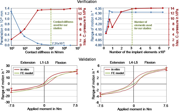
With increasing contact stiffness, the peak penetration and the maximum contact pressure asymptotically led to values which can be considered as converged (Fig. 2). The authors established that a stiffness value of 100,000 N/mm produced consistently good results (maximum differences less than 2% between the chosen and the next higher stiffness value). We therefore used this stiffness in further analyses. The mesh convergency test showed that an element number of approximately 3080 caused satisfying results for the implant (maximum differences of the RoM and of the maximum contact pressure of 0.02 and 1.2%, respectively, were determined between the current and the next refinement step) (Fig. 2).
Fig. 2.
Verification and validation of the intact finite element model. Top left peak penetration and contact pressure in relation to the contact stiffness for the contact between inlay and upper metallic endplate. Top right range of motion and contact pressure in relation to the mesh density of the Charité disc. Bottom left calculated total range of motion for L1–L5 under 7.5 Nm in extension and flexion in comparison with in vitro data [24]. The in vitro curve represents the mean value, and the error bars represent the ranges of the in vitro study. Bottom right calculated range of motion for segment L4–L5 under 7.5 Nm in extension and flexion in comparison with in vitro data [24]
Model validation
The intact model showed a good qualitative and quantitative agreement with in vitro results for the total RoM of the lumbar spine and for the intra-segmental RoM of the L4–L5 segment in flexion and extension (Fig. 2). Only at the end of the moment application in extension the total RoM of the lumbar spine is slightly high and just inside the range measured for seven lumbar specimens.
All implants in the central position
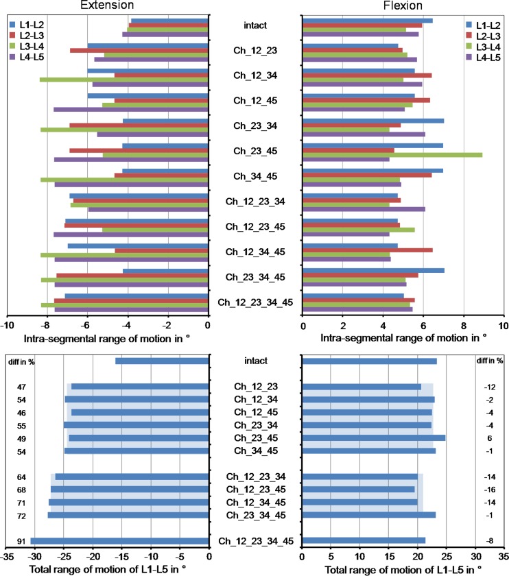
Intrasegmental rotation is increased at all levels for extension with respect to the intact situation (Fig. 3). This increase was mainly caused by the instrumented segments. The ratio between the RoM increase of the instrumented and non-instrumented segments was 2.4. In comparison to the intact model, the total RoM in extension increased by an average value of 51% for two implants, 69% for three implants and 91% for four implants. On the average, each implant increased the RoM by 3.7° for the chosen loading case simulating extension. In flexion, the models predicted an average motion decrease of 18% for the instrumented segments compared to the intact spinal segments, while the non-instrumented segments led to an average motion increase of 9%. In comparison to the intact model, the total RoM in flexion decrease by an average value of 5% for two implants, 11% for three implants and 8% for four implants. On the average, each implant decreases the RoM by 0.8° for the chosen loading case simulating flexion.
Fig. 3.
Intrasegmental and total range of motion for different implant scenarios after the application of a follower load and a flexion or extension moment. The model names are explained in Table 1. The broad light blue bars represent the mean values of the ranges of motion calculated with the models including two or three artificial discs. The percentage differences were determined between the corresponding instrumented models and the intact model (minus denotes a decrease and plus an increase relative to intact)
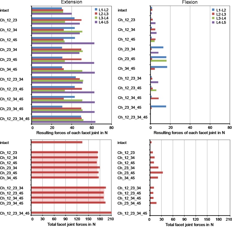
For extension, the different implanted models predicted strongly increased facet joint forces compared to the intact lumbar spine (Fig. 4). An average increase of 24% was calculated for two implants, 30% for three implants and 38% for four implants. Similar to the RoM, this increase was mainly caused by the instrumented segments. The facet joints of the non-instrumented segments were similarly loaded compared to the intact lumbar spine with maximum differences of 8%. In flexion, the facet joints remained almost unloaded for the intact model. In some of the investigated implant models, the Charité disc led to small facet joint forces with a maximum value of 17 N. The peaks were always calculated in the non-instrumented segments probably caused by the local motion increase.
Fig. 4.
Resulting forces for each facet joint (top) and the total facet joint force acting in the whole model (bottom) for different implant scenarios after the application of a follower load and a flexion or extension moment. The broad light red bars represent the mean values of the total facet joint forces for the models including two or three artificial discs
All implants in 2 mm anterior or posterior position
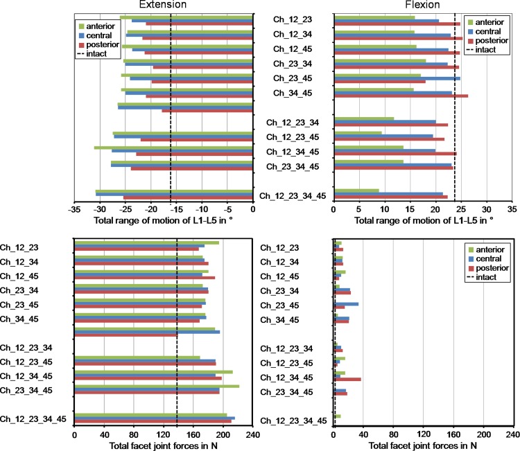
In extension, a posteriorly placed implant led to a decreased RoM compared to the central position (average decrease of 17%), and therefore, also resulted in a better representation of the total RoM calculated for the intact lumbar spine (Fig. 5). An anterior position caused a slight increase of the RoM (average increase of 4%) compared to the central position. In flexion, placing the implants posteriorly led to an average increase of 8% of the total RoM compared to the centrally placed implant and a better representation of the intact situation, while an anterior position strongly limited the RoM by 35%.
Fig. 5.
Total range of motion (top) and facet joint force (bottom) for different implant scenarios and implant positions (2 mm anterior, central, 2 mm posterior)
Changing the position of the artificial discs affected the facet joint forces for all implant configurations investigated but in a different manner. In extension, a maximum increase of the facet joint forces of 14% compared to the central position were predicted (Fig. 5). In flexion, changing the implant position did not substantially alter the facet joint forces.
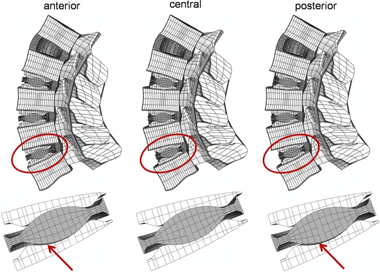
In extension, for three two-level implant models, for all three-level implant models and for the full instrumented lumbar spine model, a lift-off was calculated when the implants were not centrally placed (Fig. 6). The lift-off for the two-level implant models were only found when the artificial discs were implanted in two adjacent levels (Ch_12_23, Ch_23_34 and Ch_34_45). In flexion, a lift-off was not seen in any model.
Fig. 6.
Deformed plot of the Ch_23_34_45 model in extension (top). A lift-off was observed when the implants were anteriorly or posteriorly placed (shown by the red arrows)
Model considering one specific implant misplacement
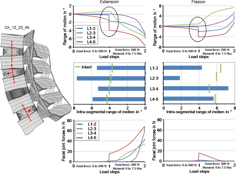
In comparison to the prior investigations, where the implants were equally positioned all centrally, anteriorly or posteriorly, the model with different implant positions did not lead to substantially different RoMs and facet forces at the end of the moment application (Fig. 7). However, the intra-segmental RoM of the single spinal segments showed a different motion characteristic during the follower load application. While the L3–L4 spinal segment (non-instrumented segment) showed a small flexion motion, the L1–L2 and L2–L3 spinal segment exhibited a small extension motion. The RoM of the L4–L5 spinal segment was almost zero. For the sake of comparison, all spinal segments of the intact lumbar spine led to a small flexion motion of maximum 0.5° after the follower load was applied. Additionally, at the end of the first load application, an unstable motion was estimated with a maximal amplitude of 2.1° for L2–L3. An unstable motion at the end of the second step was also observed with a maximal amplitude of 1.7° for L1–L2. Due to these effects additional analyses were performed with a follower load of 400 and 600 N. For 400 N, both instabilities were not seen anymore. For 600 N, the instability in the first load step was again observed in correspondence to the 500 N load application, but became stable again with increasing load. The instability at the end of the second load step was not calculated. In parallel, the facet joint forces strongly increased during the unstable motion in the first load step for L2–L3 up to 18 N. At the end of the second load step the facet forces rapidly increased by an offset value of 11 N for L4–L5 in extension. The other facet joints were nearly unaffected. In flexion, this increase was not calculated.
Fig. 7.
The progression of the intra-segmental range of motion during load application and the corresponding final values as well as the facet joint forces in relation to the load application in extension and flexion when using the Ch_12_23_45 model. The Charité disc was placed centrally in the L1–L2, 2 mm anteriorly in the L2–L3 and 2 mm posteriorly in the L4–L5. The dashed ellipse illustrates an instability during the follower load application
Discussion
The results of the present FE study partially supported the hypothesis of hypermobility after multilevel TDA. In extension, a strong RoM increase was found in all cases at the implanted segment, as previously reported for multisegmental TDA [11]. A slight RoM decrease in flexion at the implanted levels was calculated in most simulations. However, the increase in extension was always greater than the decrease in flexion, thus leading to a global hypermobility of the lumbar spine. The strong motion increase in extension might be due to the removal of the anterior longitudinal ligament and the anterior portion of the annulus fibrosus. This hypermobility may also induce an increase of the segmental lordosis in the neutral position [3], with possible clinical consequences in the long term.
The calculated differences in RoM between all models, including two implants with respect to the non-treated lumbar spine, were within the standard deviation of the in vitro measurements. Their clinical relevance is therefore questionable. Small changes in material and geometrical properties would have possibly higher effects on the RoM and facet contact forces. For the flexion motion, a change of tendency from three to four implants was calculated. It is very difficult to interpret these effects because of the high number of parameters which may have an influence on the results. However, the RoM of one of the three implant conditions is higher than that predicted for the four implant simulation, which is inside the standard deviation of the results of the three implant scenarios. Therefore, the change of tendency has not really a clinical impact.
Changes in the position of the artificial discs led to significantly different results in terms of RoM, while the facet joint forces were only marginally altered. The posterior position suggested by the manufacturer led to the most physiological RoMs, when compared to the central and the anterior position, both in flexion and extension. However, lift-off phenomena were observed in some extension simulations in which the artificial discs were anteriorly or posteriorly implanted. Lift-off may induce early wear of the core, due to the high contact pressures and the strong reduction of the contact area. Anterior dislocations of the core, which are presumably related with lift-off phenomena, were also reported in clinical studies [15]. Navigation systems have proven themselves to allow for a more correct positioning of the artificial discs [14], and may be employed in a larger scale in the future. Interestingly, lift-offs were only observed when the artificial discs were positioned at adjacent levels as are those mostly implanted in clinical practice [5], while they were absent when an intact disc was present between two artificial discs. This might suggest that in cases where disc degeneration disease does not occur in adjacent segments, better clinical results may be obtained with multilevel TDA.
No in vivo and only limited in vitro data concerning the forces transmitted through the facet joints appear to be currently available. This is mostly due to technical difficulties and limited repeatability of the measurements. Data obtained with extra-articular strain gauges are highly sensitive to the number and the positioning of the strain gauges [35]. The use of intra-articular sensors or pressure-sensitive films is inherently limited by the need of disrupting the facet capsule and the presence of a foreign body inside the articulation that alters the actual pressure distribution [35]. Our calculations yielded facet forces between 30 and 40 N in extension, which are consistent with in vitro data of Wilson et al. [35] who found a range of 10–50 N for the same moment.
The calculated values of the facet joint forces support our hypothesis that an increase of the number of artificial discs leads to a marginal increase of the facet forces. This increase might explain why Siepe et al. [32] identified the facet joints as one of the most common reasons for the patient dissatisfaction. The facet force increase may be mainly caused by the motion increase of the instrumented segments. The increase is coherent with previous published results [9, 11, 18, 36]. In flexion, low force values in most treated segments were recorded, in agreement with Grauer et al. [11] and Rohlmann et al. [25]. In contrast, Zander et al. [36] found zero forces. The small discrepancies may be due to the different loads simulating flexion and the use of FE models based on different geometries; small changes in the gap distance, the facet curvature and orientation may lead to significantly different results.
The instability phenomenon observed in the simulation, where the implants were not uniformly positioned in the antero-posterior direction, is not easy to interpret. The authors conceive that there is more than only one physical reason which led to that behaviour. During the follower load application, the spinal structures were compressed. The annular fibres and the ligaments, however, are not resistant in compression. Therefore, the loads must be transferred through the annulus ground substance and the implants themselves. However, the anterior portion of the annulus was removed. During the load application, the instrumented spinal segments, in particular L2–L3, where the implant was anteriorly placed, moved slightly towards extension. In this direction, the stiffness is given almost only by the implants due to the friction between the different implant components; however, the friction coefficient is 0.02, and therefore the stiffness is very low. Furthermore, the resulting centres of rotation were not aligned following the physiological curvature of the lumbar spine, which is almost given when the implants are all positioned centrally, anteriorly or posteriorly. The follower load, however, should be defined through the proximities of the centres of rotation, which is not the case when the implants are misplaced. Further calculations showed that higher friction values (above 0.14) and pure moment applications without a follower load definition led to a stable motion behaviour. The instabilities predicted by the FE models may also occur in reality, and may not have any influence on the physiology of patients. On the other hand, they may be compensated by the action of local muscles which makes the occurrence of the instability not very likely. Both, however, are speculations which cannot be proven at the moment by the authors. To investigate if the calculated instabilities are not a numerical artefact, we performed some additional simulations. For the specific implant situation, the authors performed a mesh convergency test in which the element edge length was reduced by half. Furthermore, we reduced the tolerance value of the non-linear solution algorithm and increased the number of substeps. All these simulations showed the same unstable motion behaviour.
The simulations in the current study were performed under load control. Results showed that the stiffness of an instrumented segment increased in flexion and decreased in extension. Therefore, the motion of an intact adjacent spinal segment would increase in flexion and decrease in extension in displacement control which resembles more the spinal activity during daily life. A decreased RoM would probably result in smaller facet joint forces. An increased RoM may lead to high facet joint forces when the articulating facet surfaces go into contact but to higher stresses within the disc, and there may be a higher risk of initiation of disc degeneration. That means that an adjacent non-instrumented segment is probably higher affected in flexion than in extension when applying constant displacements.
Some limitations of the present study can be identified. Disc degeneration may be present in discs that were not surgically replaced. Multilevel disc disease can involve as much as the whole lumbar spine; in these highly compromised clinical scenarios, the surgeon may choose not to replace all the degenerated discs in order to limit the extent and the invasivity of the surgery. In the present models, all the discs not replaced with the artificial disc were considered to be healthy. This choice has been determined by the highly patient-specific nature of disc degeneration [30], which makes the creation of a standard degenerated disc to be used in FE models impossible. For example, a slight degeneration can be explained by only a disc height reduction but also with a dehydration of the nucleus and an osteophyte formation without a disc height loss [34].
The TDA surgery usually requires distraction of the endplates since the height of the artificial disc may be higher than that of the degenerated disc to be replaced. This distraction induces pretension of the ligaments and of the remaining part of the annulus fibrosus, which may be desirable in order to have a higher stability of the implanted spine. Distraction was not taken into account because the authors believe that this effect is only temporary, due to viscoelastic relaxation of the spinal structures.
In the current study, a follower load with a magnitude of 500 N was employed both in flexion and in extension. Rohlmann et al. [26] suggested that a load of 500 N was not sufficient for simulating flexion since it did not fully take into account the global muscle forces, while with a 1175-N load the results, especially the intradiscal pressure, were comparable with those of in vivo data. The magnitude of the follower load has only a slight effect on the motion behaviour of the spine. For extension, the authors indicated a follower load magnitude of 500 N as a physiological value. In the present paper, the authors chose to employ a common value for the follower load in flexion and extension, in order to ensure comparability of the results obtained for the two loading cases. The load magnitude which better fits extension (500 N) was chosen since this loading case is believed to be one of the most critical after TDA due to the increase of the RoM and the facet forces.
For the contact description, we used optimised values for the contact stiffness to minimise the penetration reaching an asymptotical behaviour of the results and avoid convergency problems for the solution process. However, this very high stiffness in particular between the implant core and surrounding metallic endplates may neglect micro-scale phenomena, which could be better represented by a lower contact stiffness. A detailed modelling of these phenomena requires more insight about the surface properties of the contact interfaces.
Lateral bending and axial rotation—which were not considered in the present work—may be of interest for the biomechanical evaluation of TDA. In particular, axial rotation induces high forces in the facet joints [29], which can even be amplified due to the inherent low shear and rotational stiffness on the Charité disc. Due to their relevance, these loading cases will be the subject of future studies. The authors decided to investigate flexion and extension because these motions are often performed during daily activities and lead to the highest RoM in the lumbar spine.
In the current study, we only considered the Charité disc. Different models of artificial discs are expected to provide different results, in terms of RoM, facet forces and instantaneous centres of rotation. Semi-constrained devices as the ProDisc and the Maverick are designed to fix the instantaneous centres of rotation in a specific position, and do not allow for pure translations like unconstrained artificial discs [8, 13]. A more constrained design should be able to share a greater part of the load, thus decreasing the load through the facet joints and in the ligaments [17]. Zander et al. [36] could show that for lateral bending and axial rotation the resulting facet forces are substantially higher for the ProDisc than for the Charité disc; however, for extension the facet forces were higher when a Charité disc was simulated.
We used a fixed combination of material properties for the different artificial disc implants as used in a prior FE study of Goel et al. [9]. The exact values of the Young’s modulus and of the Poisson’s ratio of the chrome-cobalt alloy and the UHMWPE were not published by the company Depuy Spine, and therefore, may slightly differ from the values used in the current study. Different values might have a small influence on our findings.
A significant improvement of the present models would entail the inclusion of changes in the lateral positioning of the artificial disc. It has been hypothesised that such changes, which are due to an incorrect identification of the vertebral midline, may lead to iatrogenic scoliosis [17]. The effects of positioning errors may be more effectively described by using a probabilistic approach [23], which may also include changes of the material properties of the friction coefficient between the different implant components and of the spine anatomy to incorporate patient–patient variability.
Conclusion
These FE calculations supported our hypotheses that multilevel TDA leads to significant increase of both spinal mobility and facet joint forces in flexion and extension. The more artificial discs are implanted, the stronger these increases can be expected. Imprecise positioning of the artificial discs may alter these results, which can even lead to significant implant-related problems such as lift-off phenomena between the core and the implant endplates. This can in consequence lead to more wear and mechanical failure of the inner core. When patients with multilevel TDA become old and their muscles weaker, additional instabilities can be expected. Therefore, from the mechanical point of view, multilevel TDA should, if at all, only be performed in appropriate patients with good muscular conditions and by surgeons who can ensure optimal implant positions.
Acknowledgments
This study was financially supported by the German Research Foundation (Wi 1352/14-1). The authors would like to thank the company Depuy Spine (Raynham, MA, USA) for the supply of their implants.
Conflict of interest statement
None.
References
- 1.Bertagnoli R, Yue JJ, Shah RV, Nanieva R, Pfeiffer F, Fenk-Mayer A, Kershaw T, Husted DS. The treatment of disabling multilevel lumbar discogenic low back pain with total disc arthroplasty utilizing the ProDisc prosthesis: a prospective study with 2-year minimum follow-up. Spine. 2005;30(19):2192–2199. doi: 10.1097/01.brs.0000181061.43194.18. [DOI] [PubMed] [Google Scholar]
- 2.Boulay C, Tardieu C, Hecquet J, Benaim C, Mouilleseaux B, Marty C, Prat-Pradal D, Legaye J, Duval-Beaupere G, Pelissier J. Sagittal alignment of spine and pelvis regulated by pelvic incidence: standard values and prediction of lordosis. Eur Spine J. 2006;15(4):415–422. doi: 10.1007/s00586-005-0984-5. [DOI] [PMC free article] [PubMed] [Google Scholar]
- 3.Cakir B, Richter M, Kafer W, Puhl W, Schmidt R. The impact of total lumbar disc replacement on segmental and total lumbar lordosis. Clin Biomech. 2005;20(4):357–364. doi: 10.1016/j.clinbiomech.2004.11.019. [DOI] [PubMed] [Google Scholar]
- 4.Denoziere G, Ku DN. Biomechanical comparison between fusion of two vertebrae and implantation of an artificial intervertebral disc. J Biomech. 2006;39(4):766–775. doi: 10.1016/j.jbiomech.2004.07.039. [DOI] [PubMed] [Google Scholar]
- 5.Di Silvestre M, Bakaloudis G, Lolli F, Vommaro F, Parisini P. Two-level total lumbar disc replacement. Eur Spine J. 2009;18(Suppl 1):64–70. doi: 10.1007/s00586-009-0982-0. [DOI] [PMC free article] [PubMed] [Google Scholar]
- 6.Dmitriev AE, Gill NW, Kuklo TR, Rosner MK. Effect of multilevel lumbar disc arthroplasty on the operative- and adjacent-level kinematics and intradiscal pressures: an in vitro human cadaveric assessment. Spine J. 2008;8(6):918–925. doi: 10.1016/j.spinee.2007.10.034. [DOI] [PubMed] [Google Scholar]
- 7.Freeman BJ, Davenport J. Total disc replacement in the lumbar spine: a systematic review of the literature. Eur Spine J. 2006;15(Suppl 3):S439–S447. doi: 10.1007/s00586-006-0186-9. [DOI] [PMC free article] [PubMed] [Google Scholar]
- 8.Galbusera F, Bellini CM, Zweig T, Ferguson S, Raimondi MT, Lamartina C, Brayda-Bruno M, Fornari M. Design concepts in lumbar total disc arthroplasty. Eur Spine J. 2008;17(12):1635–1650. doi: 10.1007/s00586-008-0811-x. [DOI] [PMC free article] [PubMed] [Google Scholar]
- 9.Goel VK, Grauer JN, Patel T, Biyani A, Sairyo K, Vishnubhotla S, Matyas A, Cowgill I, Shaw M, Long R, Dick D, Panjabi MM, Serhan H. Effects of charite artificial disc on the implanted and adjacent spinal segments mechanics using a hybrid testing protocol. Spine. 2005;30(24):2755–2764. doi: 10.1097/01.brs.0000195897.17277.67. [DOI] [PubMed] [Google Scholar]
- 10.Goel VK, Mehta A, Jangra J, Faizan A, Kiapour A, Hoy RW, Fauth AR. Anatomic facet replacement system (AFRS) restoration of lumbar segment mechanics to intact: a finite element study and in vitro cadaver investigation. SAS J. 2007;1(1):46–54. doi: 10.1016/S1935-9810(07)70046-4. [DOI] [PMC free article] [PubMed] [Google Scholar]
- 11.Grauer JN, Biyani A, Faizan A, Kiapour A, Sairyo K, Ivanov A, Ebraheim NA, Patel T, Goel VK. Biomechanics of two-level Charite artificial disc placement in comparison to fusion plus single-level disc placement combination. Spine J. 2006;6(6):659–666. doi: 10.1016/j.spinee.2006.03.011. [DOI] [PubMed] [Google Scholar]
- 12.Holzapfel GA, Schulze-Bauer CA, Feigl G, Regitnig P. Single lamellar mechanics of the human lumbar anulus fibrosus. Biomech Model Mechanobiol. 2005;3(3):125–140. doi: 10.1007/s10237-004-0053-8. [DOI] [PubMed] [Google Scholar]
- 13.Huang RC, Girardi FP, Cammisa FP, Jr, Wright TM. The implications of constraint in lumbar total disc replacement. J Spinal Disord Tech. 2003;16(4):412–417. doi: 10.1097/00024720-200308000-00014. [DOI] [PubMed] [Google Scholar]
- 14.Kafchitsas KM, Rauschmann M (2009) Navigation of artificial disc replacement: evaluation in a cadaver study. Comput Aided Surg 14(1–3):28–36 [DOI] [PubMed]
- 15.Kurtz SM, Ooij A, Ross R, Waal Malefijt J, Peloza J, Ciccarelli L, Villarraga ML. Polyethylene wear and rim fracture in total disc arthroplasty. Spine J. 2007;7(1):12–21. doi: 10.1016/j.spinee.2006.05.012. [DOI] [PubMed] [Google Scholar]
- 16.Masharawi Y, Rothschild B, Dar G, Peleg S, Robinson D, Been E, Hershkovitz I. Facet orientation in the thoracolumbar spine: three-dimensional anatomic and biomechanical analysis. Spine. 2004;29(16):1755–1763. doi: 10.1097/01.BRS.0000134575.04084.EF. [DOI] [PubMed] [Google Scholar]
- 17.McAfee PC, Cunningham BW, Hayes V, Sidiqi F, Dabbah M, Sefter JC, Hu N, Beatson H. Biomechanical analysis of rotational motions after disc arthroplasty: implications for patients with adult deformities. Spine. 2006;31(19 Suppl):S152–S160. doi: 10.1097/01.brs.0000234782.89031.03. [DOI] [PubMed] [Google Scholar]
- 18.Moumene M, Geisler FH. Comparison of biomechanical function at ideal and varied surgical placement for two lumbar artificial disc implant designs: mobile-core versus fixed-core. Spine. 2007;32(17):1840–1851. doi: 10.1097/BRS.0b013e31811ec29c. [DOI] [PubMed] [Google Scholar]
- 19.O’Leary P, Nicolakis M, Lorenz MA, Voronov LI, Zindrick MR, Ghanayem A, Havey RM, Carandang G, Sartori M, Gaitanis IN, Fronczak S, Patwardhan AG. Response of Charite total disc replacement under physiologic loads: prosthesis component motion patterns. Spine J. 2005;5(6):590–599. doi: 10.1016/j.spinee.2005.06.015. [DOI] [PubMed] [Google Scholar]
- 20.Panjabi MM, Goel V, Oxland T, Takata K, Duranceau J, Krag M, Price M. Human lumbar vertebrae. Quantitative three-dimensional anatomy. Spine. 1992;17(3):299–306. doi: 10.1097/00007632-199203000-00010. [DOI] [PubMed] [Google Scholar]
- 21.Patwardhan AG, Havey RM, Meade KP, Lee B, Dunlap B. A follower load increases the load-carrying capacity of the lumbar spine in compression. Spine. 1999;24(10):1003–1009. doi: 10.1097/00007632-199905150-00014. [DOI] [PubMed] [Google Scholar]
- 22.Rohlmann A, Bauer L, Zander T, Bergmann G, Wilke HJ. Determination of trunk muscle forces for flexion and extension by using a validated finite element model of the lumbar spine and measured in vivo data. J Biomech. 2006;39(6):981–989. doi: 10.1016/j.jbiomech.2005.02.019. [DOI] [PubMed] [Google Scholar]
- 23.Rohlmann A, Mann A, Zander T, Bergmann G. Effect of an artificial disc on lumbar spine biomechanics: a probabilistic finite element study. Eur Spine J. 2009;18(1):89–97. doi: 10.1007/s00586-008-0836-1. [DOI] [PMC free article] [PubMed] [Google Scholar]
- 24.Rohlmann A, Neller S, Claes L, Bergmann G, Wilke HJ. Influence of a follower load on intradiscal pressure and intersegmental rotation of the lumbar spine. Spine. 2001;26(24):E557–E561. doi: 10.1097/00007632-200112150-00014. [DOI] [PubMed] [Google Scholar]
- 25.Rohlmann A, Zander T, Bock B, Bergmann G. Effect of position and height of a mobile core type artificial disc on the biomechanical behaviour of the lumbar spine. Proc Inst Mech Eng. 2008;222(2):229–239. doi: 10.1243/09544119JEIM241. [DOI] [PubMed] [Google Scholar]
- 26.Rohlmann A, Zander T, Rao M, Bergmann G. Realistic loading conditions for upper body bending. J Biomech. 2009;42(7):884–890. doi: 10.1016/j.jbiomech.2009.01.017. [DOI] [PubMed] [Google Scholar]
- 27.Schmidt H, Heuer F, Drumm J, Klezl Z, Claes L, Wilke HJ. Application of a calibration method provides more realistic results for a finite element model of a lumbar spinal segment. Clin Biomech. 2007;22(4):377–384. doi: 10.1016/j.clinbiomech.2006.11.008. [DOI] [PubMed] [Google Scholar]
- 28.Schmidt H, Heuer F, Simon U, Kettler A, Rohlmann A, Claes L, Wilke HJ. Application of a new calibration method for a three-dimensional finite element model of a human lumbar annulus fibrosus. Clin Biomech. 2006;21(4):337–344. doi: 10.1016/j.clinbiomech.2005.12.001. [DOI] [PubMed] [Google Scholar]
- 29.Schmidt H, Heuer F, Wilke HJ. Interaction between finite helical axes and facet joint forces under combined loading. Spine. 2008;33(25):2741–2748. doi: 10.1097/BRS.0b013e31817c4319. [DOI] [PubMed] [Google Scholar]
- 30.Shao Z, Rompe G, Schiltenwolf M. Radiographic changes in the lumbar intervertebral discs and lumbar vertebrae with age. Spine. 2002;27(3):263–268. doi: 10.1097/00007632-200202010-00013. [DOI] [PubMed] [Google Scholar]
- 31.Shirazi-Adl A, Parnianpour M. Load-bearing and stress analysis of the human spine under a novel wrapping compression loading. Clin Biomech. 2000;15(10):718–725. doi: 10.1016/S0268-0033(00)00045-0. [DOI] [PubMed] [Google Scholar]
- 32.Siepe CJ, Mayer HM, Heinz-Leisenheimer M, Korge A. Total lumbar disc replacement: different results for different levels. Spine. 2007;32(7):782–790. doi: 10.1097/01.brs.0000259071.64027.04. [DOI] [PubMed] [Google Scholar]
- 33.Tropiano P, Huang RC, Girardi FP, Cammisa FP, Jr, Marnay T. Lumbar total disc replacement. Seven to eleven-year follow-up. J Bone Joint Surg Am. 2005;87(3):490–496. doi: 10.2106/JBJS.C.01345. [DOI] [PubMed] [Google Scholar]
- 34.Wilke HJ, Rohlmann F, Neidlinger-Wilke C, Werner K, Claes L, Kettler A. Validity and interobserver agreement of a new radiographic grading system for intervertebral disc degeneration: Part I. Lumbar spine. Eur Spine J. 2006;15(6):720–730. doi: 10.1007/s00586-005-1029-9. [DOI] [PMC free article] [PubMed] [Google Scholar]
- 35.Wilson DC, Niosi CA, Zhu QA, Oxland TR, Wilson DR. Accuracy and repeatability of a new method for measuring facet loads in the lumbar spine. J Biomech. 2006;39(2):348–353. doi: 10.1016/j.jbiomech.2004.12.011. [DOI] [PubMed] [Google Scholar]
- 36.Zander T, Rohlmann A, Bergmann G. Influence of different artificial disc kinematics on spine biomechanics. Clin Biomech. 2009;24(2):135–142. doi: 10.1016/j.clinbiomech.2008.11.008. [DOI] [PubMed] [Google Scholar]


