Abstract.
We used a 3-D optoacoustic (OA) tomography system to create maps of optical absorbance of mice tissues contrasted with gold nanorods (GNRs). Nude mice were scanned before and after injection of GNRs at time periods varying from 1 to 192 h. Synthesized GNRs were purified from hexadecyltrimethylammonium bromide and coated with polyethylene glycol (PEG) to obtain GNR-PEG complexes suitable for in vivo applications. Intravenous administration of purified GNR-PEG complexes resulted in enhanced OA contrast of internal organs and blood vessels compared to the same mouse before injection of the contrast agent. Maximum enhancement of the OA images was observed 24 to 48 h postinjection, followed by a slow clearance trend for the remaining part of the studied period (eight days). We demonstrate that OA imaging with two laser wavelengths can be used for noninvasive, long-term studies of biological distribution of contrast agents.
Keywords: optoacoustic tomography, functional imaging, PEGylated gold nanorods, three-dimensional imaging, nude mice
1. Introduction
A variety of optical contrast agents were proposed to enhance the quality and specificity of in vivo optical and optoacoustic (OA) imaging.1–4 The reported biological effects observed upon administration of a contrast agent are mostly limited to its accumulation in the region of interest, e.g., a cancer tumor, either via targeted delivery or by passive transport.5–7 Recent trends in development of optical contrast agents are associated with different types of nanoparticles8. Despite large imaging potential, nanoparticles present inherent biological risks and challenges. Although in vitro and in vivo studies have demonstrated the absence of immediate toxicity for different types of nanoparticles, the legitimate concerns related to their potential long-term toxicity and relatively slow clearance rates remain poorly addressed.9 As the technologies that employ nanoparticle contrast agents approach commercial applications, there is more interest in studying long-term toxicity and biological distribution of nanoparticles.5
OA tomography (OAT) has been applied for in vivo imaging of small animals and humans,10,11 with a particular interest in cancer detection.12–14 OA imaging is a noninvasive technique based on NIR-induced photoacoustic effects.15–17 Three-dimensional OAT was successfully used to visualize blood circulation system and certain blood-rich organs, like the kidneys and spleen, in live mice, with and without nanoparticle contrast agents.18–20
Recently, carbon nanotubes,21 microbubbles,22 and gold nanoparticles23–25 were proposed to enhance the contrast of OA images. Also, gold nanoparticles were proposed as therapeutic agents for cancer treatment,26 opening the way to development of imaging-guided photothermal therapy.11,27 One type of gold nanoparticle with a strong tunable plasmon resonance in the near-infrared spectral range is a gold nanorod (GNR).4,28,29 After administration into the animal, GNRs get distributed inside the body according to their modified affinity, resulting in the enhancement of optical contrast of the targeted tissues.26,30 GNRs were also used as OA contrast agents for quantitative flow analysis in biological tissue31 and to investigate the kinetics of drug delivery compounds.32,33
In these studies, we propose to use 3-D OA imaging as a new noninvasive technique to study long-term biological distribution of optical contrast agents. The potential of a technique is demonstrated by observing long-term biodistribution of nonfunctionalized gold nanorods after their intravenous injection into a mouse. The technique employs two sequential 3-D OA scans. One GNR-sensitive scan is performed using the laser wavelength near the absorption maximum of the injected contrast agent. The other scan (the control) is performed with a laser wavelength away from the absorption spectrum of the contrast agent. The control scan is used to distinguish biodistribution of the contrast agent from that of other endogenous optically absorbing substances like blood. The changes in brightness of the regions segmented within the contrasted OA images were tracked up to several days following the injection of GNRs and compared for the GNR-sensitive and control scans, providing information on biodistribution of the injected contrast agent.
2. Materials and Methods
2.1. OA Imaging System
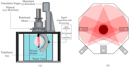
In these studies, we used a commercial prototype of a 3-D OAT system developed for preclinical research at TomoWave Laboratories (Houston, TX), and introduced in our earlier publications.19,34 Figure 1 shows a diagram of the OA mouse imaging system. Ti:Saph (765 nm, ) and Nd:YAG (1064 nm, ) lasers were manufactured as a single unit with the coaxial output beams (Quanta Systems, Solbiate Olona, Italy). The lasers operated at a 10-Hz pulse repetition rate. The output laser energy was for Ti:Saph and for Nd:YAG. The light delivery was established via a custom-made randomized fiber bundle that had four rectangular outputs (). Two of them were arranged outside the hexagonal water tank to operate in the backward OA mode, and two were placed inside the water tank, about 50 mm away from the mouse, to operate in the orthogonal OA mode. Significantly bigger output energy for Nd:YAG laser was used to compensate for the losses caused by the optical absorption of the water layer separating the outputs of the fiber bundle and the mouse. The laser fluence measured at the animal’s skin was for 765 nm and for 1064 nm.
Fig. 1.
Schematic of the OA mouse imaging system: (a) side view and (b) top-down view, where items labeled 2 are the light sources and 1 is the arc probe.
The water temperature was maintained at 36°C by heating elements placed at the bottom of the tank and controlled by the proportional-integral-derivative controller (PID temperature Controller, Watlow Inc., Columbia, Missouri) with a precision of 0.1°C. Spatial gradients of the water temperature and water contamination were minimized by a custom-made water circulation and filtration system based on FilStar XP1 (Rena, Chalfont, PA).
To acquire OA signals, we used a 64-channel arc array of piezocomposite elements (Imasonic SAS, Voray sur-l’Ognon, France), with the 65 mm diameter arc oriented vertically inside the tank. The array consisted of 64 transducers with dimensions of 2 mm by 2 mm and a 3.1 MHz central frequency. The transducers were evenly spaced over a 152 deg aperture. The data acquisition module included analog amplifiers with variable time-gain control that could be set between 0 and 70 dB. Our scans were done with constant amplification of 60 dB. Data digitization was performed with a 25 MHz sampling rate. During the OA scanning, the mouse was rotated about the axis passing through the center of the array parallel to the plane of the arc. Alignment of the axis of rotation was performed as needed using a manual 2-D translation stage (Thor Labs, Newton, NJ) oriented perpendicularly to the arc of the array. The rotation of the mouse was performed by a DC motor with an optical encoder (Faulhaber Gmbh, Schoenaich, Germany) for a total of 360 deg, with 2.4 deg steps. Each scan with 64 averaging would take less than 20 min. The rotational step size was set to match the angular pitch between the elements of the arc array. A single motorized linear stage provided up to 150 mm movement along the axis of rotation and served simply to position a mouse at an appropriate depth inside the tank. The mouse holder with the gas anesthesia delivery module (Summit Anesthesia Solutions, Bend, Oregon) was described in detail in our previous work.19
The OA signals were acquired at each rotational position of the mouse, amplified, digitized, and saved in the computer.19,20 Post-processing of OA signals included: (1) synchronization with the moment of laser emission using laser pulse signals recorded by a photodiode; (2) Wiener deconvolution of the system’s acoustoelectric impulse response with a constant noise-to-signal ratio of 0.1; (3) filtering and integration with the seven scales of the custom-designed wavelet filter;35 (4) removal of the first principal component from each individual channel data. The principal component analysis was done on a signal basis across all acquisitions to remove common features found in each particular channel.36 Three-dimensional OA tomographic reconstruction was performed as described by Brecht et al.19 with 0.1 mm3 voxels. The OAT software was developed to run on Compute Unified Device Architecture (CUDA)-supported graphics processing units (GPUs), resulting in fast reconstruction of 3-D OA images (about 1.5 min for 50 million voxels). Image processing and representation in VolView 2.0 (Kitware, Clifton Park, NY) included: (1) denoising by setting a ramp-like transparency mapping and median filtering with a voxel kernel; (2) applying strong edge detection to emphasize large intensity changes (boundaries); (3) using a linear grayscale palette with saturation at a fixed level within the dynamic range of all the images.
2.2. Fabrication of the OA Contrast Agent
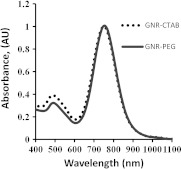
We previously described a strategy to stabilize gold nanorods with a methoxy (polyethylene glycol)-thiol (mPEGSH) which displaces the bilayer of the original surfactant hexadecyltrimethylammonium bromide (CTAB) to provide biocompatibility of the resultant OA contrast agent.20,37 In a typical procedure,38,39 0.250 ml of an aqueous 0.01 M solution of was added to 7.5 ml of a 0.1 M CTAB solution in a test tube. Then, 0.600 ml of an aqueous 0.01 M ice-cold solution was added all at once. Three hours later, 38 µl of this seed solution was added to 10 ml of growth solution containing 9.44 ml of 0.10 M CTAB, 0.40 ml of 0.01 M , 0.06 ml of 0.01 M solution, and 0.032 ml of 0.10 M ascorbic acid. This procedure resulted in synthesis of GNRs with a narrowband optical absorption around 765 nm. After the GNR solution underwent low-speed centrifugation at 1000 g for 10 min, it was centrifuged again at 14,000 g for 10 min. The supernatant was discarded and the pellet resuspended in deionized water for PEGylation as described in previous studies.20,39 Excess mPEG thiol was removed from solution by two rounds of centrifugation at 14,000 g for 10 min, followed by resuspension of the GNR-PEG in phosphate buffer solution (PBS, pH 7.4). The GNR-PEG conjugate was filtered through a 0.22-µm Millipore Express Plus Membrane (EMD Millipore, Billerica, MA). Measurements of optical absorbance proved that the PEGylation and sterilization of PEG-GNR conjugates did not affect plasmonic properties of gold nanorods (Fig. 2). An increase in concentration of PEGylated GNRs was made by centrifugation at 12,000 g for 10 min with the supernatant being removed and the pellet resuspended in sterile PBS up to a concentration of 12.5 nM or , which corresponded to the optical density around 50, as measured with a spectrophotometer (Evolution 201, Thermo Scientific, Waltham, MA). The GNR molar extinction coefficient was calculated around (37), allowing quantitative evaluation of GNR concentrations used for intravenous injections (IV).
Fig. 2.
Absorption spectra of GNR before (GNR-CTAB) and after PEGylation, sedimentation, and filtration (GNR-PEG), with maximum plasmon resonance around 760 nm.
2.3. Incubation of PEGylated GNRs with Whole Blood In Vitro
Whole blood was removed from nude mice (under narcosis) and heparinized to prevent coagulation (10 units of heparin per ml). 100 µl of PEG-GNRs in concentration of 500 pM or was added per milliliter of heparinized blood. After 1 and 24 h of incubation, the samples were centrifuged in 1.5-ml Eppendorf tubes at 600 g for 20 min. Supernatant solution (blood plasma) was collected, and its absorption spectrum was determined using Cary 500 UV-VIS-NIR spectrophotometer (Varian Analytical Instruments, Santa Clara, CA).
2.4. Animal Studies
We used four Athymic Nude-Foxn mice (Harlan, Indianapolis, IN), 7 to 9 weeks old, weighing about 25 g. Animal handling, isoflurane anesthesia, and euthanasia were described in detail in our publications.19,34 Compared to halothane, isoflurane causes less functional complications, such as the depression of cardiopulmonary function.40 Also, isoflurane reduces renal blood flow, glomerular filtration rate, and urinary flow. It is not a significant hepatotoxin. Both induction and recovery from isoflurane are rapid. Isoflurane is the most commonly used inhalational anesthetic for experimental interventions in mice and is preferred for imaging technologies that require the mouse to remain anesthetized for relatively long time periods.41 All the mouse-related procedures were in compliance with our Institutional Animal Care and Use Committee (IACUC) protocol. Each mouse was scanned prior to injection of GNR solution to provide the control OA images. After the initial scan, the mouse was taken out of the water tank and had 400 µl of the GNR solution (19 mg of Au per kg of body mass) injected intravenously through the tail vein. The OA scan was then repeated 1, 24, 48, and 192 h following the GNR injection to investigate long-term changes. Each time a mouse was scanned using 765 nm (GNR-sensitive) and 1064 nm (control) laser wavelengths.
2.5. Segmentation and Analysis of the OA Images
We analyzed organ-specific changes of the OA contrast using two-dimensional grayscale projections of the 3-D reconstructed volumes. A left medio-lateral view of a mouse was used for manual segmentation of the spine, left kidney, spleen, and the whole body, and a right medio-lateral view of a mouse was used for segmentation of the spine, right kidney, and the whole body. The dorsoventral view of a mouse was used for segmentation of kidneys, spleen, spine, and the whole body. The average brightness of the segmented regions was evaluated and the brightness enhancement coefficient (BEC) was calculated as
where is the average brightness in the region of interest (ROI), like a selected organ or the whole body, measured at moment following the injection time .
3. Results
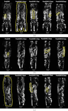
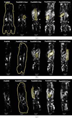
Three orthogonal projections [dorsoventral (a), left medio-lateral (b), and right medio-lateral (c) views] of the OA volumes reconstructed from a mouse prior to GNR injection, as well as 1, 24, 48, and 192 h after the injection of GNRs, are shown on Figs. 3 and 4. Those images were acquired in the orthogonal OA mode using GNR-sensitive (765 nm) and control (1064 nm) laser illumination (Figs. 3 and 4, respectively). The areas of the image that were used for analysis of organ-specific changes in the image brightness are outlined. The corresponding 3-D volumes can be viewed in Videos 1–4. Videos 1 and 2 are OA volumes prior to GNR injection at 765 and 1064 nm, respectively. Videos 3 and 4 are OA volumes showing the largest changes after GNR injection. Video 3 is at 765 nm, 24 h following GNR injection, and Video 4 is at 1064 nm, 48 h following GNR injection.
Fig. 3.
Fig. 4.
Enhancement of the 765-nm image intensity, particularly in the areas of spleen and spine, is clearly seen after the injection of GNRs (Fig. 3). The overall image background is also significantly higher than that of the pre-injection images, reaching the maximum one day after the GNR injection.
Similar to 765 nm, but more dramatic, enhancement of the image brightness is surprisingly observed after the injection of GNRs on the control (1064 nm) OA images (Fig. 4). However, the areas (organs) of interest on the initial image (before injection of the GNRs) at 1064 nm have a much smaller contrast than those at 765 nm. The overall image background also increases in comparison to the initial imaging, reaching the maximum two days after the GNR injection.
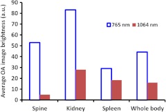
Figure 5 displays average brightness in the regions outlined on the OA images that were reconstructed from the initial scans (prior to the injection of GNRs). Note that only data obtained from the same scan (765 nm or 1064 nm) can be compared, due to different incident fluences and light distributions within the tissue for the two laser wavelengths. The kidneys are visualized as the brightest organs on the OA images due to both high vascularization and water content. The spine is vaguely seen at 1064 nm. However, it is very bright at 765 nm.
Fig. 5.
Average brightness of the segmented parts on the OA images prior to the injection of GNRs.
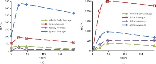
Figure 6 shows the changes of BEC inside the selected regions following the injection of GNRs. Similar trends are observed for all the organs, as well as for the whole body. The maximum brightness was achieved 24 and 48 h after the injection of GNRs on images acquired with 765 and 1064 nm illumination, respectively. A quick increase in the image brightness is followed by a much slower decline, which may indicate slow excretion rates for the GNRs. Also, 1 h after injection of the contrast agent, there are noticeable increases in the brightness on GNR-sensitive (765-nm) images of the spleen, the spine, and the whole body. At the same time, no changes in the brightness are visible in the control (1064-nm) images. The brightness of the control (1064-nm) images increases dramatically 24 h after the injection of GNRs.
Fig. 6.
Change of the average brightness inside the segmented parts on the OA images after the injection of GNRs. Images acquired using (a) 765 nm and (b) 1064 nm laser illumination.
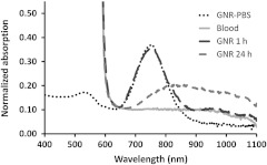
Puzzling behavior of the OA images at the control laser wavelength generated concerns about possible changes of optical properties of GNRs upon their interaction with biological components of blood.42 Therefore, we decided to perform a simple experiment on incubation of PEG-GNR samples with whole blood (as described in Sec. 2.3). Figure 7 shows the light absorption spectra of GNR samples incubated with the whole blood for 1 and 24 h. PEG-GNRs demonstrated stable optical properties while incubated for 1 h with blood. However, after a long period of incubation with blood, a characteristic plasmon resonance peak of PEG-GNRs decreased, broadened, and shifted toward the infrared region. Such effects could not be caused by reshaping or other damage to nanorods due to insufficient laser exposure.43
Fig. 7.
Normalized absorption spectra of GNR-PEG incubated in heparinized blood.
4. Discussion
In these studies, the development of post injection OA contrasting was mapped using time-dependent OA imaging (Figs. 3 and 4). The PEG-GNR solution provided high OA contrast for a prolonged time (eight days), significantly exceeding that currently achieved with standard imaging agents.11,30 The enhancement of brightness on GNR-sensitive, 765-nm OA images was interpreted as local accumulation of GNRs. Maximum levels of brightness were observed 24 h post-injection, followed by a slow clearance trend for the next six to seven days.
GNRs, although proposed as excellent OA contrast agents,4,11 are still not widely used in biological applications since their solutions are usually stabilized by the presence of concentrated CTAB surfactant, with well-documented cytotoxicity.44 The removal of the bulk CTAB will cause aggregation of GNRs3. Recently, it was found that the thiol-terminated methoxypolyethylene glycol (PEG) can be a stabilizer for GNRs.39,45 Several publications, both in vitro and in vivo, indicated that PEGylated gold nanoparticles are nontoxic.5,27,29,46 Our own findings were in agreement with the data showing that 20 mg of GNRs per kg of body mass did not produce any pathological changes in mice.34 In the current studies, of PEG-GNRs was used. Therefore, we exclude the chance that any short-term (i.e. up to 24 h) changes observed on OA images could be caused by toxic effects of GNRs.
The observed enhancement of OA contrast is consistent with previously published biodistribution of GNRs into different tissues, organs, and cells.7,39,47 Previous studies on biodistribution of PEGylated gold nanoparticles showed their significant deposition in internal organs of rodents,29,48–50 which is consistent with our GNR-sensitive OA images showing the increased image contrast in the spleen and kidneys after intravenous administration of GNRs (Fig. 3). The sections of the liver can also be seen within Figs. 3(c) and 4(c), above the right kidney in the one, two, and eight days after the injection scans. The fragmented low-contrast appearance of the liver on OA images could be due to a number of reasons. One of them is a large size of the organ. We used OA transducers, optimized for the frequencies of OA signals, which significantly exceed those generated by liverlike sources with characteristic dimensions of about 10 to 20 mm. When maximum transducer sensitivity is around 3.1 MHz, and the low, frequency is more than 1.5 MHz, the essential portion of the OA signal from the liver with maximum energy within the 0.15 to 0.3 MHz range is far beyond the bandwidth of the OA probe. A combination of low- and intermediate-frequency transducers arranged in the probe could be one of the options to improve visualization of the large organs, like the liver. The second reason for poor visualization of the liver could be its horizontally oriented position. It is significantly inferior compared to the objects oriented along the vertical axis of rotation or those having shapes close to the spherical. The problems arise due to both the sideway type of illumination, which leaves large portions of the liver relatively dark, and preferential detection of the artifact-free acoustic waves that propagate orthogonal to the long axis of the animal. Finally, the immediate contact with the air-filled lungs creates significant acoustic reflections of the waves generated by the liver, which are not accounted for in the image reconstruction algorithm. The liver was not used as an organ to track because the images of its fragments varied in shape/size and were hard to identify over the background.
The control OA imaging at 1064 nm (the wavelength absorbed by water, but not by the injected GNRs) unexpectedly showed similar, but time-shifted trends [Fig. 6(b)] compared to the 765-nm wavelength imaging [Fig. 6(a)], corresponding to the peak absorption of PEG-GNR complexes. Our primary hypothesis for the enhanced OA tissue contrast appearing at 1064 nm is that the presence of GNRs within the blood causes them to aggregate and mimic GNRs with larger aspect ratios, resulting in the infrared shift and smearing of their optical absorption peak toward 1064 nm. That phenomenon was observed in our experiment on incubation of GNRs with whole blood (Fig. 7). Similar effects were also previously shown when gold nanoparticles were endocytosed by the cancer cells.14
Other possible explanations of the dynamics within control OA images could be dealing with the injection of GNRs that alter the osmotic balance, increasing the water content in certain regions, and low-level laser therapy (LLLT) caused by multiple laser applications and manifested in an increase of blood oxygenation. The water absorption coefficient is at 765 nm and increases about 5 times at 1064 nm,51 making OA imaging at 1064 nm sensitive to local changes of the water content. The oxyhemoglobin at 1064 nm also has the extinction coefficient 5 to 7 times bigger than the deoxyhemoglobin.52 One work50 demonstrated the effects of the particle diameter on targeting the mesangium of the kidney. Because it is a part of the basement membrane surrounding the glomerular capillaries, the accumulation of nanoparticles in that region can influence the processes of sorption and reabsorption of water.
In our studies, the radiant exposure of the animal’s skin was well below that accepted for humans.53 The estimates of the laser energy delivered into the animal during the whole scanning procedure (15 min) was also significantly lower than that used to induce acute photodynamic effects in animals.46 However, it was reported that the chronic low-level laser exposure may result in biomodulating effects.54 Those often are manifested in a biphasic dose response,54,55 and depending on the frequency of laser application may be cumulative. Particular outcomes of such LLLT include cell proliferation, increased blood oxygenation, lymphatic drainage, and microcirculation via newly created capillaries.54
In conclusion, we presented the first study showing that OA imaging with two laser wavelengths, one sensitive to both the injected contrast agent and blood and the other sensitive to blood only, can be used to detect long-term changes in the biodistribution of the injected contrast agent in vivo. The great advantage of the reported technique is that it provides fine temporal sampling of the contrast agent biodistribution dynamics (current modification of the OA imaging system can perform individual dual-wavelength scans every 30 to 40 min) using the very same animal. It would be scientifically valuable to perform similar experiments to study biodistribution of other OA contrast agents, such as carbon nanotubes and microbubbles. Future improvements of the presented technique may include additional imaging controls (laser wavelengths) required to distinguish the accumulation of the contrast agent from the possible induced physiological response manifested in neovascularization, blood oxygenation, and osmotic events.
Acknowledgments
The authors thank T. Hernandez for help in manuscript preparation, Dr. Nadvoretsky for assistance with data analysis, and Dr. Brecht for technical support during the experiments. The studies were supported by SBIR Grant 1R43ES021629-01 from the National Institute of Environmental Health Sciences and NIH Grants R44 CA110137-05; R44 CA110137-05S1.
References
- 1.Torchilin V. P., “PEG-based micelles as carriers of contrast agents for different imaging modalities,” Adv. Drug Delivery Rev. 54(2), 235–252 (2002). 10.1016/S0169-409X(02)00019-4 [DOI] [PubMed] [Google Scholar]
- 2.Shim S. Y., Lim D. K., Nam J. M., “Ultrasensitive optical biodiagnostic methods using metallic nanoparticles,” Nanomedicine 3(2), 215–232 (2008). 10.2217/17435889.3.2.215 [DOI] [PubMed] [Google Scholar]
- 3.Tong L., et al. , “Gold nanorods as contrast agents for biological imaging: optical properties, surface conjugation and photothermal effects,” Photochem. Photobiol. 85(1), 21–32 (2009). 10.1111/php.2009.85.issue-1 [DOI] [PMC free article] [PubMed] [Google Scholar]
- 4.Manohar S., Ungureanu C., Van Leeuwen T. G., “Gold nanorods as molecular contrast agents in photoacoustic imaging: the promises and the caveats,” Contrast Media Mole. Imag. 6(5), 389–400 (2011). 10.1002/cmmi.454 [DOI] [PubMed] [Google Scholar]
- 5.Alkilany A. M., Murphy C. J., “Toxicity and cellular uptake of gold nanoparticles: what we have learned so far?,” J. Nanopart. Res. 12(7), 2313–2333 (2010). 10.1007/s11051-010-9911-8 [DOI] [PMC free article] [PubMed] [Google Scholar]
- 6.Dreaden E. C., et al. , “Beating cancer in multiple ways using nanogold,” Chem. Soc. Rev. 40(7), 3391–3404 (2011). 10.1039/c0cs00180e [DOI] [PMC free article] [PubMed] [Google Scholar]
- 7.Kopwitthaya A., et al. , “Biocompatible PEGylated gold nanorods as colored contrast agents for targeted in vivo cancer applications,” Nanotechnology 21(31), 315101 (2010). 10.1088/0957-4484/21/31/315101 [DOI] [PubMed] [Google Scholar]
- 8.Jokerst J. V., et al. , “Nanoparticle PEGylation for imaging and therapy,” Nanomedicine 6(4), 715–728 (2011). 10.2217/nnm.11.19 [DOI] [PMC free article] [PubMed] [Google Scholar]
- 9.Cho W. S., et al. , “Acute toxicity and pharmacokinetics of 13 nm-sized PEG-coated gold nanoparticles,” Toxicol. Appl. Pharm. 236(1), 16–24 (2009). 10.1016/j.taap.2008.12.023 [DOI] [PubMed] [Google Scholar]
- 10.Zhang H. F., et al. , “Functional photoacoustic microscopy for high-resolution and noninvasive in vivo imaging,” Nat. Biotech. 24(7), 848–851 (2006). 10.1038/nbt1220 [DOI] [PubMed] [Google Scholar]
- 11.Oraevsky A., “Gold and silver nanoparticles as contrast agents for optoacoustic imaging,” in Photoacoustic Imaging and Spectroscopy, Wang L., Ed., Taylor and Francis Group, New York: (2009). [Google Scholar]
- 12.Ermilov S. A., et al. , “Laser optoacoustic imaging system for detection of breast cancer,” J. Biomed. Opt. 14(2), 024007 (2009). 10.1117/1.3086616 [DOI] [PubMed] [Google Scholar]
- 13.Hu J., et al. , “In vivo photoacoustic imaging of osteosarcoma in a rat model,” J. Biomed. Opt. 16(2), 020503 (2011). 10.1117/1.3544502 [DOI] [PubMed] [Google Scholar]
- 14.Mallidi S., et al. , “Multiwavelength photoacoustic imaging and plasmon resonance coupling of gold nanoparticles for selective detection of cancer,” Nano Lett. 9(8), 2825–2831 (2009). 10.1021/nl802929u [DOI] [PMC free article] [PubMed] [Google Scholar]
- 15.Sun T., Diebold G. J., “Generation of ultrasonic waves from a layered photoacoustic source,” Nature 355(6363), 806–808 (1992). 10.1038/355806a0 [DOI] [Google Scholar]
- 16.Oraevsky A. A., Karabutov A. A., “Optoacoustic tomography,” in Vo-Dinh T., Ed., Biomedical Photonics Handbook, pp. 34/31–34/34, CRC Press, Boca Raton; (2003). [Google Scholar]
- 17.Yao J., Wang L. V., “Photoacoustic tomography: fundamentals, advances and prospects,” Contrast Media Mole. Imag. 6(5), 332–345 (2011). 10.1002/cmmi.443 [DOI] [PMC free article] [PubMed] [Google Scholar]
- 18.Wang X., et al. , “Noninvasive laser-induced photoacoustic tomography for structural and functional in vivo imaging of the brain,” Nat. Biotech. 21(7), 803–806 (2003). 10.1038/nbt839 [DOI] [PubMed] [Google Scholar]
- 19.Brecht H. P., et al. , “Whole-body three-dimensional optoacoustic tomography system for small animals,” J. Biomed. Opt. 14(6), 064007 (2009). 10.1117/1.3259361 [DOI] [PMC free article] [PubMed] [Google Scholar]
- 20.Su R., et al. , “Gold nanorod distribution in mouse tissues after intravenous injection monitored with optoacoustic tomography,” Proc. SPIE 7899, 78994B (2011). 10.1117/12.878794 [DOI] [Google Scholar]
- 21.de la Zerda A., et al. , “Advanced contrast nanoagents for photoacoustic molecular imaging, cytometry, blood test and photothermal theranostics,” Contrast Media Mole. Imag. 6(5), 346–369 (2011). [DOI] [PMC free article] [PubMed] [Google Scholar]
- 22.Xu R. X., “Multifunctional microbubbles and nanobubbles for photoacoustic imaging,” Contrast Media Mole. Imag. 6(5), 401–411 (2011). 10.1002/cmmi.442 [DOI] [PubMed] [Google Scholar]
- 23.Copland J. A., et al. , “Bioconjugated gold nanoparticles as a molecular based contrast agent: implications for imaging of deep tumors using optoacoustic tomography,” Mole. Imag. Biol. 6(5), 341–349 (2004). 10.1016/j.mibio.2004.06.002 [DOI] [PubMed] [Google Scholar]
- 24.Li W., et al. , “Gold nanocages as contrast agents for photoacoustic imaging,” Contrast Media Mole. Imag. 6(5), 370–377 (2011). 10.1002/cmmi.439 [DOI] [PMC free article] [PubMed] [Google Scholar]
- 25.Pan D., et al. , “Recent advances in colloidal gold nanobeacons for molecular photoacoustic imaging,” Contrast Media Mole. Imag. 6(5), 378–388 (2011). 10.1002/cmmi.449 [DOI] [PubMed] [Google Scholar]
- 26.Huang X., et al. , “Cancer cell imaging and photothermal therapy in the near-infrared region by using gold nanorods,” J. Am. Chem. Soc. 128(6), 2115–2120 (2006). 10.1021/ja057254a [DOI] [PubMed] [Google Scholar]
- 27.Tiwari P. M., et al. , “Functionalized gold nanoparticles and their biomedical applications,” Nanomaterials 1(1), 31–63 (2011). 10.3390/nano1010031 [DOI] [PMC free article] [PubMed] [Google Scholar]
- 28.Liao H., Hafner J. H., “Gold nanorod bioconjugates,” Chem. Mater. 17(18), 4636–4641 (2005). 10.1021/cm050935k [DOI] [Google Scholar]
- 29.Lankveld D. P., et al. , “Blood clearance and tissue distribution of PEGylated and non-PEGylated gold nanorods after intravenous administration in rats,” Nanomedicine 6(2), 339–349 (2011). 10.2217/nnm.10.122 [DOI] [PubMed] [Google Scholar]
- 30.Eghtedari M., et al. , “High sensitivity of in vivo detection of gold nanorods using a laser optoacoustic imaging system,” Nano Lett. 7(7), 1914–1918 (2007). 10.1021/nl070557d [DOI] [PubMed] [Google Scholar]
- 31.Liao C. K., et al. , “Nanorod-based flow estimation using a high-frame-rate photoacoustic imaging system,” J. Biomed. Opt. 12(6), 064006 (2007). 10.1117/1.2812704 [DOI] [PubMed] [Google Scholar]
- 32.Huang X., et al. , “Applications of gold nanorods for cancer imaging and photothermal therapy,” Methods Mol. Biol. 624(1), 343–357 (2010). 10.1007/978-1-60761-609-2 [DOI] [PubMed] [Google Scholar]
- 33.Chamberland D. L., et al. , “Photoacoustic tomography of joints aided by an etanercept-conjugated gold nanoparticle contrast agent-an ex vivo preliminary rat study,” Nanotechnology 19(9), 095101 (2008). 10.1088/0957-4484/19/9/095101 [DOI] [PubMed] [Google Scholar]
- 34.Su R., et al. , “Optoacoustic tomography in preclinical research: in vivo distribution of highly purified PEG-coated gold nanorods,” Proc. SPIE 8089, 808902 (2011). 10.1117/12.889757 [DOI] [Google Scholar]
- 35.Ermilov S. A., et al. , “Data processing and quasi-3D optoacoustic imaging of tumors in the breast using a linear arc-shaped array of ultrasonic transducers,” Proc. SPIE 6856, 685603 (2008). 10.1117/12.770321 [DOI] [Google Scholar]
- 36.Wall M. E., Rechtsteiner A., Rocha L. M., “Singular value decomposition and principal component analysis,” in A Practical Approach to Microarray Data Analysis, Berrar D. P., Dubitzky W., Granzow M., Eds., , pp. 91–109, Kluwer, Norwell MA: (2003). http://public.lanl.gov/mewall/kluwer2002.html [Google Scholar]
- 37.Liopo A. V., et al. , “Photothermal therapy of acute leukemia cells in the near-infrared region using gold nanorods CD-33 conjugates,” Proc. SPIE 7897, 789710 (2011). 10.1117/12.878802 [DOI] [Google Scholar]
- 38.Sau T. K., Murphy C. J., “Seeded high yield synthesis of short Au nanorods in aqueous solution,” Langmuir 20(15), 6414–6420 (2004). 10.1021/la049463z [DOI] [PubMed] [Google Scholar]
- 39.Niidome T., et al. , “PEG-modified gold nanorods with a stealth character for in vivo applications,” J. Ctrl. Rel. 114(3), 343–347 (2006). 10.1016/j.jconrel.2006.06.017 [DOI] [PubMed] [Google Scholar]
- 40.Criado A. B., et al. , “Reduction of isoflurane MAC with buprenorphine and morphine in rats,” Lab. Animals 34(3), 252–259 (2000). 10.1258/002367700780384717 [DOI] [PubMed] [Google Scholar]
- 41.Constantinides C., Mean R., Janssen B. J., “Effects of isoflurane anesthesia on the cardiovascular function of the C57BL/6 mouse,” ILAR J. 52(2), e21–e31 (2011). [PMC free article] [PubMed] [Google Scholar]
- 42.Eghtedari M., et al. , “Engineering of hetero-functional gold nanorods for the in vivo molecular targeting of breast cancer cells,” Nano Lett. 9(1), 287–291 (2009). 10.1021/nl802915q [DOI] [PMC free article] [PubMed] [Google Scholar]
- 43.Chen Y. S., et al. , “Enhanced thermal stability of silica-coated gold nanorods for photoacoustic imaging and image-guided therapy,” Opt. Express 18(9), 8867–8878 (2010). 10.1364/OE.18.008867 [DOI] [PMC free article] [PubMed] [Google Scholar]
- 44.Mirska D., et al. , “Biophysical and biochemical properties of a binary lipid mixture for DNA transfection,” Colloids Surf. 40(1), 51–59 (2005). 10.1016/j.colsurfb.2004.10.007 [DOI] [PubMed] [Google Scholar]
- 45.Rostro-Kohanloo B. C., et al. , “The stabilization and targeting of surfactant-synthesized gold nanorods,” Nanotechnology 20(43), 434005 (2009). 10.1088/0957-4484/20/43/434005 [DOI] [PubMed] [Google Scholar]
- 46.von Maltzahn G., et al. , “Computationally guided photothermal tumor therapy using long-circulating gold nanorod antennas,” Cancer Res. 69(9), 3892–3900 (2009). 10.1158/0008-5472.CAN-08-4242 [DOI] [PMC free article] [PubMed] [Google Scholar]
- 47.Huff T. B., et al. , “Controlling the cellular uptake of gold nanorods,” Langmuir 23(4), 1596–1599 (2007). 10.1021/la062642r [DOI] [PMC free article] [PubMed] [Google Scholar]
- 48.Lipka J., et al. , “Biodistribution of PEG-modified gold nanoparticles following intratracheal instillation and intravenous injection,” Biomaterials 31(25), 6574–6581 (2010). 10.1016/j.biomaterials.2010.05.009 [DOI] [PubMed] [Google Scholar]
- 49.Arnida M., et al. , “Geometry and surface characteristics of gold nanoparticles influence their biodistribution and uptake by macrophages,” Eur. J. Pharm. Biopharm. 77(3), 417–423 (2011). 10.1016/j.ejpb.2010.11.010 [DOI] [PMC free article] [PubMed] [Google Scholar]
- 50.Choi C. H., et al. , “Targeting kidney mesangium by nanoparticles of defined size,” Proc. Natl. Acad. Sci. USA 108(16), 6656–6661 (2011). 10.1073/pnas.1103573108 [DOI] [PMC free article] [PubMed] [Google Scholar]
- 51.Kou L., Labrie D., Chylek P., “Refractive indices of water and ice in the 0.65- to 2.5-microm spectral range,” Appl. Opt. 32(19), 3531–3540 (1993). 10.1364/AO.32.003531 [DOI] [PubMed] [Google Scholar]
- 52.Roggan A., et al. , “Optical properties of circulating human blood in the wavelength range 400–2500,” J. Biomed. Opt. 4(1), 36–46 (1999). 10.1117/1.429919 [DOI] [PubMed] [Google Scholar]
- 53.ANSI, “American National Standard for Safe Use of Lasers,” American National Standards Institutes Z136.1, 6–24 (2007).
- 54.Hamblin M. R., Demidova T. N., “Mechanisms of low-light therapy,” Proc. SPIE 6140, 614001 (2006). 10.1117/12.646294 [DOI] [Google Scholar]
- 55.Wray S., et al. , “Characterization of the near infrared absorption spectra of cytochrome aa3 and haemoglobin for the non-invasive monitoring of cerebral oxygenation,” Biochim. Biophys. Acta 933(1), 184–192 (1988). 10.1016/0005-2728(88)90069-2 [DOI] [PubMed] [Google Scholar]
Associated Data
This section collects any data citations, data availability statements, or supplementary materials included in this article.


