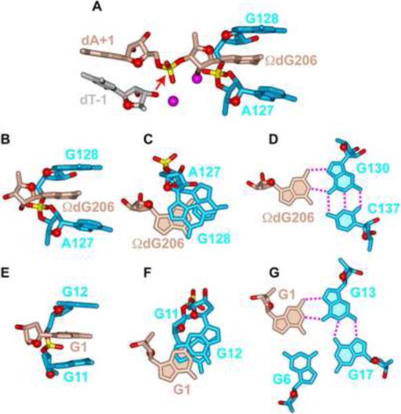
Figure 6. Comparison of a Guanosine Intercalated Between the G-G step in Azoarus Group I Intron and in the chl1 intronic G-Quadruplex.
(A) The G-binding motif in the crystal structure of the Azoarcus Group I intron (Adams et al., 2004). Note that partial intercalation of ΩdG206 between A127 and G128 assists in positioning the phosphate between ΩdG206 and dA+1 for in-line attack by the 2'-OH of dT-1 (designated by a red arrow). The scissible phosphate is flanked by Mg2+ cations shown as magenta balls. Phosphorus and oxygen atoms are colored in yellow and red, respectively. (B) Side and (C) look-down views of the intercalation of ΩdG206 between a G-G step and (D) hydrogen-bonding of Watson-Crick edge of ΩdG206 with Hoogsteen edge of G130 in the crystal structure of the Azoarcus Group I intron (Adams et al., 2004). (E) Side and (F) look-down views of the intercalation of G1 between the G11-G12 step and (G) hydrogen-bonding of Watson-Crick edge of G1 with Hoogsteen edge of G13 in the NMR-based solution structure of the chl1 intronic G-quadruplex reported in this study. (H) The postulated in line attack by a 3′ -OH on the scissible phosphate is shown by an arrow. Phosphorus and oxygen atoms are colored in yellow and red, respectively.

