Abstract
We demonstrate that laser beams can be converged toward a light-absorbing target through optically diffusive media by using photoacoustic-guided interferometric focusing. The convergence of light is achieved by shaping the wavefront of the incident light with a deformable mirror to maximize the photoacoustic signal, which is propor tional to the scattered light intensity at the light absorber.
Convergence of light toward a desired location in optically diffusive and aberrative media is a subject of great interest with regard to optical methods of biomedical imaging, where inhomogeneous media with some degree of opacity are generally present. A promising approach toward delivering a focused laser beam through scattering media by the use of interferometric focusing was recently demonstrated [1–4]. With interferometric focusing, a coherent beam can be made to focus at a chosen position by spatially shaping the wavefront to achieve constructive interference at the target. Liquid crystal spatial light modulators with hundreds to thousands of pixels have been used for wavefront shaping. The wavefront shaping process needs a feedback mechanism that monitors the intensity of the scattered light at the desired focal point. In previous studies, the intensity distribution was monitored by a camera placed behind the sample or by detecting the emissions from fluorescent probes embedded in the sample.
In this Letter, we demonstrate the feasibility of converging light through optically diffusive media toward an optically absorbing target using photoacoustic-guided interferometric focusing. In our study, the feedback mechanism that guides the wavefront shaping process is provided by the photoacoustic signal [5,6]. The generation of the photoacoustic signal is based on stress transients caused by rapid thermal expansion of the medium after absorbing a short (of the order of 1 ns) light pulse. This rapid thermal expansion generates a broadband acoustic pulse, which can be detected by an ultrasound transducer. Since the ultrasound signal is much less scattered than light, the absorption-based signal thus provides a noninvasive way of monitoring the intensity distribution of scattered light from the same side as the incident laser beam, obviating the need of placing a detector behind the sample. We demonstrate that, by maximizing the amplitude of the photoacoustic signal through wavefront shaping with a deformable mirror, the distorted and scattered laser beam can be reconverged toward an absorbing target, which can be an area defined by the focus of the ultrasound transducer or an isolated micrometer-sized light absorber. Delivery of focused laser beams deeper into media may find applications in image-guided intervention and, when used in conjunction with other optical imaging techniques, may facilitate optical imaging at greater depths.
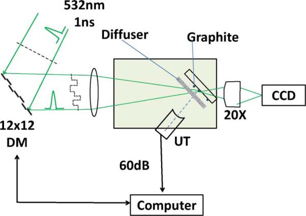
The schematic of the experimental setup is shown in Fig. 1.
Fig. 1.
(Color online) Schematic of experimental system. DM, deformable mirror; UT, ultrasound transducer. The diffuser, when introduced, is placed at 2 mm in front of the graphite absorber.
A frequency-doubled passively switched Cr,Nd:YAG laser emitting at 532 nm was used as the light source [7]. The laser generated 1 ns pulses at a repetition rate of 100 Hz. The deformable mirror consisted of 140 (12 × 12 without corner elements) microelectromechanical mirrors (Boston Micromachines Corporation, USA) with a full aperture of 3:3 mm. The reflected laser beam was focused to the light-absorbing target at an incident angle of 60°. A camera with a microscope objective was in line with the incident laser beam to verify the intensity distribution in the sample plane. The ultrasound transducers had center frequencies at 40 MHz or 75 MHz and a focal length of 1:2 cm, and the ultrasound beam axis was perpendicular to the sample plane. Both the sample and the transducer were placed in a distilled water bath. The photoacoustic signal from the transducer was amplified by 60 dB, and the peak-to-peak amplitude was recorded and averaged six times by a digital oscilloscope. The data were then processed by a computer that also controlled the operation of the deformable mirror. Measurements of the photoacoustic signal were performed for axial mirror displacements of a single pixel to create round trip phase delays of reflected light from 0 to 2π in 40 steps. After each scan, the mirror displacement was set to the value that gave rise to the maximum photoacoustic signal before advancing to the next pixel.
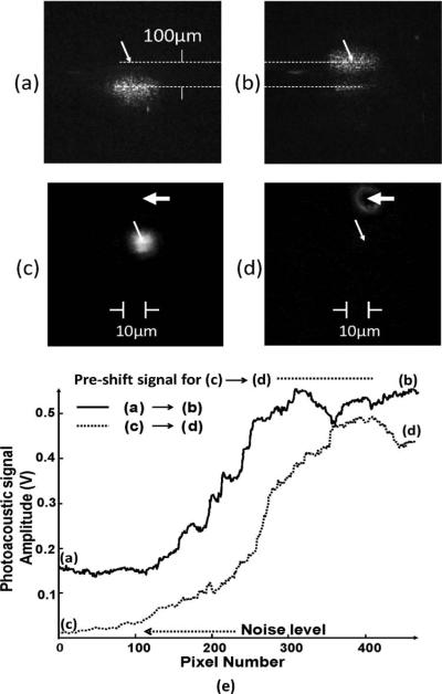
Photoacoustic-guided movement of a laser beam was first demonstrated in clear water. The laser beam was focused to a 40 μm spot on the surface of a typewriter carbon tape with uniform light absorption over the entire surface. The ultrasound transducer (75 MHz center frequency and 41 μm beam diameter at focus) was first aligned with the focused laser beam to achieve maximum photoacoustic signal. The transducer focus was then moved laterally by 100 μm. The phase-shaping algorithm was then run pixel by pixel sequentially. After completing three iterations of phase shaping, the laser beam was recentered at the transducer focus. Figures 2(a) and 2(b) show the laser beam profiles as viewed through the highly scattering carbon tape before and after the wavefront shaping. Figure 2(e) shows the amplitude of the photoacoustic signal generated by the laser-illuminated area on the carbon tape as the pixels were scanned sequentially. The amplitude enhancement typically reached a steady state after two iterations. The need for more than one iteration to reach steady state is because, using the continuous sequential algorithm, the optimized positions of the pixels during the first iteration were obtained using a background reference that can be shifted by the optimization of the pixels later in the sequence. This finding is consistent with previous experimental and simulated results [4], which showed that more than one iteration was needed to achieve the maximum enhancement factor.
Fig. 2.
Profiles of laser beam as viewed through the carbon tape (a) before and (b) after being guided to the focus of the ultrasound transducer (marked by the arrows) by wavefront shaping. (c) Photo of graphite particle (marked by wide arrow) after being shifted to 10μm from the laser beam. (d) Refocused laser beam centered at the graphite particle after phase shaping. The narrow arrows mark the locations of the center of ultrasonic focus. The diameter of the ultrasound focus is 90 μm. (e) Time evolution of the amplitudes of the photoacoustic signal as the deformable mirrors undergo three iterations of phase shaping, each iteration scanning through 140 pixels. Also shown is the preshift signal level.
The tracking of an isolated micrometer-sized light absorber was demonstrated by using a light-absorbing sample consisting of graphite particles of 10 μm diameter sparsely distributed on the surface of a 1 mm-thick glass slide. The laser beam was focused to a 10 μm spot on the sample. The laser beam and the ultrasound transducer (40 MHz center frequency and 90 μm focus diameter) were first centered at the graphite particle to achieve maximum photoacoustic signal. The graphite particle was then shifted laterally by 20 μm from the focused laser beam, shown in Fig. 2(c), where the photoacoustic signal diminished to the level of background noise. The phase-shaping algorithm was then run to restore the photoacoustic signal. Figure 2(d) shows the profile of the laser beam refocused to the new location centered on the graphite particle. Since the algorithm repositioned the laser beam over the absorbing particle, the brightest area in the center of the laser spot was blocked by the particle. The amplitude of the photoacoustic signal generated by the graphite particle as the deformable mirror undergoes three iterations of phase shaping is shown in Fig. 2(e). Approximately 75% of the maximum (preshift) photoacoustic signal was recovered at the new site. In this experiment, the buildup of the photoacoustic signal started from background noise level. The noise equivalent laser pulse energy was 230 pJ.
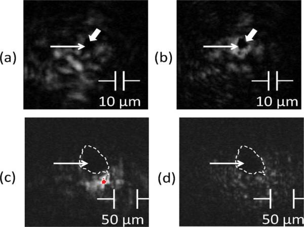
To introduce light scattering, a static diffuser consisting of two layers of paraffin (μa = 0.01 cm−1, μs = 203 cm−1, μs′ = 9.1 cm−1, g = 0.95, n = 1.42 at 532nm) of 0.25 mm thickness (0.5 mm total path length when oriented at 60°) were placed at 2 mm in front of the light-absorbing sample. The 75 MHz transducer has a focus diameter of 41 μm. Graphite particles of 10 μm and 50 μm nominal sizes were used to test the capability of refocusing for two different absorber sizes, one being an isolated small light absorber within the ultrasound focus, and the other being the size of the ultrasound focus. The cumulative effect of light scattering by the diffuser falls in the quasiballistic regime, where the diffuser thickness is greater than 1/μs and less than 1/μs′, meaning that light has sustained a few scattering events but retains a strong memory of the original incident direction [8]. Although the general propagation directions of light were retained, after an average of ten scattering events and an average scattering angle of 18° for each scattering event, the laser beam expanded tenfold and the wavefront was scrambled, as shown in Figs. 3(a) and 3(c). Photos of re-converged laser beams on graphite particles are shown in Figs. 3(b) and 3(d). Wavefront shaping resulted in a five-to tenfold enhancement of the photoacoustic signal, with the largest enhancement seen in the smaller graphite particle size.
Fig. 3.
(Color online) (a) Scattered laser beam after passing through paraffin films, (b) reconverged laser beam centered at the 10 μm graphite particle after wavefront shaping. The wide arrows mark the location of the graphite particle and the narrow arrows mark the location of the center of the ultrasound focus. (c) Scattered laser beam after passing through paraffin films with regions of overexposure in gray dot below dotted circle. (d) Reconverged laser beam centered at the 50 μm-diameter graphite particle after wavefront shaping. The dashed curves mark the contours of the graphite particle.
Although the brightest regions of the reconverged light shown in Figs. 3(b) and 3(d) were fully blocked by the graphite particles and the brightness could only be inferred by the enhancement of the photoacoustic signal, the reduction in light intensity in regions away from the graphite particles was clearly seen. Shadowing by the particle and the decreased light intensity of its surround are both indicative of light beam convergence upon the particle.
In the current setup, it took 20 min to complete three iterations or 3 s for each pixel of the deformable mirror to complete 40 steps of phase increment from 0 to 2π and, at each step, for the system to record and average six photoacoustic signals, and 7 min to scan 140 pixels sequentially. The dominating contribution for the long time to complete one scan in the current setup was the low repetition rate of the pulsed lasers. The maximum frame rate of the deformable mirror is 30 kHz. If a pulsed laser of repetition rate greater than 30 kHz were used and the electronics and software delay minimized, the framerate-limited time to complete one loop would be 2.8 s.
The sizes of the incident beam and the light absorber relative to the grain size of the speckle affect the achievable enhancement factor. In the present study, the size of the smallest grain of the speckle at 2 mm after the diffuser, from Fig. 3, was less than 2 μm. In order to produce a large enough photoacoustic signal for detection, the diam eter of the graphite particles was chosen to be about 10 μm. The size of the incident beam, limited by the focal length of the lens to avoid obstructing the ultrasound beam path in the current setup, was 10 μm. Thus both the incident beam and the graphite particles covered multiple transmission channels, and maximizing the signals in multiple channels simultaneously was known to lead to smaller enhancement factors compared to the theoretical values [3]. Initiation of phase optimization is also affected by the number of speckle grains within the sampling area. When the sampling area is much larger than the grain size of the speckle, the phase variation of the incident beam results in a spatial redistribution of the grains without causing a detectable change in the photoacoustic signal. This situation occurred when the graphite particles were in direct contact with the back surface of the diffuser, where the speckle grain size was less than 1 μm and no appreciable enhancement was detected. The use of a higher frequency transducer, which has a smaller focus spot, and a smaller incident beam size may allow this technique to be applied to smaller speckle sizes.
In conclusion, we have demonstrated experimentally that laser beams can be made to converge toward a light-absorbing target through optically diffusive media by using photoacoustic-guided interferometric focusing. This was achieved by maximizing the amplitude of the photoacoustic signal generated at the location of the intended point of convergence through wavefront shaping.
Acknowledgments
This work was supported by grant RR03037 from the National Center for Research Resources, which is a component of the National Institutes of Health (NIH), and, in part, by an unrestricted grant to the Department of Ophthalmology, Columbia University, from Research to Prevent Blindness, Inc.
References
- 1.Vellekoop IM, Mosk AP. Opt. Lett. 2007;32:2309. doi: 10.1364/ol.32.002309. [DOI] [PubMed] [Google Scholar]
- 2.Vellekoop IM, van Putten EG, Lagendijk A, Most AP. Opt. Express. 2008;16:67. doi: 10.1364/oe.16.000067. [DOI] [PubMed] [Google Scholar]
- 3.Vellekoop IM, Aegerter CM. Proc. SPIE. 2010;7554:755430. [Google Scholar]
- 4.Vellekoop IM, Mosk AP. Opt. Commun. 2008;281:3071. [Google Scholar]
- 5.Oraevsky AA, Jacques SL, Tittel FK. Appl. Opt. 1997;36:402. doi: 10.1364/ao.36.000402. [DOI] [PubMed] [Google Scholar]
- 6.Kong F, Chen YC, Lloyd H, Silverman RH, Kim HH, Cannata JM, Shung KK. Appl. Phys. Lett. 2009;94:033902. doi: 10.1063/1.3073749. [DOI] [PMC free article] [PubMed] [Google Scholar]
- 7.Zhou S, Lee KK, Chen YC, Li S. Opt. Lett. 1993;18:511. doi: 10.1364/ol.18.000511. [DOI] [PubMed] [Google Scholar]
- 8.Wang LV, Wu H-I. Biomedical Optics: Principles and Imaging. Wiley; 2007. [Google Scholar]


