Abstract
Background
The EOS™ X-ray machine, based on a Nobel prize-winning invention in physics in the field of particle detection, is capable of a simultaneous capture of biplanar X-ray images by slot scanning of the whole body in an upright, physiological load-bearing position, using ultra-low radiation doses. The simultaneous capture of spatially calibrated anterioposterior and lateral images provides a three-dimensional (3D) surface reconstruction of the skeletal system using a special software. Parts of the skeletal system in X-ray images and 3D-reconstructed models appear in true 1:1 scale for size and volume, thus spinal and vertebral parameters, lower limb axis lengths and angles, as well as any relevant clinical parameters in orthopaedic practice can be very precisely measured and calculated. Visualisation of 3D reconstructed models in various views by sterEOS 3D software enables presentation of top view images to help analyse rotational conditions of lower limbs, joints and spine deformities in the horizontal plane, providing revolutionary novel possibilities in orthopaedic surgery, especially in spine surgery.
Approach and conclusions
Our department has been extensively using the very first commercially available EOS™ imaging system worldwide for routine orthopaedic diagnostics since June 2007. During this period of about 4.5 years, more than 5,700 standard examinations have been carried out, about a third of them in spine deformity cases and the rest in lower limb orthopaedic cases. In this mini-review, general principles and uses of this groundbreaking integrated orthopaedic solution is reviewed with a few highlighted examples from our own clinical practice.
Introduction
Georges Charpak received the Nobel Prize in Physics in 1992 for his research in the field of particle detection, for the invention of the proportional multiwire chamber and gaseous X-ray detector [1]. The most widely used method of modern particle detection is the measurement of the number of electrons separated from atoms after collision with elemental particles (for example, the X-ray’s photons), so-called measurement of ionization. If ionization happens in a special gaseous mixture, the X-ray photons break off electrons from gas atoms, whose number is proportional to the kinetic energy of the photons. These freed electrons are accelerated in an electronic field and collide with further gas atoms from which a large number of additional electrons are broken off, sharply elevating a detectable number of electrons. The electron beam generated by the avalanche effect creates electrical discharges in a system consisting of numerous thin wires stretched alongside each other. This complicated grid system forms a typical proportional multiwire chamber that provides a uniform electronic field needed for the collection of electrons. In this way a proportional wire chamber is not only capable of counting the particles but it is also able to show the level of orbit they are spinning [2, 3].
This new X-ray detection method, while highly sensitive up to the level of a single photon, is unaffected by scattered radiation. This feature has created the opportunity to develop a new radiodiagnostic device, which can significantly reduce X-ray exposure while improving the quality of captured X-ray images. Use of this new technology has enabled the creation of higher quality images with a wider dynamic range, resulting in images with distinct gray shades increased to 30–50 thousand as opposed to traditional X-ray images with only a few hundred. Moreover, it also produces images with higher contrast and sharpness, i.e., image pixel resolution increased to 254 μm. The full-digital image processing creates an opportunity similar to the process of “windowing” in computed tomography (CT) when images are digitally enhanced after processing to only show a predefined range of grays better suited to radiation absorption characteristics of the examined organs or to user’s interest [4].
An X-ray device incorporating this new detection technology has been developed consisting of two co-linked pairs of a 45-cm wide linear radiation source and detector which are placed perpendicular to each other, in frontal and lateral positions (Fig. 1). Inside this X-ray imaging device, called EOS™ 2D/3D, biplanar X-ray images are simultaneously captured by the synchronised vertical movement of two pairs of X-ray tube and detector. During this vertical movement, a 170 cm high and 45 cm wide area is covered, resulting in high quality, high contrast anteroposterior (AP) and lateral (LAT) X-ray images within just ten to 25 seconds [5, 6] (Fig. 2).
Fig. 1.
Operational principles of the EOS™ 2D/3D system. Perpendicularly placed, vertically moving, co-linked units of X-ray tubes producing very thin collimated X-ray beams collected by unique line detectors with Nobel Prize winning technology result in simultaneously captured biplanar digital images of a patient in a standing, weight-bearing position. (Illustration used with permission from EOS Imaging, Paris, France)
Fig. 2.
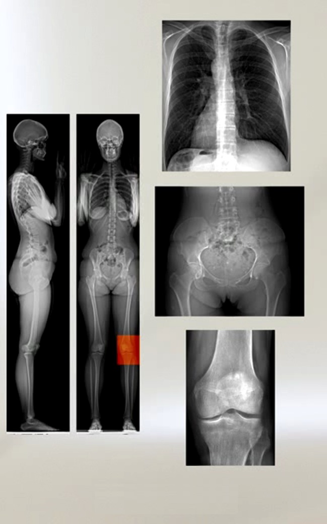
Two-dimensional digital X-ray images captured by the EOS™ 2D/3D system. From left to right and top to bottom: full-body biplanar lateral and posterioanterior (PA) images; PA thorax; PA pelvis; and PA right knee images. 1:1 scale, high contrast, high dynamic range, high resolution images free of distortion or artifacts. (Illustration used with permission from EOS Imaging, Paris, France)
The machine with two pairs of perpendicularly positioned radiation sources and detectors not only allows simultaneous capture of AP and LAT radiographs but also enables a precise three-dimensional (3D) reconstruction of vertebrae, pelvis and other parts of the skeletal system because images are captured in a spatially calibrated manner (Fig. 3). This 3D reconstruction is also a result of a new technical achievement, developed in collaboration by the Biomechanical Laboratory (Laboratoire Bioméchanique [LBM]) of the Arts et Métiers ParisTech in Paris, France and the Orthopaedic and Imaging Laboratory (Laboratoire de Reherche en Imagerie et d’Orthopédie [LIO]) of the École de Technologie Supérieure de l’Université du Québec in Montreal, Canada.
Fig. 3.
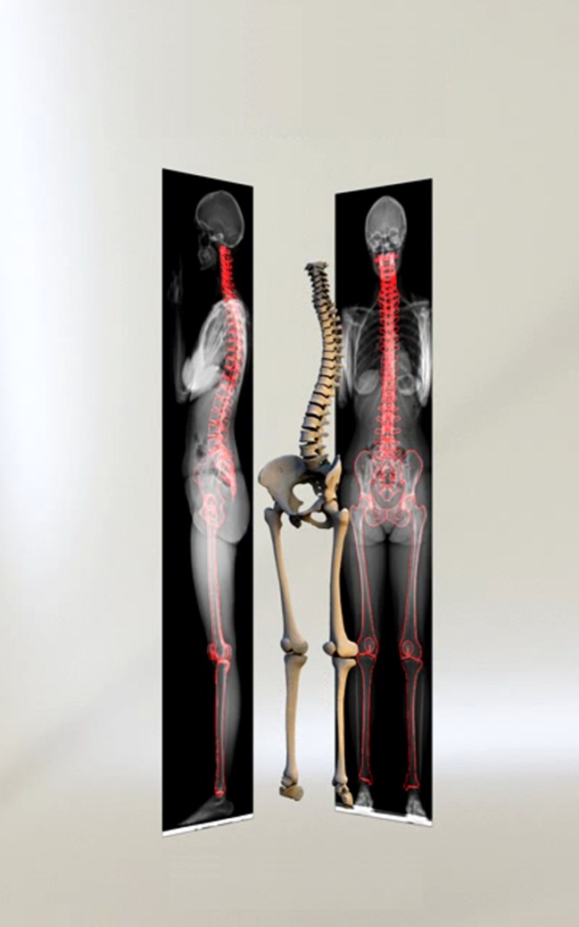
Full-body surface reconstructed 3D model based on an EOS™ 2D examination. Simultaneously captured, spatially calibrated biplanar X-ray images enable performing surface 3D reconstruction of the spine, pelvis and lower limb providing visual and parametric analysis of reconstructed 3D models. (Illustration used with permission from EOS Imaging, Paris, France)
The reconstruction procedure is based on the virtual and generic reconstruction of a normal human skeleton. The three-dimensional shape of bones in the virtual 3D skeleton was determined by 3D coordinates of specific points on the bone surface. Depending on the complexity of the shape, the number of points to accurately describe a 3D envelope of the respective bones varies from 400 to 9000. A significant reduction of these points can be achieved by using homothetic transformation, the rule of parallel resemblance, combined with complex statistical inferences, to define so-called reference points, which are minimally required to accurately determine the exact shapes of the bones. With these reference points, theoretical 3D models were created based on a series of 3D CT models and a statistical finite element models. One of the most complicated models is the spine, whose reference points and theoretical 3D model were created by measuring 1,628 individual vertebrae and reconstructing 96 individual spines in 3D [7, 8].
Visual information gained from simultaneously recorded AP and LAT X-ray images also makes it possible to identify reference points (for example, the geometric centre of the femoral head) in the X-ray images. Some reference points can be recognised in both AP and LAT X-ray images (so-called stereo-corespondents) and match specific anatomical references. Other reference points could be linked to a single anatomical reference but are only visible in one plane image and not in the other, therefore their precise localisation depends on the spatial orientation of the object.
Besides reference points, the bone contour (for example, the femoral head contour) can also be displayed by the generic 3D model, and overlaying the virtual model on both X-ray images is performed. Radiological contours and virtual bone contours do not necessarily overlap with each other in 3D. The virtual model can be modified by its reference points and contours, using non-linear deformations, translations or rotations as long as radiological and virtual bone contours match or until the virtual bone model best corresponds to the bone being modelled (Fig. 4).
Fig. 4.
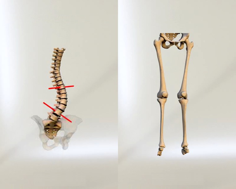
EOS™ 3D models of the spine with pelvis (left) and lower limbs with pelvis (right). Reconstructed 3D models can be displayed by a patented software in predefined standard planes (frontal, sagittal, horizontal) or freely rotated through 360° to present on-demand perspectives. Over 100 clinically relevant, 3D model-based angle and length measurements are automatically calculated and recorded. (Illustration used with permission from EOS Imaging, Paris, France)
The 3D reconstruction provided by EOS™ has been validated for various bones (vertebrae, femur, tibia) first using dried anatomical preparations in vitro, and then in vivo. In each case, a volumetric 3D reconstruction was performed based on CT images with 1-mm slices for limb parts and 2-mm slices for spine, and used as references. Surface 3D reconstruction was then used in the same patients and the same anatomical dummies with the EOS™, then the results of the two methods were compared.
The average difference was 0.9 mm with a maximal deviation of 2.4 mm in 95% of cases. In in vivo measurements the largest discrepancy was below 1.5 mm even in case of serious clinical deformities such as major scoliotic curves or severe knee arthritis, i.e., results were readily comparable with direct measurements based on 3D CT reconstructions of dried anatomical samples [9, 10]. Final results of all validation studies proved EOS™ 3D surface reconstructions equally accurate and readily corresponding to 3D CT reconstructions while using only a fraction of the radiation dose. Absorbed radiation dose by various organs during a full-body EOS™ 2D/3D examination required to perform a surface 3D reconstruction was shown to be 800–1000 times less than the amount of radiation during a typical CT scan required for a volumetric 3D reconstruction. With respect to the well-known adverse biological effects of ionizing radiation, advantages of using EOS™ are easily appreciated, especially in paediatric orthopaedic practice [11].
The most important practical advantage of EOS™ in daily routine work is the ability to produce high-quality full-body digital X-ray images, directly available for diagnostic purposes without further processing, by a single examination performed within ten to 25 seconds. To achieve identical results by conventional X-ray radiography, multiple exposure and image processing (such as stitching) are required, resulting in a significantly longer examination time with lower patient throughput and higher radiation dose per examination. Due to a significantly higher detector sensitivity and insensitivity to diffuse scattered radiation, image quality is dramatically enhanced, regardless of the body region examined. Another advantage is that captured images show objects in 1:1 scale, true-to-life size, without magnification and distortions, unfavourable effects in conventional radiography that were eliminated by line detection of double collimated X-ray beams and digital postprocessing of raw images. Further processing is optimised to the type of examination performed, with further possibilities for on-demand enhancements of grayscale range, and no need for repeated examinations. The system is DICOM compatible, i.e., captured images may be stored by standard digital radiology systems, and subsequently used or retrieved for 3D reconstructions in a dedicated digital workstation.
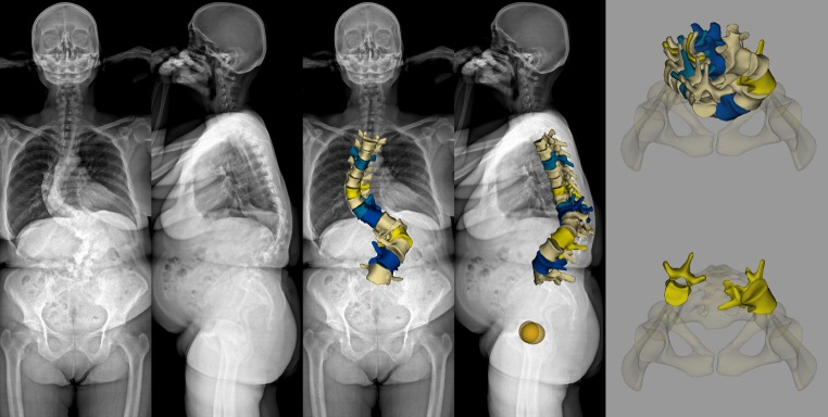
Another great advantage is the ability to produce surface 3D reconstructions with visual and quantitative parametric analysis of the skeletal system in a normal upright position. Presentation of EOS™ 3D reconstructions in various planar projections enables visualisation of the spinal geometry in the horizontal plane view from above (“top view”) that brings a revolutionary breakthrough in orthopaedic surgery, especially in scoliosis surgery (Fig. 5). EOS™ could be considered the only routinely available radiodiagnostical device today that allows 3D visualisation and analysis of a joint relative to its adjacent joints or to the skeleton as a whole. Concurrent examination of members forming a closed kynetic chain is also possible by EOS™ 3D reconstructions (Fig. 6). Analysis of relative 3D position and orientation of individual elements in a single joint under physiological loads can also be performed. EOS™ 3D presents the unique option of horizontal plane top-view images of the whole skeleton or parts of it, and this is the only solution for a realistic depiction of the skeletal system in 3D horizontal plane projection.
Fig. 5.
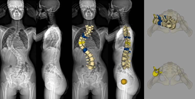
EOS™ 2D examination and sterEOS 3D reconstruction of the spine in adolescent idiopathic scoliosis. A 14-year-old girl with a history of scoliotic deformity treated in a brace for seven years. She reached menarche 6 months earlier and was referred to our department for a decision on corrective surgery. Biplanar EOS™ 2D images (image 1-2 from left) reveal a severe scoliotic deformity showing a large right convex thoracic curve (92° Lenke type 1A). The anterioposterior image shows the upper torso decompensated to the right with normal pelvic position. A rib hump is apparent and the sagittal curvature seems to be flattened (Th4-Th12 kyphosis 24°; L1-L5 lordosis 43°) in the lateral X-ray. The EOS™ 3D reconstructed spine model overlayed on the X-ray images (image 3-4 from left) demonstrates the 3D depiction of the deformity in the frontal and sagittal plane. End-vertebrae Th6 and Th12(blue) and apical vertebra Th9 (yellow) of the thoracic curve are highlighted in colour. The horizontal plane top view of the 3D spine model with the pelvis (upper right image) shows position and axial rotation of vertebrae relative to each other and the pelvis. Apical vertebra Th9 (yellow) could be individually visualised with the pelvis (bottom right image) to demonstrate its positional (lateral translation reaching to the right acetabulum) and axial rotational (38°) attributes
Fig. 6.
EOS™ 2D examination and sterEOS 3D reconstruction of the spine in adult degenerative scoliosis. A 59-year-old female patient with a history of degenerative lumbar spine deformity diagnosed five years earlier, causing low back pain and sciatica in her right upper leg. Anterioposterior and lateral EOS 2D images (image 1-2 from left) show a degenerative scoliosis consisting of a large left convex thoracolumbar curve with a significant apical vertebral rotation and a right convex thoracic curve. The upper body seems to be compensated and the pelvis position appears normal. EOS™ 3D reconstructed spine model of spine region Th4-L5 overlayed on the X-ray images (image 3-4 from left) demonstrates the 3D depiction of the deformity in frontal and sagittal plane. End-vertebrae Th5, Th11(azure) and apical vertebra Th8 (yellow) of the 90° thoracic curve and end-vertebrae Th12, L4 (blue) and apical vertebra L2 (yellow) of the 110° thoracolumbar curve are highlighted in colour. Sagittal curves appear abnormal with an apparent angular kyphosis of the lumbar region (L1-L5 lordosis -4°). Relative lateral deviations and rotational changes of vertebrae are more apparent in the horizontal plane top view image showing the reconstructed 3D spine model with the pelvis (upper right). Axial rotation of apical vertebrae L2 and Th8 (53° and −20°, respectively) with their lateral translation and relative position are more conclusive when visualised individually with the pelvis (bottom right)
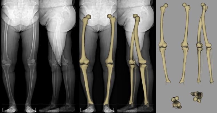
Since EOS 2D images and 3D surface reconstructed models present skeletal objects in their true, 1:1 scale size and volume, lengths and angles of extremities, axial rotation and torsion of spinal vertebrae or lower limb components, physiological spinal curves such as kyphosis and lordosis scoliotic spine deformities, and all relevant orthopaedic clinical parameters are automatically calculated and recorded (Fig. 7) [12]. Horizontal plane rotational aspects of the whole skeletal system are readily visualised and evaluated in top-view images. Length discrepancies caused by abnormal pelvic position, rotational changes of lower limbs, as well as shoulder position or rotational asymmetry could be detected and underlying circumstances and causes analysed.
Fig. 7.
EOS™ 2D examination and sterEOS 3D reconstruction of the lower limbs in adult degenerative knee arthritis. A 72-year-old female patient with a history of right knee problems showing an increasing pain in the last two years. Physical examination revealed antalgic gait with a limp, 10° flexion contracture, 15° varus position, knee flexion reduced to 110° and subpatellar crepitation. Biplanar EOS™ X-ray images (image 1-2 from left) demonstrate spondylosis and spondylarthritis in visible parts of the lumbar spine, intermediate arthritic aberrations of the hips and both knees with emphasis in the medial compartment and lateralisation of both patella. Apexes of patellae are spiculated and osteophytes are visible in both femoropatellar surfaces. Varus position of the right knee is more apparent. EOS™ 3D reconstructed 3D models of the lower limbs overlayed to the X-ray images (image 3-4 from left) and shown in frontal, sagittal and horizontal plane top views (image 5-6-7 on the right) resulted in the following relevant clinical parameters: knee varus – right: 13°, left: 6°; femoral mechanical angle – right: 87°, left: 92°; tibial mechanical angle – right: 82°, left: 87°; HKS angle – right: 4.0°, left: 6.0°
Changes in 3D balance of body posture during life, for example, in elderly, could be quantified and monitored.
Also, 3D visualisation, evaluation and follow-up of postoperative results after orthopaedic surgical interventions or effects of conservative treatment could be performed.
The EOS™ system has opened a new era in three-dimensional evaluation of orthopaedic diseases affecting the entire skeletal system or individual components thereof, either in adults or in children. It has enabled capture of full-body 2D radiographs in upright normal loads with significantly reduced radiation dose. It has helped to re-focus attention to three-dimensional characteristics of skeletal diseases, and has emphasised the utmost importance of three-dimensional evaluation of pathological changes in the skeletal system, particularly in horizontal plane view, and especially in children and adolescents.
Acknowledgments
Conflict of interest
The authors declare that they have no conflict of interest.
References
- 1.The Nobel Prize in Physics (1992) Nobelprize.org. The official web site of the Nobel Prize. http://nobelprize.org/nobel_prizes/physics/laureates/1992/index.html. Accessed December 19, 2011
- 2.Charpak G. La détection des particules. Recherche. 1981;128:1384–1396. [Google Scholar]
- 3.Charpak G. Electronic imaging of ionizing radiation with limited avalanches in gases. Rev Mod Phys. 1993;6:591–598. doi: 10.1103/RevModPhys.65.591. [DOI] [Google Scholar]
- 4.Després P, Beaudoin G, Gravel P, et al. Evaluation of a full-scale gas microstrip detector for low-dose X-ray imaging. Nucl Instr Meth Phys Res A. 2005;536:52–60. doi: 10.1016/j.nima.2004.07.169. [DOI] [Google Scholar]
- 5.Dubousset J, Charpak G, Dorion I, et al. Le system EOS nouvelle imagerie osteo-articulaire basse dose en position debout. E-mémoire de l’Académie National de Chirugie. 2005;4:22–27. [PubMed] [Google Scholar]
- 6.Dubousset J, Charpak G, Dorion I, et al. A new 2D and 3D imaging approach to musculoskeletal physiology and pathology with low-dose radiation and the standing position: the EOS system. Bull Acad Natl Med. 2005;189:287–297. [PubMed] [Google Scholar]
- 7.Bras A, Laporte S, Mitton D, et al. 3D detailed reconstruction of vertebrae with low dose digital stereoradiography. Stud Health Technol Inform. 2002;91:286–290. [PubMed] [Google Scholar]
- 8.Bras A, Laporte S, Mitton D, et al. A biplanar reconstruction method based on 2D and 3D contours: application to the distal femur. Comput Methods Biomech Biomed Engin. 2003;6:1–6. doi: 10.1080/1025584031000065956. [DOI] [PubMed] [Google Scholar]
- 9.Mitton D, Landry C, Véron S, et al. A 3D reconstruction method from biplanar radiography using non-stereocorresponding points and elastic deformable meshes. Med Biol Eng Comput. 2000;38:133–139. doi: 10.1007/BF02344767. [DOI] [PubMed] [Google Scholar]
- 10.Mitulescu A, Semaan I, Guise JA, et al. Validation of the non-stereo corresponding points stereoradiographic 3D reconstruction technique. Med Biol Eng Comput. 2001;39:152–158. doi: 10.1007/BF02344797. [DOI] [PubMed] [Google Scholar]
- 11.Kalifa G, Charpak G, Maccia C, et al. Evaluation of a new low-dose digital x-ray device: first dosimetric and clinical result in children. Pediatr Radiol. 1998;28:557–561. doi: 10.1007/s002470050413. [DOI] [PubMed] [Google Scholar]
- 12.Than P, Szuper K, Somoskeöy S et al (2011) Geometrical values of the normal and arthritic hip and knee detected with the EOS imaging system. Int Orthop (SICOT). doi:10.1007/s00264-011-1403-7 [DOI] [PMC free article] [PubMed]


