Abstract
Purpose
Medial femoral neck fractures are common, and closed reduction and internal fixation by three cannulated screws is an accepted method for the surgical treatment. Computer navigation for screw placement may reduce fluoroscopy time, the number of guidewire passes and optimise screw placement.
Methods
In the context of a sawbone study, a computer-assisted planning and navigation system based on 3D-imaging for guidewire placement in the femoral neck was tested to improve screw placement. Three screws were inserted into 12, intact, femoral sawbones using the conventional technique and into 12, intact, femoral sawbones guided by the computer-based navigation system. Guidewire and subsequent screw placement in the femoral neck were evaluated.
Results
Use of the navigation system resulted in a significant reduction of the number of drilling attempts (p ≤ 0.05) and achieved optimised accuracy of implant placement by attaining significantly better screw parallelism (p ≤ 0.05) and significantly enlarged neck-width coverage by the three screws (p ≤ 0.0001). Computer assistance significantly increased the number of fluoroscopic images (p ≤ 0.001) and the operation time (p ≤ 0.0001).
Conclusions
Three-dimensional computer-assisted navigation improves accuracy of cannulated screw placement in femoral neck while increasing the number of fluoroscopic images and operation time. Additional studies including fractured sawbones and cadaver models with the goal of reducing operation time are indispensable before introduction of this navigation system into clinical practice.
Introduction
Surgery in patients with hip fractures is increasing with the large demographic growth of geriatric patients [1]. Closed reduction and internal fixation with three screws forming a triangle is an accepted method for the surgical treatment of medial femoral neck fractures [2]. Exact screw placement with a greater distance between the screws enables a biomechanically stable fixation. The number of drill attempts should be kept to a minimum as they might weaken the cortical and cancellous bone and might lead to subtrochanteric fractures [3]. Furthermore, extra passes are time consuming and may penetrate the articular surface of the femoral head. Despite good results using this technique, incorrectly positioned screws and secondary fracture dislocations have been described in 10–50% [4, 5]. C-arm fluoroscopy is the standard imaging used to guide percutaneous guide wire and subsequent screw placement. Extensive use of fluoroscopy may endanger the patient and the operating room staff, while repeated rotation of the C-arm endangers sterility [6, 7].
Mobile C-arms with three-dimensional imaging allow for intraoperative 3D visualisation of anatomical areas. Iso-C 3D mobile C-arm (Siemens AG, Medical Solutions, Erlangen, Germany) has equal clinical value to spiral computed tomography but is superior in comparison to two-dimensional imaging [8, 9]. In combination with computer-based navigation surgeons are able to place implants very precisely (for example, for pedicle screw placement or for screws placed in the acetabulum or the sacroiliac joint) while having a simultaneous real-time three-dimensional view of the osseous anatomy of the patient [10–12].
We postulated that three-dimensional computer-assisted navigation would reduce the number of drilling attempts, the number of fluoroscopic images and the operating time while optimising the precision of hip screw placement compared to the conventional fluoroscopy-based technique.
Materials and methods
Experimental setup
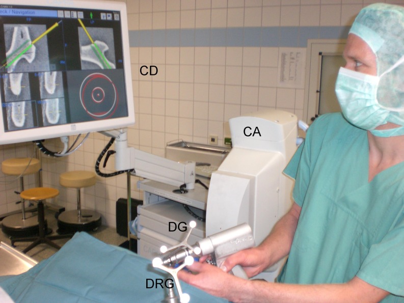
Twenty-four identical intact left femoral plastic femurs (Sawbones®, Malmö, Sweden) were used to simulate reduced medial femoral neck fractures. All femurs were mounted on a bench clamp. For percutaneous screw placement, a surgical drape imitated soft tissue coverage. In this way, the surgeon was prevented from using macroscopic anatomical landmarks for orientation (Fig. 1). Three cannulated screws were inserted into 12 femoral necks guided by conventional fluoroscopic imaging (group 1) and into 12 guided by a three-dimensional computer-assisted navigation system (group 2). First, one surgeon (an orthopaedic consultant) performed the placement of three cannulated screws (8.0 mm, DePuy®, Kirkel-Limbach, Germany) into the femoral neck of 12 Sawbones® in accordance with the manufacturer’s recommended technique using the conventional two-dimensional fluoroscopic imaging (group 1). Second, the same surgeon performed the placement of the three cannulated screws into 12 Sawbones® guided by the three-dimensional computer-assisted navigation system (group 2). The computer-assisted technique used the CAPPA C-Nav navigation system (CAS Innovations®/Siemens, Erlangen, Germany) in combination with the three-dimensional mode of the C-arm fluoroscope (ARCADIS Orbic 3D®, Siemens, Erlangen, Germany).
Fig. 1.
Operative set-up with the image-guided freehand navigation of the guide wire into the femoral neck using the CAPPA C-Nav navigation system (CAS Innovations/Siemens, Erlangen, Germany). CD image seen on the computer display, DG calibrated guidewire tracker, DRG dynamic reference base, CA C-arm fluoroscope
Surgical technique (conventional)
For conventional screw placement, the surgeon used a C-arm fluoroscope (ARCADIS Orbic 3D®, Siemens, Erlangen, Germany) in conventional two-dimensional mode. Using a power drill, a guide wire (Kirschner wire; diameter, 3.2 mm) was gradually advanced using a cannulated single drill guide under optimal image intensification in two planes until the subchondral bone of the femoral head was reached. It was placed cranial in the femoral neck. After measuring length, a cannulated drill bit was used to drill the appropriate canal. An 8.0-mm cannulated screw was then inserted over the guide wire. We performed this procedure for the caudal two screws in the same manner (first dorsal, second ventral) trying to form a triangle with two screws close to the anterior and posterior cortices near Shenton's arch. Afterwards, the guide wires were removed.
Surgical technique (navigated)
For computer-assisted insertion of cannulated screws a dynamic reference base (DRB) was fixed on the distal ventral part of the femur metaphysis using a Schanz screw. The surgeon executed the following three planning and navigation steps:
-
Step 1
Three-dimensional image acquisition
For three-dimensional image acquisition the C-arm was positioned isocentrically to the femoral neck, in both anteroposterior (AP) and lateral projections. This was confirmed by orthogonal lasers. By rotation of 190° around the proximal femur three-dimensional imaging was performed by calculating multiplanar reconstructions from 100 C-arm images that were registered during the automated rotating scanning procedure. With the high-resolution data set, a cube with a volume of approximately 12 cm3 was generated. During the scans, the surgeon left the operation room. After the scans were completed the images were transferred to the navigation system.
-
Step 2
Planning of screw alignment
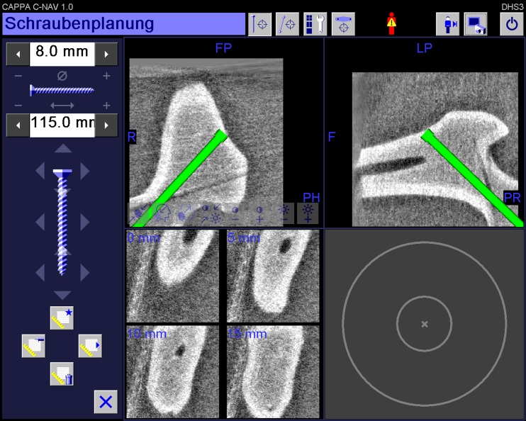
The positions of the three cannulated screws were then planned on the reconstructed three planes (anteroposterior, lateral and coronal plane) (Fig. 2). The goal of this planning step was to find valid implant positions forming a triangle with a maximum screw spread while avoiding femoral head or neck perforation.
-
Step 3
Navigation of the guide wire
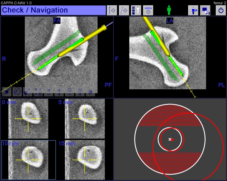
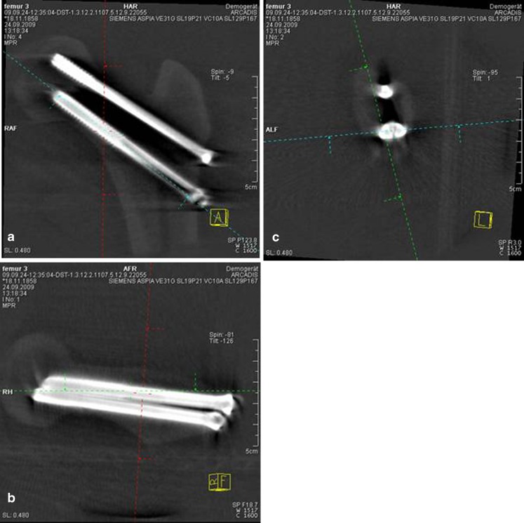
After the surgeon had defined satisfactory implant positions, image-guided navigation of the guide wire in the planned trajectories followed. For guide wire stabilisation, a non-navigated drill guide was used. For placement of the guide wire in the femoral neck and head, the optical tracking system permanently tracked the position of the calibrated drilling machine together with the rigidly fixed dynamic reference base of the femur. Three-dimensional reconstructions with a virtual projection of the navigated guide wire in relation to the femur and cross-hair navigation enabled plausibility checking (Fig. 3). After guide wire placement, cannulated screws were placed in the same fashion as in the conventional technique. After screw insertion, another three-dimensional scan with 100 C-arm images confirmed screw placement (Fig. 4a–c).
Fig. 2.
Planning of the screw position in the femoral neck. The length and diameter of the screws are measured and displayed on the left part of the display
Fig. 3.
Visualisation of the image-guided freehand navigation of the guide wire in the planned trajectory. Display of two cross-hair-like vectors for orientation of the navigation tool on the right lower part of the display. The small, inner circle represents the position of the guide wire tip; the larger, outer circle represents the position of a point on the guide wire axis. The inner and the outer circle in the centre means that the tool is aligned. Note the representation of the depth of the distance ahead of the guide wires tip on the left lower part of the display
Fig. 4.
Screenshots of the final implant position after the three-dimensional confirmation scan in the (a) anteroposterior, (b) lateral and (c) coronal plane
Data collection
During each procedure, the following measurements were recorded:
-
Drilling attempts
Every correction of the angle, including backward movement of the drill, was counted as a drilling attempt.
-
Implant placement accuracy.
Screw parallelism and the neck-width coverage (the triangular area [mm2] of the femoral neck held by screws was calculated by the distances of the three screws measured from the centre of each screw) were determined. According to the evaluation of Hamelinck et al. [13] the angle between the screws was documented, and the points were awarded for the angle of placement in two directions according to the following scale:- 4 points for 0–3° deviation, 2 points for 3–6° deviation, and 0 points for 6° or greater deviation.
- All three screws were compared with each other.
-
Fluoroscopic images
The total number of fluoroscopic single shots was counted.
-
Operation time
The total duration of operative time was taken from the moment of inserting the first guide wire (group 1) or from fixation of the dynamic reference base (group 2), respectively, until the three screws were finally positioned.
The analysis was performed by one investigator, who was blinded to the technique used and presented with the images in a random order.
Statistical methods
For statistical analysis we used the paired Student t-test. Values are presented as mean±standard deviation (SD). All tests applied were two-tailed, and p values ≤0.05 were considered statistically significant. Evaluation was carried out using the statistics program Instat 3 for Windows XP.
Results
Neither in the group using the conventional technique (group 1) nor the group using the three-dimensional computer-assisted technique (group 2) did the procedure have to be interrupted at any time or in any case. In all 24 cases, placement of the guide wire in the femoral neck and head and subsequent placement of three cannulated screws were successful. The results of the individual measurements are presented in Table 1.
Table 1.
Measurements of the conventional fluoroscopic technique (group 1) and the three-dimensional computer-assisted technique (group 2). The values are given as the mean and the standard deviation. Statistical significance was defined for *p ≤ 0.05; **p ≤ 0.0001
| Measurement | Group 1 | Group 2 |
|---|---|---|
| Drilling attempts (no.) | 4.8 ± 1.6 | 3.0 ± 0* |
| Precision: screw parallelism (points) | 22.5 ± 1.5 | 24 ± 0* |
| Precision: triangular area (mm2) | 54.8 ± 10.2 | 70.8 ± 5.1** |
| Fluoroscopic single shots (no.) | 24.8 ± 9.1 | 200 ± 0** |
| Total operation time per procedure (min) | 15.9 ± 2.7 | 38.3 ± 4.3** |
The number of fluoroscopic single shots taken to achieve an acceptable position of all screws was significantly increased when using computer-assistance (p ≤ 0.001). Using the computer-guided system three drilling attempts were necessary for implant placement in all cases, while significantly more drilling attempts were used in the conventional technique (p ≤ 0.05). Implant placement was significantly more accurate using the navigation system as screw parallelism was significantly more precise (p ≤ 0.05) and the neck-width coverage significantly enlarged (p ≤ 0.0001). Computer assistance significantly increased the mean operation time (p ≤ 0.0001).
Discussion
To our knowledge, this is the first publication reporting the outcomes of three-dimensional computer-assisted navigation for percutaneous hip screw placement.
Drilling attempts
This study shows that the first-pass accuracy for guide wire placement in the femoral neck was improved using the computer navigation system. The drilling attempts were reduced to the minimum of three required to place the cannulated screws. The surgeon could trust the navigation system. This speaks in favour of this technique and may be regarded as an important advantage of three-dimensional computer-assisted insertion of cannulated hip screws. In clinical use, this may minimise revision surgery caused by early failure of implant fixation in a weakened femoral neck or early osteoarthritis caused by penetration of the femoral head. In comparison to authors who performed biplanar computer-assisted guide wire placement in the femoral neck, the results are similar [13–16]. In these studies, one of 15 computer-assisted trials required a second pass because the surgeon did not follow the computer plan [14].
Implant placement accuracy
It was found that screw parallelism was significantly improved and neck-width coverage significantly enlarged with computer navigation. This has been shown to improve stability of fracture fixation [2, 17]. Furthermore, computer navigation enables more constant screw placement as the SD of neck-width coverage is minor compared to the conventional technique. This procedure might be of interest in dysplastic femoral necks due to the advantage of 3D illustration of the proximal femur. Use of a mechanical parallel drill guide was avoided. In clinical application this may result in an enlarged skin incision due to bone approximation and screw spread might be restricted due to the holes provided. In the few studies reporting results of navigated cannulated hip screw placement, data concerning screw placement accuracy differ [13, 18, 19]. While Liebergall et al. [18] also improved screw parallelism and neck-width coverage using the iON FluroNavStealthStation (Medtronic SNT, Louisville, Colorado) navigation system®, Kendoff et al. [19] and Hamelinck et al. [13] found that screw placement could not be improved using the Vector Vision® (Brainlab, Heimstetten, Germany) system. Due to different setups (sawbone [13, 19], cadaver [19] and clinical [18] setup), different navigation systems used and the small number of navigated femurs, results can hardly be compared.
Fluoroscopic images
Using the three-dimensional computer-assisted navigation technique, the number of fluoroscopic shots increased more than seven times compared to the conventional technique. The radiation load of one scan using 100 fluoroscopic images is comparable to one computed tomography scan [20]. In clinical application, the use of fluoroscopy is a concern to the patient, particularly to the radiosensitive reproductive organs which are close to the proximal femur [21]. For the operating team, the radiation dose is reduced compared to the conventional method, as the navigation system allows them to keep a distance from the C-arm during image acquisition. Surgeons might reduce irradiation, as the automated rotating scanning procedure is standardised, and suboptimal so called “test-X-rays” to achieve an optimal view on the proximal femur in the two planes, can be avoided. Using the navigation system wrong pathways of the guide wire were corrected “online” and no confirmatory fluoroscopic images were needed until the final implant position had been achieved. After the first scan, further rotation of the C-arm was not necessary with computer navigation. In a clinical setting, this might improve sterility as this procedure could be performed unsterile before the operation starts. Furthermore, a second scan could be avoided as X-rays in anteroposterior and lateral planes usually suffice to check implant placement postoperatively.
Operation time
Fluoroscopic image acquisition supported by three-dimensional computer-assisted navigation is a time consuming process which at least doubles operation time. In our setting, the surgeon himself performed the three planning and navigation steps. Tracking the position of the drilling machine in relation to the dynamic reference base requires a learning process. With further development and an additional surgeon performing the planning steps, the operative time might be reduced.
Limitations
This study showed some limitations. There were no variations of the configuration and size of the sawbones. As just one surgeon performed all operations, increasing experience of the surgeon during guidewire and subsequent screw placement could not be avoided. Therefore, supplementary ex-vivo cadaver studies investigating the use of the navigation system in femurs with physiological variation in the dimension and configuration of the proximal femur are desirable. One weakness of this study is the use of intact sawbones. The proposed system is only capable of tracking one bone fragment since only one DRB is used for the distal part of the femur. Navigated reduction of the two fracture fragments would be desirable and is planned for future approaches. Future developments should also concentrate on the development of DRB fixation methods that provide a rigid but minimally invasive fixation to the bone. Noninvasive reference technology using bonding sheets, clamp fixation or external bands could not fulfil the requirements. Therefore, invasive fixation techniques using Schanz screws are currently still the method of choice [22]. It remains to be seen, whether the 3D dataset in the cube with a volume of approximately 12 cm3 is large enough for implant planning. Future directions may facilitate implant planning by including digital flat-panel detectors generating an enlarged datacube with a volume of more than 12 cm3.
Another potential criticism is the fact that we only compared the number of fluoroscopic images between the conventional and the computer-assisted procedure. We did not measure the real reduction of the ionizing radiation exposure for the patient and the operation staff. The use of dosimeters to determine the individual exposure to ionizing radiation and the reduction achieved by the computer-assisted procedure should be taken into account for future studies.
Conclusion
Use of three-dimensional computer-assisted navigation for the placement of cannulated hip screws decreases the number of guide wire passes while optimising screw parallelism and enlarging neck-width coverage by the cannulated screws. Computer-assisted surgery with this system increases the operating time and the number of fluoroscopic images. Although these results are promising, additional laboratory studies including fractured sawbone-models and cadaver studies should be performed. The studies should focus on reducing the operating time prior to the introduction of the 3D navigation system into clinical practice.
Acknowledgements
This study has been funded by the German Federal Ministry of Education and Research (BMBF) within the framework of the research program OrthoMIT through grants BMBF 01EQ0802 and 01IBE02C.
Conflict of interest
The authors declare that they have no conflict of interest
References
- 1.Kannus P, Niemi S, Parkkari J, Palvanen M, Vuori I, Järvinen M. Hip fractures in Finland between 1970 and 1977 and predictions for the future. Lancet. 1999;353:802–5. doi: 10.1016/S0140-6736(98)04235-4. [DOI] [PubMed] [Google Scholar]
- 2.Selvan VT, Oakley MJ, Rangan A, Al-Lami MK. Optimum configuration of cannulated hip screws for the fixation of intracapsular hip fractures: a biomechanical study. Injury. 2004;35:136–41. doi: 10.1016/S0020-1383(03)00059-7. [DOI] [PubMed] [Google Scholar]
- 3.Kloen P, Rubel IF, Lyden JP, Helfet DL. Subtrochanteric fracture after cannulated screw fixation of femoral neck fractures: a case report of four cases. J Orthop Trauma. 2003;17:225–229. doi: 10.1097/00005131-200303000-00013. [DOI] [PubMed] [Google Scholar]
- 4.Lindequist S, Tornkvist H. Quality of reduction and cortical screw support in femoral neck fractures. An analysis of 72 fractures with a new computerized measuring method. J Orthop Trauma. 1995;9:215–21. doi: 10.1097/00005131-199506000-00006. [DOI] [PubMed] [Google Scholar]
- 5.Szita J, Cserhati P, Bosch U, Manninger J, Bodzay T, Fekete K. Intracapsular femoral neck fractures: the importance of early reduction and stable osteosynthesis. Injury. 2002;33:41–6. doi: 10.1016/S0020-1383(02)00330-3. [DOI] [PubMed] [Google Scholar]
- 6.Mehlman CT, DiPasquale TG. Radiation exposure to the orthopaedic surgical team during fluoroscopy: “how far away is far enough?”. J Orthop Trauma. 1997;11:392–8. doi: 10.1097/00005131-199708000-00002. [DOI] [PubMed] [Google Scholar]
- 7.Sanders R, Koval KJ, Pasquale T, Schmelling G, Stenzler S, Ross E. Exposure of the orthopaedic surgeon to radiation. J Bone Joint Surg [Am] 1993;75:326–30. doi: 10.2106/00004623-199303000-00003. [DOI] [PubMed] [Google Scholar]
- 8.Kendoff D, Citak M, Gardner MJ, Kfuri M, Jr, Thumes B, Krettek C, Hüfner T. Three-dimensional fluoroscopy for evaluation of articular reduction and screw placement in calcaneal fractures. Foot Ankle Int. 2007;28:1165–71. doi: 10.3113/FAI.2007.1165. [DOI] [PubMed] [Google Scholar]
- 9.Kotsianos D, Rock C, Euler E, Wirth S, Linsenmaier U, Brandl R, Mutschler W, Pfeifer KJ. 3-D imaging with a mobile surgical image enhancement equipment (ISO-C-3D). Initial examples of fracture diagnosis of peripheral joints in comparison with spiral CT and conventional radiography. Unfallchirurg. 2001;104:834–8. doi: 10.1007/s001130170054. [DOI] [PubMed] [Google Scholar]
- 10.Wendl K, Recum J, Wentzensen A, Grützner PA. Iso-C 3D assisted navigated implantation of pedicle screws in thoracic lumbar vertebrae. Unfallchirurg. 2003;106:907–13. doi: 10.1007/s00113-003-0683-9. [DOI] [PubMed] [Google Scholar]
- 11.Stöckle U, König B, Schaser K, Melcher I, Haas NP. CT and fluoroscopy based navigation in pelvic surgery. Unfallchirurg. 2003;106:914–20. doi: 10.1007/s00113-003-0677-7. [DOI] [PubMed] [Google Scholar]
- 12.Stöckle U, Schaser K, König B. Image guidance in pelvic and acetabular surgery—expectations, success and limitations. Injury. 2007;38:450–62. doi: 10.1016/j.injury.2007.01.024. [DOI] [PubMed] [Google Scholar]
- 13.Hamelinck HKM, Haagmans M, Snoeren MM. Safety of computer-assisted surgery for cannulated hip screws. Clin Orthop Rel Res. 2006;455:241–5. doi: 10.1097/01.blo.0000238815.40777.d2. [DOI] [PubMed] [Google Scholar]
- 14.Mayman D, Vasarhelyi EM, Long W, Ellis RE, Rudan J, Pichora DR. Computer-assisted guidewire insertion for hip fracture fixation. J Orthop Trauma. 2005;19:610–5. doi: 10.1097/01.bot.0000177106.30837.28. [DOI] [PubMed] [Google Scholar]
- 15.Suhm N, Beck T, Zuna I, Marazzi C, Staedele H, Jacob AL, Messmer P, Regazzoni P. Fluoroscopy-based surgical navigation versus fluoroscopic guidance to control guide wire insertion for osteosynthesis of femoral neck fractures. Eur J Trauma. 2004;1:23–28. doi: 10.1007/s00068-004-1267-2. [DOI] [Google Scholar]
- 16.Mueller MC, Belei P, Fuente M, Strake M, Weber O, Burger C, Radermacher K, Wirtz DC. Evaluation of a fluoroscopy-based navigation system enabling a virtual radiation-free preview of X-ray images for placement of cannulated hip screws. A cadaver study. Comp Aided Surg. 2011;16:22–31. doi: 10.3109/10929088.2010.542694. [DOI] [PubMed] [Google Scholar]
- 17.Gurusamy K, Parker MJ, Rowlands TK. The complications of displaced intracapsular fractures of the hip: the effect of screw positioning and angulation on fracture healing. J Bone Joint Surg Br. 2005;87:632–634. doi: 10.1302/0301-620X.87B5.15237. [DOI] [PubMed] [Google Scholar]
- 18.Liebergall M, Ben-David D, Weil Y, Peyser A, Mosheiff R. Computerized navigation for the internal fixation of femoral neck fractures. J Bone Joint Surg [Am] 2006;88:1748–54. doi: 10.2106/JBJS.E.00137. [DOI] [PubMed] [Google Scholar]
- 19.Kendoff D, Hüfner T, Citak M, Maier C, Wesemeier F, Pearle A, Krettek C. A new parallel drill guide for navigating femoral neck screw placement. Development and evaluation. Unfallchirurg. 2006;109:875–880. doi: 10.1007/s00113-006-1142-1. [DOI] [PubMed] [Google Scholar]
- 20.Rock C, Kotsianos D, Linsenmaier U, Fischer T, Brandl R, Vill F, Wirth S, Kaltschmidt R, Euler E, Pfeifer KJ, Reiser M. Studies on image quality, high contrast resolution and dose for the axial skeleton and limbs with a new, dedicated CT system (ISO-D-3D) Rofo. 2002;174:170–6. doi: 10.1055/s-2002-20107. [DOI] [PubMed] [Google Scholar]
- 21.Kwong L, Johanson PH, Zinar DM, Lenihan MR, Herman MW. Shielding of the patient’s gonads during intramedullary interlocking femoral nailing. J Bone Joint Surg [Am] 1990;72:1523–6. [PubMed] [Google Scholar]
- 22.Kendoff D, Bogojevic A, Citak M, Citak M, Maier C, Maier G, Krettek C, Hüfner T. Experimental validation of non-invasive referencing in navigated procedures on long bones. J Orthop Res. 2007;25:201–207. doi: 10.1002/jor.20318. [DOI] [PubMed] [Google Scholar]


