Abstract
This study integrates the hardware circuit design and the development support of the software interface to achieve a 32-channel EEG system for BCI applications. Since the EEG signals of human bodies are generally very weak, in addition to preventing noise interference, it also requires avoiding the waveform distortion as well as waveform offset and so on; therefore, the design of a preamplifier with high common-mode rejection ratio and high signal-to-noise ratio is very important. Moreover, the friction between the electrode pads and the skin as well as the design of dual power supply will generate DC bias which affects the measurement signals. For this reason, this study specially designs an improved single-power AC-coupled circuit, which effectively reduces the DC bias and improves the error caused by the effects of part errors. At the same time, the digital way is applied to design the adjustable amplification and filter function, which can design for different EEG frequency bands. For the analog circuit, a frequency band will be taken out through the filtering circuit and then the digital filtering design will be used to adjust the extracted frequency band for the target frequency band, combining with MATLAB to design man-machine interface for displaying brain wave. Finally the measured signals are compared to the traditional 32-channel EEG signals. In addition to meeting the IFCN standards, the system design also conducted measurement verification in the standard EEG isolation room in order to demonstrate the accuracy and reliability of this system design.
1. Introduction
An electroencephalogram (EEG) evaluates electrical activity produced by the brain, which can signify or rule out certain conditions, most commonly seizure disorders. Electroencephalography is the neurophysiological measurement of electrical activity in the brain as recorded by electrodes placed on the scalp or, in special cases, subdurally or in the cerebral cortex. The resulting traces are known as an EEG and represent a summation of postsynaptic potentials from a large number of neurons.
When the wave of ions reaches the electrodes on the scalp, they can push or pull electrons on the metal on the electrodes. Since metal conducts the push and pull of electrons easily, the difference in push or voltage between any two electrodes can be measured by a voltage. Recording these voltages over time gives us the EEG.
This study mainly designs and fabricates portable electroencephalograph (EEG) machine 32 CH with single-power supply. Therefore, in addition to the overall system design that meets the IFCN standards [1], the interference problem must be considered in the practical implementation. At the same time, because the EEG signals appear in different frequencies [2, 3], an adjustable amplifier and a filter are required. Through the digital system design, it can also provide a visual interface to verify the system [4].
Since the common-mode (CM) noise and environmental noise existing in human body are much greater than EEG signals, thus instrumentation amplifier is commonly used as font-end preamplifier to measure the EEG signals to offset the common mode signals. While there is another problem in this case, DC bias voltage exists between the skin and electrode pads which will limit the gain of the amplifier. Thereby, this study improves the front-end circuit so that the circuit can effectively reduce the error caused by the parts and maintain its high input impedance and high gain performance. Moreover, in the case of a single-power supply, to add EMI protection in the circuit and PCB Layout can help the EEG machine to reduce 60 Hz interference from the environment [5]. On the other hand, EEG signals, such as α wave and β wave, appear in different bands. Therefore, fixedly amplifying and filtering frequency will have to increase the analog circuit area in the case of observing signals in multiple bands, which also makes it more difficult. So this system is divided into analog design and digital design, in which the analog part conducts preliminary analysis of the signals through circuit design. Then the digital system further processes the reached signals, based on this procedure to reduce the occurrence of error and to achieve better measurement result.
At the same time, since the system is a multichannel system, the multitask device is used to fast and effectively extract the signals in the part of multichannel signals extraction and the back end also takes the time for signals extraction and recovery into account; furthermore, the data extracted by the analog-digital converter are precisely calculated and verified, so that the signals can be effectively transmitted. Finally combining with the programs of DSP IC and PC through UART, the measured signals are sent to MATLAB for displaying through man-machine interface and completing the verification by the use of Fourier transform.
2. System Architecture
As shown in Figure 1, the system mainly provides input signals with low distortion and high signal-to-noise ratio to 32 CH which is designed in accordance with IFCN standards, including 24 CH single-pole measurements and 8 CH dual-pole measurements as well as a shared DRL and a reference point. In the part of single-pole measurements, a shared reference point is arranged in 24 CHs, while in the part of dual-pole measurements, the respective reference points can be arranged in 8 CHs. Due to the weakness of EEG signals, they are easily interfered by the movement of other physiological signals, such as EMG and eyes movement signals. Therefore, dual-pole measurements of 8 CH can be used to aim at measuring the physiological signals with symmetrical characteristics, which in the case of normal operations of other physical signals can demonstrate that the EEG signals of this system design do not have the phenomena of body vibration and external interferences during measuring, so as to verify whether the signals are correct or not.
Figure 1.
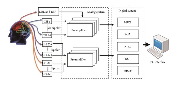
System architecture.
The overall system design adopts Rail-to-Rail characteristics [6], operated under a single-power supply, which consists of analog system design and digital system design. Since each EEG signal has its specific band, so the system designs analog circuit to extract the frequency band from 0.1 to 100 Hz. On the other hand, because of the quite weakness of EEG signals, the magnification of 1000 times is first applied in the analog circuit design to avoid the saturation of amplifier. Then through the digital system design, based on the measured EEG frequency band it conducts digital filtration extracts the matching frequency band, and further magnifies the signals. Considering the problem of signal conversion distortion, according to Nyquist theorem, the sampling rate should be at least 2 times greater than the original rate [7]; on the other hand, the frequency switch of multichannels system will cause crosstalk phenomenon [8], which makes it very important to properly process this part in order to avoid signals distortion and fail to extract signals at the back end.
The signals entering digital system are not easily interfered by noise, and converting the parallel signals into serial signals can reduce the repeated use of the circuit, reducing effectively the circuit size and power consumption. Furthermore, focusing on designing the completion time of signals extraction can avoid signals loss or distortion. The output signals are sent by DSP through UART interface to computer. The following will detail the analog and digital circuit design.
3. Analog System Design
As shown in Figure 2, the input signals of the system consist of three parts, 24 CH single-pole measurement, 8 CH dual-pole measurement, and DRL and REF circuit. In the DRL and REF circuit design, the measurement environment in general is interfered by urban power supply of 110 V/60 Hz, but the design of DRL circuit can avoid the interference and effectively reduce DC bias and protect the tested electrical safety at the same time [9]; in addition, the design of single power supply system must use DRL circuit to provide a VCC/2 reference voltage to the test and improve the overall Vid = Vin1 − Vin2 input signals standard to the design range so that it is accessible to extract both the positive and negative signals. In this system, the DRL circuit is connected to REF circuit to enable the system to single-pole connection and provide common-mode gain more than 120 dB in 60 Hz environment.
Figure 2.
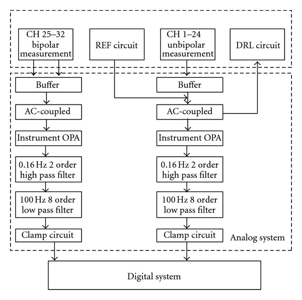
Hardware architecture.
The input end of measuring physiological signals uses the method of electrode pads adhering on the skin which will produce equivalent impedance according to the partial voltage theorem [10]. In the ideal case, OPA characteristic is infinite input impedance, but the skin friction and the electrodes adhesive way will inevitably produce different equivalent impedance which causes the potential at both ends and will fail to provide stable high-input impedance. Therefore, a voltage follower is added before the electrode signals enter to solve the previous problem; on the other hand, with the signals entering, DC bias will be produced which limits the magnification of the op amp, at the same time, high-input impedance will also be mixed with noises. To avoid the previous situations, this system refers to [11, 12] and further designs an improved AC-coupled circuit as shown in Figure 3. Under this circuit structure, the differential input ends of the instrumentation amplifier have the same DC bias level and common mode compensation. So an instrumentation amplifier with high gain can be provided to avoid the output saturation problem caused by DC bias, while the compensated common-mode signals are deducted by the instrumentation amplifier feedback which results in the AC signal errors caused by components errors that can be fixed.
Figure 3.
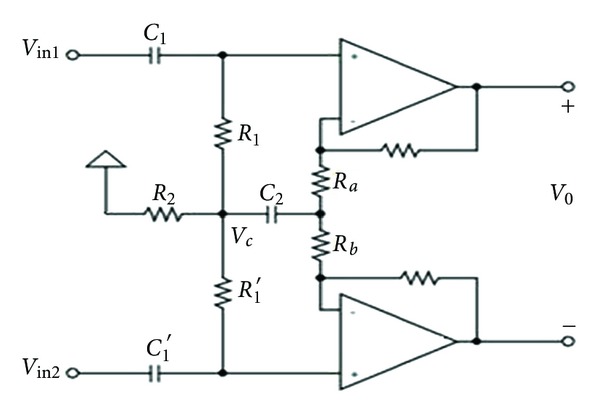
The improved AC-coupled circuit.
For detail analysis of the output voltage of differential-mode and common-mode and CMRR in Figure 3, we assume the following formulas:
| (1) |
If Vid = Vin1 − Vin2 then we can get differential-mode output voltage Vod, and
| (2) |
If Vic = (Vin1 + Vin2)/2, then we can get the common-mode output voltage Voc, and
| (3) |
According to (2) and (4), the differential-mode voltage gain is Aod = Vod/Vid and the common-mode voltage gain is Aoc = Voc/Vic. The CMRR of proposed circuit is
| (4) |
From (4), it can be observed that CMRR is inversely proportional to (τ1 − τ1′). Even if R1 ≠ R1′, and C1 ≠ C1′, we can also get quite high CMRR by choosing the components with little error.
On the other hand, the instrumentation amplifier is used as a major gain, which has the characteristic of high common-mode rejection ratio (CMRR) and can also amplify signals at both ends at the same time, and the output voltage only allows differential voltage pass through, effectively suppressing common mode voltage. To avoid the amplifier fails to operate due to amplifier saturation or too weak, the signals are not amplified at one time. In the analog circuit, the gain is set 1000 times which amplifies the original signals between 1 and 150 mW. In the back-end signals processing, the program amplifier of digital circuit can be reused to process signals.
For the part of signals entering into the filter, because the physiological signals sensing circuit require good noise suppression and time-domain response, based on the design of portability, this system refers to Butterworth to design filter and adopts Sallen-Key architecture that enables to reduce the use of components effectively. Since the system operates in low-frequency band and Sallen-Key is better than MFB in low-frequency response [13], so it is selected for use in this paper. On band width, the system designs a second-order highpass filter of 0.16 Hz and eighth-order lowpass filter of 100 Hz to form a BPF. In the part of second-order highpass filter, this study filters the low-frequency signals of 0.16 Hz in order to meet the IFCN standard and the second-order high-pass design can reduce the error occurrence as well as prefilter the DC bias caused by the front-end circuit, facilitating back-end signals processing [14]; the back-end signals adopt eighth-order low-pass filter of 100 Hz, designed by the support of Nyquist Theorem. If the signal frequency is lower than two times of sampling extraction frequency of converter, although the amplitude might still remain the same, the frequency will change in the process of analog-to-digital conversion which leads to the failure of restoring the original signal. Therefore, the design of filters must also be supported by the analog-to-digital conversion. There is reservation without attenuation in the ideal filter frequency band, whereas the signals of zero on decay curve will decay according to a certain rate. So the filter needs to ensure filtering the frequency of 100 Hz and the sampling extraction frequency at least reaches 200 samples/s, as the actual analog filter is impossible to be close to the ideal design, which requires filtering again in coordination with the sampling rate [15] so as to achieve the best performance. This system designs eighth-order low-pass filter, with roll-off frequency up to 48 dB/octave which makes frequency attenuate about 250 times after frequency of 200 Hz. Taking EEG signals as an example, the original signal is about 50 μV that will decay to 0.2 μV after 200 Hz, which can avoid the original signals within 200 Hz, wherein the frequency band from 100 Hz to 200 Hz can be refiltered by the way of digital filtering, which is also the main purpose of designing eighth-order low-pass filter of 100 Hz.
On the other hand, the front-end filter needs to ensure cutting off the frequency after 100 Hz. Considering the part errors and environment impact as well as the efficiency of its analog-digital conversion and filter design, this system reserves the space which enables to restore better original signals if using sampling frequency of 500 Samples/s; at last, a clamping device is added before the signals into digital system which enhances the signals to positive voltage and extracts the signals by the use of digital system. Other contents such as signal extraction, mixing, and conversion will be discussed in detail in the part of digital system design.
4. Digital System and Man-Machine Interface Design
4.1. Digital System
As shown in Figure 4, the system is a multichannel signal system and the measured signals are continuous signals, which require high signal transmission accuracy. For this case, this system applies analog signal multiplexer, programmable amplifier, analog-digital converter, and digital signal processor to digital system design. In this system, the speed of signals extraction is particularly important. Since the analog signal multiplexer is used to fast switch between multiple channels, so the switching speed must be properly designed and the signals extraction at the back end is required to tone the extraction time, or the continuous signals cannot be extracted. Secondly, because the signals are very weak, at the same time, the actual situation and costs must be taken into account, so IC specification must have the features of single power supply, low crosstalk, and low-voltage detection, which will be described item by item in the following.
Figure 4.
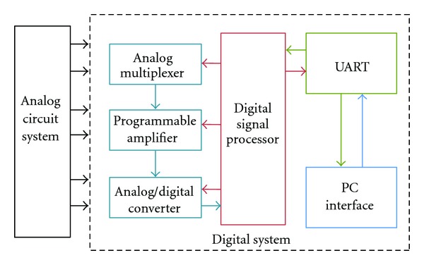
Digital system architecture.
(1) Analog Signal Multiplexer —
The system uses time division multiple (TDM) tasks manner to extract signals by quickly switching channels [16] and convert the parallel signals into serial signals, in which the speed of channel switching is a very important factor because too low signal switching speed will result in signal loss. Therefore, it requires specifying the specification of channel switching speed. In this system, the total number of channels is 32 and the sampling frequency is set as 500 samples/s, so its channel switching speed must be less than 62.5 μs at least and the signals' processing at the back end is also required to reach this standard, or the case of incomplete signal extraction will occur; at the same time, overhigh channel impedance and crosstalk among channels will also affect the signals, which can be solved by the selection of IC specification. Therefore, on the selection of IC, the ADG732 [17] made by ADI is selected, which has 32 CH input and channel switching time up to 30 ns, and its crosstalk is also in accordance with IFCN standards which reaches −72 dB. When the channels work, there will be channel impedance less than 4 Ω which can effectively avoid the signal attenuation. The previous specifications all meet the requirements of this system.
(2) Programmable Amplifier —
EEG amplitude band is from 1 to 160 μV, since the front-end analog circuit provides a gain of 1,000 times, so the signal drops into the range from 1 to 160 mV. The acceptable voltage of the system is from 0 to 5 V, which requires very high accuracy of the programmable amplifier for its calculation. Because over large magnification makes amplifier saturation and too small magnification makes the signals inconspicuous, so the amplifier only needs to provide magnification of 100 times in this phase. For the part of the minimum rate, this amplifier has reached standard without adding analog-digital converter, so the minimum rate of 1 time can be selected. Therefore, this system selects AD8231 [18] made by ADI, which has adjustable gain ratios of 1, 2, 4, 8, 16, 32, 64, 128, amplifying delay time of 200 nS, which all meet the system requirements.
(3) Analog-Digital Converter —
Selection of IC for analog-digital converter is the main consideration, wherein the bits will affect the precision of analog-digital converter [19, 20]. In the standard EEG system, the IFCN requires converter with at least 12-bit resolution which can display at least 0.5 μV change. Since the detection voltage range of this system is from 0 to 5 V, the analog-digital converter with16-bit resolution can be adopted, which has adequate channels completion time, ensuring no losses of signals. As mentioned in the analog system, analog-digital conversion circuit adopts the sampling frequency of 500 samples/s with the main reason being referred in analog system, which ensures filtering the signals with frequency after 200 Hz. At the same time, according to the sampling theorem together with considering parts' error and environments and other factors, the sampling frequency is set as 500 samples/s. It is possible to achieve the voltage of the minimum bit to prove the attenuating signals after 200 Hz will not affect the original signals. When the magnification at the front-end is 1000 times, the smallest display unit can be obtained as 15.2 nV which cannot be extracted by the analog-digital converter because it is too small. But the system requires the signals of 100 Hz and the analog-digital converter will extract the signals within 200 Hz, therefore the extracted signals will be filtered again to achieve the target signals. As for the converter itself, although the gain enables to useless bits, it also amplifies the noise in the process of amplification, in this case, higher bit can get better signals. In this system, signal-to-noise ratio (SNR) is up to 96 dB, proving that the analog-digital converter can provide very high accuracy [21]. Based on the previous considerations, the system adopts AD7663 [22] made by ADI which is a 16-bit converter and can provide conversion rate of 4 μS.
The multichannel system always has insufficient bandwidth phenomenon. Fortunately, the specifications of current components are able to achieve high precision, which help to improve this phenomenon. The following will discuss the conversion rate; as shown in Figure 5, the conversion and completion rate of each component are based on nonideal and shortest completion time in IC specification sheet. It can be found from the figure that a loop of the analog-digital conversion takes longer time, so the analog signal multiplexer and programmable amplifier must coordinate with the rate (4 μS) of the analog-to-digital conversion for operation, or the over delay and loss of signal will occur [23]. Therefore, the analog signal multiplexer and programmable amplifier must be controlled by DSP. After the completion of the analog-to-digital conversion after each operation of conversion and amplification, it can go on the next operation. So under the condition of 32 CHs, calculation within 4 μS, each channel can reach the highest sampling rate of 3.9 k samples/s and achieve the lowest channel completion time (62.5 μS). But this rate is achieved by the nonideal situation of IC specification, while in the overall system, the selected components and PCB layout as well as environment and so on factors must be considered to avoid affecting the actual rate; therefore, the system selects sampling rate of 500 samples/s, which is a more feasible design that can avoid noise and consider the front-end analog circuit and analog-digital conversion.
Figure 5.

Conversion and completion rate.
(4) Digital Signal Processor —
The digital circuit mainly uses DSP-IC-integrated control; in addition to the requirement of adequate I/O control ports in selection for use, the processing speed must also comply with the system. The dsPIC33FJ series [24] is selected for the system, which has 85 digital I/O ports and fast computing capacity of 80 MHz as well as UART output. The overall work flow is shown in Figure 6. First initialize DSP IC containing the system frequency and the UART port and send to DSP end through UART port after the channels and magnification are set by the users at the PC end. The DSP I/O port will configure the analog signal multiplexer, programmable amplifier and analog signal converter after confirming that signals are received. The sampling rate is set by DSP interrupt control, to read parallel I/O port and convert signals into serial signals and then send to PC.
Figure 6.
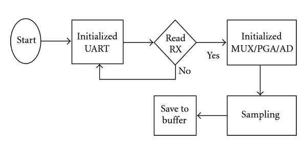
DSP operations.
4.2. Man-Machine Interface
For the part of man-machine interface, the control software at PC end is developed by C++ Builder software which designs a man-machine interface for selection and adjustment and uses UART port to communicate with DSP microprocessor and then processes and displays the received signals by MATLAB software. The software interface is shown in Figure 7(a), which is used to select the channels and amplification for signals verification and modification; Figure 7(b) is used to select the filter band for digital processing, order, as well as scales of x-axis and y-axis for displaying graphics.
Figure 7.
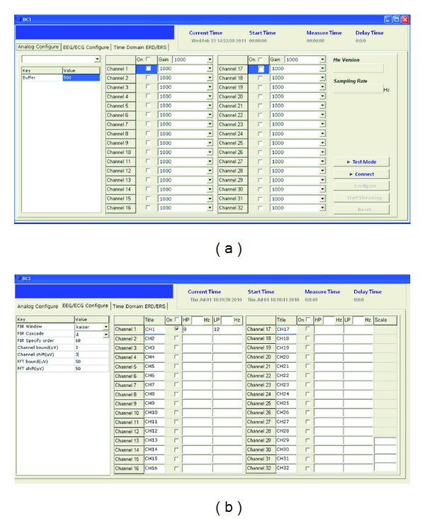
(a) Amplifications and band modifications. (b) Digital filters and display control.
Based on the previous points of view, although analog signals can process nonlinear signals, the more precise signals are processed, the larger hard devices are required, and it cannot be directly controlled flexibly in use. While the digital signal processing is better than analog signal processing both in convenience and in volume, it is unable to extract the small signals and bear the possibility of distortion. In the design of this system, the signals extracted by analog way will be processed and amplified and then more completely processed by digital way, which can achieve better performance.
5. PCB Layout
PCB Layout is a very important part in the fabrication of overall system. Good circuit layout facilitates the actual finished measurement data closer to the simulation data [25], reducing the interference from environment and increasing the stability of overall system. The following will describe the PCB layout rules used in this system.
Before overall circuit layout, stacking manner of PCB board should first be considered. There must be at least a reference plane in the stacked layers of PCB to reduce the EMI generated by different distances between circuit and reference ground. In order to reduce the area of PCB board, the system adopts double-sided SMT layout. The system uses PCB with four layers, which are signal, reference ground, power supply, and signal, respectively, from top to down. Under this stacking way, the signal reference ground plane keeps the same distance and the circuits between layers are insulated because of the reference ground and power supply layer which reduces the EMI caused by their radiation interference [26].
The double-sided hybrid circuit layout of the system adopts the way of double-sided SMT. There are 16 CH circuits on the front and rear side of the PCB board, respectively. We design the three parts of analog, digital, and power on the front side of the circuit, which is shown in Figure 8. Under the conduction structure of EMI, the analog signals are receiver while the digital signals and power signals are interference sources. To block the generation of EMI, it can only add shielding to the transmission path, the longer the distance between these two is, the less the interference is. While in actual case, the distance is limited by the PCB size. Therefore, in the limited PCB board area, they are separated as far as possible in configuration so as to reduce the interference.
Figure 8.
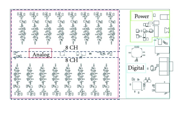
PCB front side configurations.
In the circuit design, the decoupling capacitor for IC is designed to reduce the loop area, but its position on PCB will seriously affect the results. The best way for the decoupling capacitor placing is the position as close as to the power pin of IC and the power supply first will pass through the capacitor before entering IC, as shown in Figure 9. The grounding lead of the capacitor should also be connected with the reference point in order to reduce the circuit area generated additionally by any connection.
Figure 9.
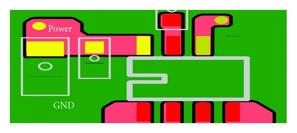
Decoupling capacitor configuration.
The decoupling capacitor of IC is mainly used for protection from conduction interference, while the range of the radiation spreads out from the interference source. In this case, the decoupling capacitor cannot exert their effects. To isolate the radiation interference, the reference ground barrier must be used, which provides a short path with low impedance for radiation interference to avoid the interference on other signals. To achieve this function, Figure 10 shows the system design.
Figure 10.
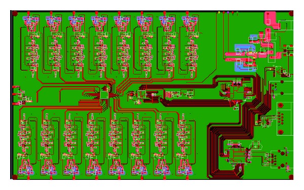
Reference ground barrier of PCB.
6. System Verification
In order to achieve the proper function, the fabrication of this system refers to the IFCN standard for design as shown in Table 1, for example, the sampling frequency, CMRR, the number of channels, and so on; at the same time, in order to verify the functional correctness of the system, it is compared to the traditional EEG, so as to prove that in addition to meeting the IFCN standards, the measurement signals of the system are also verified to be correct.
Table 1.
Proposed system compare with IFCN standards.
| IFCN | This research | |
|---|---|---|
| CMRR (dB) | ≧110 | 130 |
| Rin (Ω) | ≧100 M | 22.5 T |
| HPF (Hz) | ≦0.16 | 0.16 |
| LPF (Hz) | ≧70 | 100 |
| Roll-Off (dB/octave) | ≧12 dB | 48 dB |
| Sample rate | ≧200 | 500 |
| Bits | ≧12 | 16 |
| Voltage | ≦0.5 μV | 15.2 nV |
| |Crosstalk (dB)| | ≧|40| | |72| |
| Channel | ≧24 | 32 |
The measuring point complies with the 10–20 standard electrode position system [27] established by the International Federation of Societies for Electroencephalography and Clinical Neurophysiology, O1 as measuring point, CZ point as reference point and NZ point used for adhering electrodes for DRL. According to related literatures [28], during sleeping and resting with eyes closing, α wave of human body shows significant changes. Therefore, the system adopts α wave to test the situation of eyes opening and closing as well as to measure different EEG signals such as P300 Visual Evoked Potential [29–31], which appears when people concentrates; so this system will focus on comparing and assessing these two cases.
In the process of verification, it mainly focuses on single channel verification due to the measurement of multiple channels which easily confuses in vision because of their narrow distances; at the same time, the environment setting parameters for verification must be the same, such as magnification, measuring points, reference points, and frequencies, as Table 2 shows the front-end parameters set by this system.
Table 2.
Measurement parameters.
| Condition | Parameter | Unit |
|---|---|---|
| Gain | 106 | |
| Sample rate | 500 | Samples/s |
| Wave band | 8–13 | Hz |
| Visual evoked wave band | 2–7 | Hz |
| Test point | 01 | |
| Reference point | CZ | |
| DRL point | NZ |
Since the EEG signals belong to irregular signals, despite measurements on the same points, these two instruments cannot be parallel connected to measure the same points at the same time, so it is impossible to display the same signals. But this problem will not affect the verification of this system. In the process of measurement, it can compare the differences clearly.
First, test the case of eyes opening, as shown in Figure 11, (a) shows the α wave measuring case of traditional EEG machine, while (b) shows the measuring case of this system, which indicates that there is not significant change of EEG signals in both cases.
Figure 11.
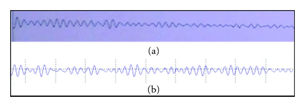
Wave measurement for eye-opening.
Then, as shown in Figure 12, test the case of eyes closing, which shows significant change when compared to that of eyes opening, and the measuring result of this system is similar to that of traditional EEG machine.
Figure 12.
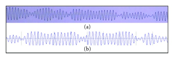
Wave measurement for eye-closing.
Adjusted to the P300 Visual Evoked Potential band, this system designs a simple program in order to trigger Visual Evoked Potential by randomly flashing box in the center of the screen to trigger the test to concentrate on. The test results are shown in Figure 13, in which the red panes are P300 Visual Evoked Potential; obviously, this signal is amplified significantly and is quite different to the other signals. We also use the signal-caught method to control power switches [32].
Figure 13.

P300 visual evoked potential measurement.
Figure 14 is the ECG measured by the system through dual-pole measurement, using one lead measurement way [33]. At the same time, software is applied to set the frequency band and amplification and so forth to support the ECG measurement.
Figure 14.
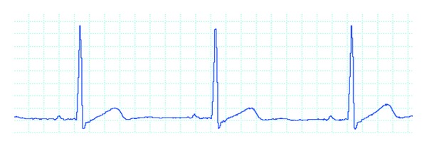
ECG measurements.
Figure 15 is the 32 CH measurement result of this system, in which 16 CHs have EEG signals. While the other 16 CHs are not connected with signals under measurement, This part is not compared to the result of traditional EEG machine with the main reason that multiple channels have narrow distances causing confusion when displayed in zoom, and there is little effect in actual comparison, thus in actual applications, the measurement points of multiple channels should be specified for measuring, by which better verification effect can be achieved.
Figure 15.
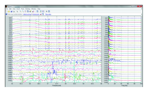
EEG system measurements.
After test, the system is proved to have a certain degree of similarity to the traditional EEG machine, which meets IFCN design standards at the same time. The following discusses the study and experience results.
In the part of measurement, due to the weakness of EEG signal, the external interferences such as sound, light, personal, can overshadow the original EEG signals. Therefore, the measurement verification must be conducted in the same isolation room which can avoid the interferences of noise, urban power supply, and so on. Minimizing the improvable interference factors facilitates to achieve better signal showing in EEG measurement.
Moreover, in common use, if the interference of the urban power supply of 60 Hz is very serious, which can not be completely removed even after DRL processing, the program can be installed to a notebook computer. Moreover, this system design also has USB ports. Using the power supplied by battery of notebook computer, instead of socket outlet, can avoid effectively the interference from urban power supply of 60 Hz, which also becomes a solution. In the part of electrodes adhesion, the system does not design electrode caps for itself. It uses the traditional EEG electrode wires which are fixed by gauze on the brain skin with conductive adhesive coated. The benefit is that it is flexible to be adhered on the particular measurement points. However, for the multichannel measurements, the operations have to be conducted in order which makes it a time-consuming preoperation.
For the part of overall showing, this EEG system is a brain control interface (BCI). Based on the interface designed by C++ Builder, it adopts adjustable magnification and filter frequency band, adjusting the front-end setting through DSP end, and finally sends the result to MATLAB software for processing and displaying. On the other hand, this system has the dual-pole measurement, which can measure different physiological signals. To this system itself, it has the flexibility in use.
7. Conclusions
This study, combining with a variety of OPA uses, builds up the instrumentation amplifier, DRL loop and AC-coupled circuit, and so forth, using high-performance analog signal mixer and programmable amplifier and so on IC to calculate carefully for application, adopting the high-speed processing feature of DSP for control, designing man-machine interface to facilitate the application, which is finally compared to the traditional EEG machine for feasibility verification in an isolated room. At last, a set of multichannel EEG measurement system is developed successfully.
The system has successfully achieved the portable EEG machine 32 CHs with single power supply, whose overall system design is in compliance with IFCN standards, which designs an effective improved AC-coupling circuit with single power supply for the DC bias generated by the friction between the skin and the electrodes, effectively reducing DC bias and improving the error caused by parts errors. At the same time, it proposes an analog circuit design and back-end analog-digital conversion design, as well as how to effectively use the filter and IC to achieve the best performance for the system requirements. At last, a set of EEG man-machine interface is designed, which has adjustable amplification as well as digital filter, and can measure brain waves in different frequencies. Additionally, this system still has 8 CH dual-point measurement which can be used to measure the physiological signals with symmetry like ECG, EMG, and so on, facilitating its more broad applications.
References
- 1.Nuwera MR, Comib G, Emersonc R, et al. IFCN Standards for Digital Recording of Clinical EEG. Elsevier Electroencephalography and Clinical Neurophysiology, vol. 106, no. 3, pp. 259–261, 1998. [DOI] [PubMed]
- 2.Niedermeyer E, da Silva FL. Electroencephalo graphy: Basic Principles, Clinical Applications, and Related Fields. Lippincot Williams & Wilkins; 2004. [Google Scholar]
- 3.Joseph J, Brown JM. Introduction to Biomedical Equipment Technology. 4th edition. Prentice Hall; 1998. [Google Scholar]
- 4.Wolpaw JR, Dennis NB, McFarland DJ, Pfurtscheller G, Vaughan TM. Brain-computer interfaces for communication and control. Clinical Neurophysiology. 2002;113(6):767–791. doi: 10.1016/s1388-2457(02)00057-3. [DOI] [PubMed] [Google Scholar]
- 5.Huhta JC, Webster JG. 60-Hz interference in electro-cardiography. IEEE Transactions on Biomedical Engineering. 1973;20:91–101. doi: 10.1109/TBME.1973.324169. [DOI] [PubMed] [Google Scholar]
- 6.Baker BC. What does ‘Rail to Rail’. Operation Really Mean, Microchip Technology Analog Design Note ADN009, 2004.
- 7.Nyquist H. Certain topics in telegraph transmission theory. Transactions of the AIEE. 1928;47:617–644. [Google Scholar]
- 8. Eliminating alien crosstalk, Communications News, 2009.
- 9.Winter BB, Webter JG. Driven-right-leg circuit design. IEEE Transactions on Biomedical Engineering. 1983;30(1):62–66. doi: 10.1109/tbme.1983.325168. [DOI] [PubMed] [Google Scholar]
- 10.Benning M, Boyd S, Cochrane A, Uddenberg D. The Experimental Portable EEG/EMG Amplifier. University of Victoria Faculty of Engineering ELEC 499A Report. In Partial Fulfillment of the Requirements of the Uvic. B.Eng. Degree Requirements Submitted to Dr Peter Driessen Date, pp. 5-6, 2003.
- 11.Pallas-Areny R. Interference-rejection characteristics of biopotential amplifiers: a comparative analysis. IEEE Transactions on Biomedical Engineering. 1988;35(11):953–959. doi: 10.1109/10.8676. [DOI] [PubMed] [Google Scholar]
- 12.Spinelli EM, Pallàs-Areny R, Mayosky MA. AC-coupled front-end for biopotential measurements. IEEE Transactions on Biomedical Engineering. 2003;50(3):391–395. doi: 10.1109/TBME.2003.808826. [DOI] [PubMed] [Google Scholar]
- 13.Karki J. Active low-pass filter design. Texas Instruments Application Report. 2000
- 14.Baker BC. How do you choose the right amplifier for your low-pass filter. TI Design Report. 2007
- 15.Lin YD, Tsai CD, Huang HH, Chiou DC, Wu CP. Preamplifier with a second-order high-pass filtering characteristic. IEEE Transactions on Biomedical Engineering. 1999;46(5):609–612. doi: 10.1109/10.759062. [DOI] [PubMed] [Google Scholar]
- 16.Wolpaw JR, McFarland DJ. Multichannel EEG-based brain-computer communication. Electroencephalography and Clinical Neurophysiology. 1994;90(6):444–449. doi: 10.1016/0013-4694(94)90135-x. [DOI] [PubMed] [Google Scholar]
- 17.Analog Devices. ADG726/ADG732 Datasheet. 2002.
- 18.Analog Devices. AD8231 Datasheet. 2007.
- 19.Yang HY, Sarpeshkar R. A time-based energy-efficient analog-to-digital converter. IEEE Journal of Solid-State Circuits. 2005;40(8):1590–1601. [Google Scholar]
- 20.McNeill J, Coln MCW, Larivee BJ. ‘Split ADC’ architecture for deterministic digital background calibration of a 16-bit 1-MS/s ADC. IEEE Journal of Solid-State Circuits. 2005;40(12):2437–2444. [Google Scholar]
- 21.Gaddy L. Selecting an A/D Converter. Application Bulletin, 1995.
- 22.Analog Devices. AD7663 Datasheet. 2003.
- 23.Nadeem S, Sodini CG, Lee H-S. 16-channel oversampled analog-to-digital converter. IEEE Journal of Solid-State Circuits. 1994;29(9):1077–1085. [Google Scholar]
- 24.Analog Devices. DsPIC33Fjxxxgpx06/x08/x10 Datasheet. 2007.
- 25.Johns DA, Martin K. Analog Integrated Circuits Design. John Wiley & Sons; 1997. [Google Scholar]
- 26.Oka N, Miyazaki C, Nitta S. Radiation from a PCB with coupling between a low frequency and a digital signal traces. In: Proceedings of the 1998 IEEE International Symposium on Electromagnetic Compatibility; August 1998; pp. 635–640. [Google Scholar]
- 27.Herwig U, Satrapi P, Schönfeldt-Lecuona C. Using the international 10–20 EEG system for positioning of transcranial magnetic stimulation. Brain Topography. 2003;16(2):95–99. doi: 10.1023/b:brat.0000006333.93597.9d. [DOI] [PubMed] [Google Scholar]
- 28.Engin M, Dalbasti T, Güldüren M, Davasli E, Engin EZ. A prototype portable system for EEG measurements. Measurement. 2007;40(9-10):936–942. [Google Scholar]
- 29.Friman O, Volosyak I, Gräser A. Multiple channel detection of steady-state visual evoked potentials for brain-computer interfaces. IEEE Transactions on Biomedical Engineering. 2007;54(4):742–750. doi: 10.1109/TBME.2006.889160. [DOI] [PubMed] [Google Scholar]
- 30.Ahi ST, Kambara H, Koike Y. A dictionary-driven P300 speller with a modified interface. IEEE Transactions on Neural Systems and Rehabilitation Engineering. 2011;19(1):6–14. doi: 10.1109/TNSRE.2010.2049373. [DOI] [PubMed] [Google Scholar]
- 31.Lenhardt A, Kaper M, Ritter HJ. An adaptive P300-based online brain–computer interface. 2010. [DOI] [PubMed]
- 32.Wang CS, Liu CW, Wang TW, et al. Controlling power switch system by P300 visual evoked potential. Applied Mechanics and Materials. 2011;58–60:2493–2498. [Google Scholar]
- 33.Huang HP, Hsu LP. Development of a wearable biomedical health-care system. In: Proceedings of the IEEE IRS/RSJ International Conference on Intelligent Robots and Systems (IROS '05); 2005; pp. 1760–1765. [Google Scholar]


