Abstract
The measurement of angles between anatomical structures is common in radiological and orthopedic practice. Frequently used measurements include scapholunate angle for assessment of wrist instability and Cobb’s angle used for assessment of scoliosis. Measurements of these angles are easily performed on plain X-ray radiographs. However, the situation is more complicated when these measurements are to be performed on cross-sectional (CT or MRI) examinations. On some of the diagnostic workstations, it is not possible to perform angle measurements between the structures if they are not identified on the same image and are located on different images of the same projection or plane. We present a simple solution to measure angles between structures on different images that can be used both in CT and MR.
Keywords: Computed tomography, Image viewer, Magnetic resonance imaging
The measurement of angles between anatomical structures is common in radiological and orthopedic practice. Frequently used measurements include scapholunate angle for assessment of wrist instability [1] and Cobb’s angle used for assessment of scoliosis [2].
Angle measuring tools are available on most of the modern diagnostic workstations.
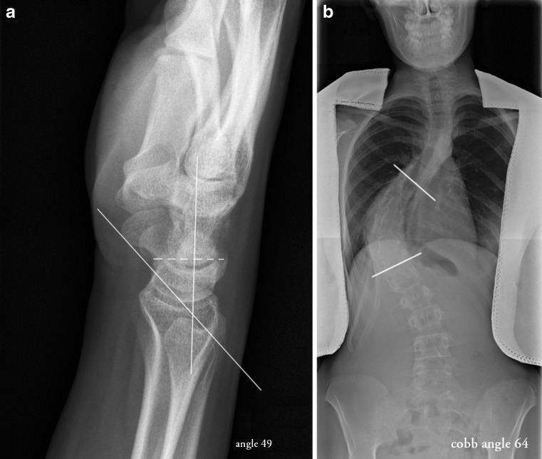
Measurements of these angles are easily performed on plain X-ray radiographs (Fig. 1). However, the situation is more complicated when these measurements are to be performed on cross-sectional (CT or MRI) examinations. The structures involved in angle measurements are often located on different images of the same projection or plane. They are not superimposed and therefore not seen on one image as is the case of plain radiographs. On some of the diagnostic workstations (as, for example, Centricity Radiology RA 1000, GE Healthcare, Barrington, IL, USA or InteleViewer, Intelerad Medical Systems, Montreal, Canada), it is not possible to perform angle measurements between the structures if they are not identified on the same image. We present a simple solution to measure angles between structures in different images obtained or reconstructed in the same plane that can be used both in CT and MR.
Fig. 1.
a Scapholunate angle on plain X-ray radiograph: measured between longitudinal axis of the lunate (drawn perpendicular to a line joining the dorsal and volar poles of the lunate) and a line paralleling the volar cortices of the proximal and distal convexities of the scaphoid. b Cobb’s angle on plain X-ray radiographs: measured between the lines drawn through the superior endplate of the top vertebra (the highest one whose superior surface tilts to the side of the concavity of the curve) and the bottom vertebra (the lowest one whose inferior surface tilts to the side of the concavity of the curve)
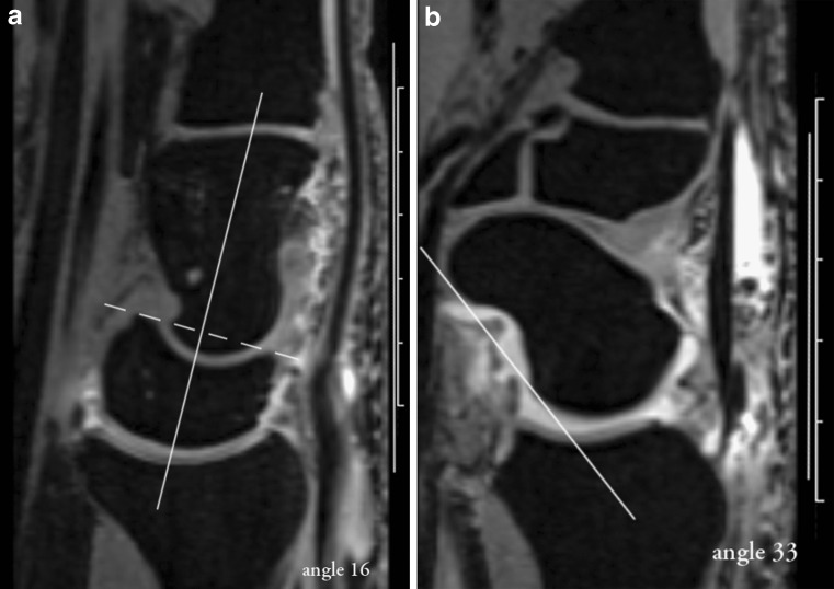
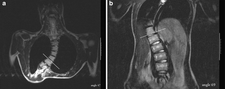
First, a line is placed on a vertical or horizontal measuring scale which is available on most systems. Then a second line is placed through the first of the structures involved in the measuring of the angle. The software calculates and displays the angle measured between the measuring scale and anatomical landmark. The same procedure is done on another image, containing the second anatomical structure/landmark involved in the angle measurement (Figs. 2 and 3).
Fig. 2.
A measuring line is placed on the vertical scale. The second line is placed through the lunate (a) and scaphoid (b) bones on corresponding images. The software calculates and displays the angles measured between the measuring scale and anatomical landmark
Fig. 3.
A measuring line is placed on the vertical scale. The second line is placed through the superior (a) and inferior (b) endplates of the vertebral bodies on corresponding images. The software calculates and displays the angles measured between the measuring scale and anatomical landmark
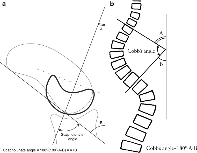
Since the sum of the angles in a triangle is 180°, the Cobb’s angle is calculated by subtraction of the sum of the angles from 180° (Cobb’s angle = 180 − A − B). Scapholunate angle is calculated by summing the angle measurements (scapholunate angle = 180 − (180 − A − B) = A + B; Fig. 4).
Fig. 4.
Graphs, demonstrating calculation of the angles between anatomical structures/landmarks
This method is not intended to substitute the measurements in validated positions for X-ray (upright standing for scoliosis, lateral view of the wrist, obtained with the patient sitting with the elbow at shoulder height and bent 90° for scapholunate angle [3]). In the authors’ opinion, this is a simple method to assess the angles between structures seen on different images in the same projection or plane on cross-sectional examinations which may be used by radiologists while reading the cross-sectional examination. The working preferences are highly individual and there are likely other methods which may be used. We present this technique to help those using diagnostic workstations and PACS system which do not allow measurements of angles between structures on different images on cross sectional exams.
References
- 1.Smith DK, Gilula LA, Amadio PC. Dorsal lunate tilt (DISI configuration): sign of scaphoid fracture displacement. Radiology. 1990;176:497–499. doi: 10.1148/radiology.176.2.2367667. [DOI] [PubMed] [Google Scholar]
- 2.Cobb JR. Outline for the study of scoliosis. In instructional course lectures. Am Acad Orthop Surg (AAOS) 1948;5:261–275. [Google Scholar]
- 3.Zanetti M, Hodler J, Gilula LA. Assessment of dorsal or ventral intercalated segmental instability configurations of the wrist: reliability of sagittal MR images. Radiology. 1998;206:339–345. doi: 10.1148/radiology.206.2.9457184. [DOI] [PubMed] [Google Scholar]


