Abstract
The objective of this study was to develop a patient-specific computational model to quantify the biomechanical interaction between the transcatheter aortic valve (TAV) stent and the stenotic aortic valve during TAV intervention. Finite element models of a patient-specific stenotic aortic valve were reconstructed from multi-slice computed tomography (MSCT) scans, and TAV stent deployment into the aortic root was simulated. Three initial aortic root geometries of this patient were analyzed: (a) aortic root geometry directly reconstructed from MSCT scans, (b) aortic root geometry at the rapid right ventricle pacing phase, and (c) aortic root geometry with surrounding myocardial tissue. The simulation results demonstrated that stress, strain, and contact forces of the aortic root model directly reconstructed from MSCT scans were significantly lower than those of the model at the rapid ventricular pacing phase. Moreover, the presence of surrounding myocardium slightly increased the mechanical responses. Peak stresses and strains were observed around the calcified regions in the leaflets, suggesting the calcified leaflets helped secure the stent in position. In addition, these elevated stresses induced during TAV stent deployment indicated a possibility of tissue tearing and breakdown of calcium deposits, which might lead to an increased risk of stroke. The potential of paravalvular leak and occlusion of coronary ostia can be evaluated from simulated post-deployment aortic root geometries. The developed computational models could be a valuable tool for pre-operative planning of TAV intervention and facilitate next generation TAV device design.
Keywords: Multi-slice computed tomography, Transcatheter aortic valve, Aortic stenosis, Finite element simulation, Patient-specific
Introduction
Aortic stenosis (AS) is the most common valvular disease in developed countries 1 and its prevalence is growing with an aging population2, 3. While surgical aortic valve replacement is still the preferred choice for patients with symptomatic AS, minimally invasive transcatheter aortic valve (TAV) intervention has recently shown promise for elderly high-risk patients who have significant comorbidities 4-6. This revolutionary therapy also has a great potential to treat non high-risk patients, with the advantages of less trauma (without the rigors of open-chest surgery) and shorter recovery time, and thus may fundamentally change the current paradigm of surgical valve replacement.
During TAV intervention, the interventional cardiologist does not have direct access to the calcified aortic valve, and must rely on the interaction between the TAV stent and the host tissue to maintain proper device positioning and function. Many of the adverse effects6-9 seen in clinical trials, such as impairment of coronary flow, cardiac tamponade, stroke, peripheral embolism, aortic injury, paravalvular leak and access site injury 10, 11, can be explained from the biomechanics perspective. For instance, excessive radial expansion force of the TAV stent may cause aortic injury, while insufficient force may lead to paravalvular leakage and device migration. Improper TAV positioning can also cause occlusion of the coronary ostia (CO). Thus, a quantitative understanding of the biomechanics involved in the TAV intervention is critical for the success of this procedure.
Due to the complex geometry, mechanical properties and contact between the TAV stent and the aortic root in TAV intervention, integrated experimental and computational methods are necessary to evaluate the biomechanical response. Finite element (FE) analysis has been utilized to study the biomechanics of the aortic root 12-16 or TAV devices 17-21 individually. However, to the best of our knowledge, the biomechanical interaction between the stenotic aortic valve and TAV stent has been largely unexplored, and therefore is the focus of the present work. Specifically, patient-specific FE models of aortic roots were reconstructed from multi-slice computed tomography (MSCT) scans, and stent expansion during TAV deployment was simulated. Contact force between the stent and aortic root, as well as stress and strain changes in aortic tissue due to the stent expansion were analyzed.
Methods
Patient-Specific Aortic Root Geometry
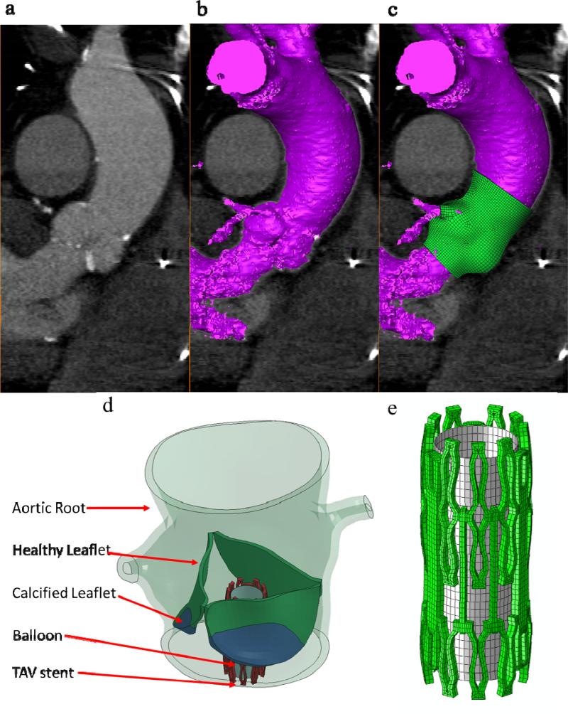
Full phase cardiac MSCT scans were collected from patients at Hartford Hospital (Hartford, CT). Institutional Review Broad approval to review de-identified images was obtained for this study. One stenotic patient with a tricuspid aortic valve and an aortic annulus size of 21 mm was identified from the database. Severe calcification was found in the leaflets of the patient. The MSCT examination was performed on a GE LightSpeed 64-channel volume computed tomography scanner. In general, a total of 2000 slices of images with thickness of 0.625 mm were collected for the whole cardiac cycle22. MSCT images in systole were imported into Avizo 6.3 software (VSG, Burlington, MA) for 3-dimensional (3D) reconstruction and evaluated using a window width of 950 and -50 Hounsfield units. Aortic root and left ventricle were identified and separated from the rest of the chest images to create a 3D representation. A FE mesh of the 3D aortic root model was generated using HyperMesh (Altair Engineering, Inc., MI) software (Figure 1). Three-dimensional solid elements (eight-node hexahedral C3D8I and four-node tetrahedral C3D4 elements) were used to model the aortic root, leaflets, and myocardium.
Figure 1.
(a) MSCT images of the aortic valve in long-axis view overlapped with (b) automatic-segmented interior surface mesh of the aortic valve and (c) the final 3D finite element aortic valve model, (d) TAV stent deployment inside the aortic roots with AS, and (e) TAV stent and balloon.
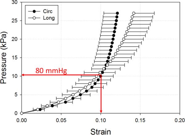
In TAV intervention, a rapid ventricular pacing is introduced during the TAV stent deployment 23, aortic pressure is thus reduced from 80-120 mmHg to 0-20 mmHg. Consequently, the aortic root geometry reconstructed from MSCT scans under normal aortic pressure is different from the aortic root geometry during rapid pacing. Previous studies on patient-specific aortic wall stress showed that neglecting existing stress in CT-reconstructed geometry could lead to inaccurate prediction of wall stress and deformation in FE simulations24, 25. Thus, to estimate the aortic root geometry at the rapid ventricular pacing, we utilized the pressure vs. diameter relationship obtained from in-house inflation tests of human aortic roots; and determined that about 10% strain could be induced by inflating the aortic root from 0 mmHg to 80 mmHg (Figure 2). Therefore, we uniformly applied -10% strain to the CT reconstructed aortic root geometry to approximate the rapid ventricle pacing geometry, which resulted in an aortic root with an annulus size of 19.
Figure 2.
Pressure-strain data (mean and standard error) of human ascending aortas under 200 mmHg (27 kPa) in circumferential (Circ) and longitudinal (Long) directions.
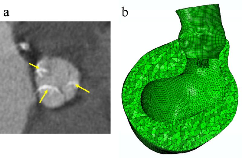
Furthermore, it is known that the aortic root, in particular the aortic annulus, is the main component interacting with the TAV stent for its anchoring. The impact of the myocardium, affixed to the lower parts of the aortic sinuses of Valsalva, on the interactive force during TAV stent deployment is unclear. Thus, in this study, the myocardium surrounding the aortic root was included in the FE models to investigate whether the presence of myocardium would affect the biomechanical interaction between the aortic root and TAV stent (Figure 3b). In summary, we compared three initial geometries for the patient in this study: (a) aortic root geometry (size 21) directly reconstructed from MSCT scans, (b) aortic root geometry (size 19) at the rapid pacing phase, and (c) aortic root geometry (size 19) with surrounding myocardial tissue.
Figure 3.
The presence and severity of aortic leaflet calcifications were evaluated on MSCT images: (a) extensive calcified spots (indicated by yellow arrows) in all leaflets. (b) Finite element models of the aortic roots with myocardium.
Patient Information
The patient with AS was a 77-year-old male. Aortic annulus diameters and CO height were measured from MSCT scans. The aortic valve annulus was defined at the lowest level of the insertion of the valve cusps into the aortic root (Figure 1a). The height of the CO was measured as the axial (vertical) distance from the inferior border of the coronary artery to the aortic annulus plane. For this patient, the maximum and minimum aortic annulus diameters before the TAV stent deployment were 23.6 mm and 17.7 mm respectively. The heights of left and right CO were 10.7 mm and 16.4 mm respectively. In one of our previous studies22, a dimensional analysis of the aortic root geometry of 94 patients was performed using full 3D aortic root geometric models reconstructed from clinical MSCT scans. We found that the aortic root dimensions of the patient used in the current study fell in the typical range of the aortic measurement results obtained in the previous study, thus, this patient is representative in terms of his anatomic dimensions. The area of calcified leaflets quantified from the MSCT images was 127.3 mm2. It was also observed from the MSCT images (Figure 3a) that for this patient, calcified tissue was at the bottom of all three leaflets in the vicinity of the leaflet attachment line.
TAV Stent Geometry and Material
Three-dimensional solid elements (eight-node hexahedral C3D8I) were used to model the TAV stent, while three-dimensional shell elements (four-node reduced quadrilateral S4R elements) were used to model the balloon (Figure 1e). The stent and the balloon were positioned such that the stent was coaxial with the aortic root and approximately one half of the stent was below the aortic annulus based on the manufacturer's guideline for Edwards SAPIEN TAV device deployment 4. The stent was modeled with the properties of cobalt-chromium 26 with a Young's modulus of 243 GPa and a Poisson ratio of 0.3. The stent model had a height of 14.5 mm and a thickness of 0.5 mm. The TAV leaflets were not included in the model because the effects of TAV leaflets on biomechanical interaction between the TAV stent and native tissue during the stent expansion were negligible.
Constitutive Models of Aortic Tissue
An anisotropic hyperelastic material model was adopted to characterize mechanical behaviors of the aortic tissues (i.e., aortic leaflets, aortic sinus, ascending aorta and surrounding myocardium). The model is based on the fiber-reinforced hyperelastic material model proposed by Holzapfel et al. 27, 28, which has been shown to accurately capture the behavior of blood vessel inflation under internal pressurization. Briefly, the aortic tissues are assumed to be composed of a matrix material with two families of imbedded fibers, each of which has a preferred direction. The fiber directions (theta) can be mathematically described using two unit vectors. The strain invariant is used to describe the matrix material; and the strain invariant is used to describe the properties of the fiber families. is equal to the squares of the stretches in the fiber directions. The strain energy function W can be expressed as
| (1) |
where, C10, C01, k1, k2 and D are material constants. C10 and C01 are used to describe the matrix material. D is the material constant that introduces the near incompressibility, while k1 is a positive material constant with the dimensions of stress and k2 is a dimensionless parameter. In addition, a dispersion parameter κ was used to describe the distribution of fiber orientation. When κ=0, the fibers are perfectly aligned (no dispersion). When κ=0.33, the fibers are randomly distributed and the material becomes isotropic. The anisotropic hyperelastic material model was implemented into Abaqus 6.10 (SIMULIA, Providence, RI) with a user sub-routine VUMAT. Local coordinate systems were defined for each leaflet, sinus, and myocardium to include fiber orientations for each region.
Material Parameters Obtained from Inverse FE Method
Load-controlled biaxial tests of healthy human aortic valve leaflets, aortic sinuses and ascending aorta (80-year-old female) were reported by Martin et al. 29. In addition, an in-house load-controlled biaxial test of healthy human myocardium (79-year-old female) was used. Briefly, a square specimen (about 25 mm in length) of the posterior side below the coronary sinus of the left ventricle wall was cut out and sliced into three layers: endothelium, myocardium and epicardium. The thickness of the endothelium, myocardium, and epicardium are 1.99, 2.47 and 2.17 mm, respectively. In this study, the myocardium mechanical properties were generalized by obtaining only the myocardium layer to present the entire left ventricle wall. To determine the passive characteristics of the myocardium, the specimen was submerged and tested in a Ca2+-free saline solution with EGTA (a chelating agent with a high affinity for Ca2+) and 0.1M papaverine. Biaxial testing was carried out according to the methods presented in Sacks and Sun 30. The longitudinal and circumferential axes were aligned with the apex to base and circumferential directions of the heart, respectively. The specimen was preconditioned for 20 cycles with a maximum load of 80g in each direction.
An inverse FE method was used to estimate the model parameters by comparing FE simulated tissue responses with the experimental data. Briefly, in this procedure, an equal-biaxial loading protocol was applied to a single solid element to simulate the responses of aortic tissue. The material parameters of the constitutive model of Eqn. (1) were obtained by iteratively minimizing the difference between stress-strain relationships extracted from the single element simulation and the experimental data. This process is automatically realized by using a Matlab code that executes the simulation, extracts data from simulation output files and performs optimization of the parameters.
Modeling of Calcified Leaflets
Leaflet calcification of the patient in this study had distinct and regional calcified tissue formations (Figure 3) that can be observed from the MSCT images. The focal calcified regions of the leaflets were modeled in the FE models according to their size, thickness, and location based on the MSCT images. Calcified tissues were modeled with the properties of hydroxyapatite with a Young's modulus of 60 GPA and a Poisson ratio of 0.3.
Boundary Conditions
A displacement-controlled deformation was prescribed to the balloon in its radial direction so that it expanded the TAV stent to an outer diameter of 23 mm. The displacement-controlled condition was utilized based on the clinical observation that most of the Edwards SAPIEN stents used remained circular in cross-section after deployment, even within heavily calcified native valves31. The top of the ascending aorta was constrained to allow only rotational degrees of freedom. Friction coefficients between TAV stents and stenotic aortic roots are currently unknown. Thus, in this study, frictional coefficient of 0.1 was assumed based on the study by Vad et al. 32 on a self-expanding endovascular stent-graft. To evaluate the effect of the mesh density on simulation results, a mesh sensitivity study was performed on the FE models.
Results
Material Models
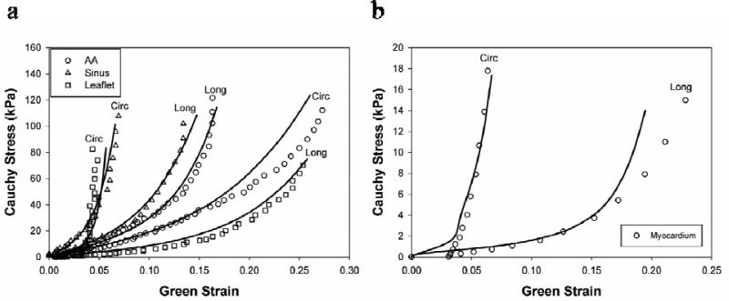
The best-fitted material properties of aortic tissue as well as the corresponding biaxial test data are illustrated in Figure 4. The obtained material parameters are listed in Table 1. It can be seen in Figure 4 that there was very good correlation between simulation and biaxial results. From the biaxial results it can be seen that the sinus and aortic leaflet tissues had stiffer mechanical response in the circumferential direction, while the ascending aorta was stiffer in the longitudinal direction. This intrinsic material property was reflected in the material model by the angle (theta) between collagen fibers and the circumferential direction, which was larger for the ascending aorta in Table 1.
Figure 4.
Equal-biaxial results (circles) of the (a) aortic sinus, ascending aorta, leaflet, (b) myocardium in circumferential (Circ) and longitudinal (Long) directions and their responses predicted by finite element simulations (lines).
Table 1.
Material parameters of healthy human aortic sinus, ascending aorta, leaflet, and myocardium
| C10 | C01 | K1 | K2 | κ | D | Theta (°) | |
|---|---|---|---|---|---|---|---|
| Sinus | 1.7553 | 13.7077 | 10.5507 | 80.3790 | 0.0006 | 0.0005 | 20.06 |
| Ascending aorta | 4.1755 | 3.4649 | 3.7711 | 15.9276 | 0.0864 | 0.0005 | 70.95 |
| Leaflet | 0.9627 | 6.3928 | 12.7250 | 48.6769 | 0.0711 | 0.0005 | 28.04 |
| Myocardium | 0.0374 | 15.3875 | 6.0798 | 98.3666 | 0.1440 | 0.0005 | 6.78 |
Simulation Results
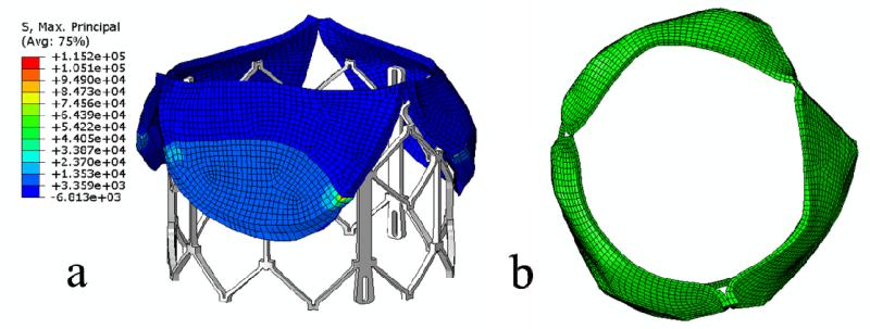
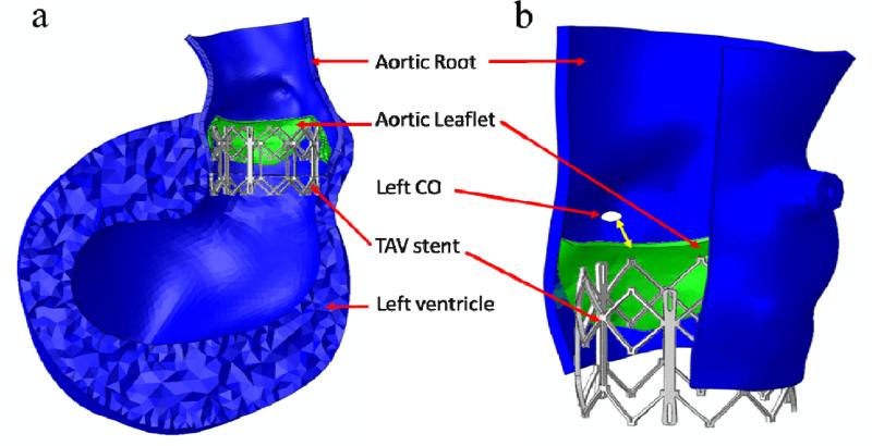
The deformed leaflets and aortic root of the patient after the maximum stent deployment are shown in Figure 5 and Figure 6. Aortic leaflets were pushed behind the TAV stent. No severe leaflet overhanging or obstruction of CO was observed. The distance between the left CO and the leaflet free edge was found to be 3.6 mm (as indicated by the double-sided yellow arrow in Figure 6b). The maximum and minimum aortic annulus diameters after the TAV stent deployment were 24.6 mm and 23.1 mm respectively. Also, no significant change in CO heights was observed before and after TAV stent deployment.
Figure 5.
Side views (a) and top views (b) of deformed native valve leaflets of the patient after the maximum stent deployment.
Figure 6.
(a) Side view of deformed aortic root and left ventricle of the patient after the maximum stent deployment. (b) Double-sided yellow arrow shows the distance between the left CO and deformed leaflet free edge.
Contact forces between the stent and aortic root are listed in Table 2. Contact forces of the aortic root models reconstructed directly from MSCT scans (size 21) were significantly lower than those of the scaled aortic root models (size 19). Furthermore, contact forces increased slightly with the inclusion of myocardium to the model. Similarly, as listed in Table 2, maximum stresses and strains of the original aortic root models were lower than those of the scaled models. The presence of myocardium induced slightly higher stresses and strains in the aortic root.
Table 2.
Mechanical responses of the aortic root at maximum TAV stent expansion
| Mechanical Responses | Geometry | ||
|---|---|---|---|
| #1 | #2 | #3 | |
| Contact normal force (N) | 27.64 | 125.70 | 149.02 |
| Contact shear force (N) | 2.68 | 11.09 | 12.58 |
| Peak MPS in the calcium deposit regions of leaflets (MPa) | 115.2 | 564.1 | 641.2 |
| Peak MPS in leaflet tissue within 1 mm vicinity of the calcium deposits (MPa) | 5.37 | 36.49 | 44.41 |
| Peak MPS in leaflet tissue beyond 1 mm vicinity of the calcium deposits | 3.51 | 13.03 | 13.03 |
| Average MPS in leaflet tissue, excluding the calcium deposit regions (MPa) | 0.50 | 2.67 | 2.91 |
| Average MPS in aortic sinus tissue* (MPa) | 0.17 | 0.86 | 0.87 |
Footnote: #1 is the initial aortic root geometry (size 21) which is reconstructed directly from MSCT images, #2 is the scaled aortic root geometry (size 19) which represents the rapid pacing geometry, and #3 is the scaled aortic root geometry (size 19) with the addition of surrounding myocardium.
averaged over the aortic sinus elements below the commissures. MPS is the Maximum Principal Stress in the unit of MPa.
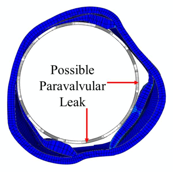
The stress distribution in the aortic leaflets, as well as the deformed leaflets and stent geometries, are shown in Figure 5 and Table 2. Generally, highest stresses were observed at the calcified spots of the leaflets as well as the transition region between calcified and native tissues (Table 2). High stress and strain was also observed at the leaflet-root attachment lines and at the aortic wall between leaflets where the aortic root contacted the stent struts. The top views of the deformed aortic root cross-sections at maximum stent deployment are shown in Figure 7. Due to the calcified leaflets, the deformed shape of the aortic annulus of the patient was not circular and thus, gaps can be seen between the stent and annulus, which indicated a potential of paravalvular leak.
Figure 7.
Sectional view of the deformed aortic roots of the patient at the maximum stent deployment showed the possible paravalvular leak locations.
Mesh Sensitivity Analysis
The element number of the aortic root and leaflets was increased from 5408 to 21632 to 86520. Mesh sensitivity was also conducted varying the number of elements of the stents from 735 to 5880. There was approximately 0.8 % difference in peak contact normal force between the original and finest mesh. The differences in average maximum principal stress and strain in the aortic root between the original and finest mesh were roughly 5.1% and 3.8% respectively.
Discussion
Successful TAV deployment and function are heavily reliant on the aortic root-TAV stent interaction. Since the human aortic valve has a large variation of anatomic structures, e.g. different annulus size, sinus height, CO location 22, 33, 34 and tissue stiffness 29, determination of appropriate interaction forces between the TAV and the native tissue using either in vivo or ex vivo measurements is a challenging task. In this study we conducted a FE analysis of one patient in TAV intervention and quantified the associated interactive forces, stresses and strains in this procedure.
Stress analysis of patient-specific vascular structures commonly assume that the reconstructed in vivo geometries derived from biomedical images are stress–free, although they are in a pre-deformed state due to the presence of arterial pressure 35. In this study, the simulation results clearly demonstrated that there was a significant difference in stress, strain, and contact forces between the aortic root models directly reconstructed from MSCT scans (size 21) and the scaled aortic root models (size 19) for the rapid ventricular pacing phase, which underscores the importance of choosing an appropriate initial aortic root geometry in FE simulation. It is noted that our scaled aortic root geometry is a rough approximation and will not be accurate at a patient-specific level. Ideally, 3D imaging modalities such as CT scans may be performed at the rapid pacing phase such that an accurate estimation of the aortic root geometry at 0-20 mmHg can be obtained. Alternatively, an inverse FE method could be used to deduce the aortic root geometry at the rapid pacing using the approach by Zhou et al. 35. In addition, in the FE models we did not consider the aortic wall residual stress 36. For AS patients the aortic root is heavily calcified. The impact of such calcification on the arterial wall residual stress is currently unknown. However, the residual stress, if included in the FE model, should make the aortic root more compliant.
The simulation results also indicated that the surrounding myocardium contributed to the increase of the mechanical responses during TAV deployment. We noted that the passive myocardium tissue in the aged patients was much more compliant compared to the aortic root tissues. Thus, its contribution to the biomechanical interaction might be secondary. However, in our simulations the active contraction from myocardium was not considered, which, if considered, should increase the interactive forces imposed on the TAV stent during the cardiac cycle.
Calcified leaflets are removed during a surgical valve replacement procedure. In current TAV interventions, however, the leaflets are not removed, but rather pushed aside by the TAV stent. Whether these leaflets have any mechanical impact on the TAV intervention is currently unclear. It has been suggested that these calcified leaflets be removed prior to the TAV intervention by a separate minimally invasive means 37. Our simulation results showed that high stress concentrations (Table 2) were seen around the calcified regions in the leaflets as well as at the attachment lines of leaflets and the aortic sinuses. These high stress concentrations indicated that the leaflets carried a substantial amount of loads, thus, helped secure the stent in position 38. However, the high stress concentrations around the calcified regions also suggested a potential of tissue tearing and breakdown of calcium deposits in these regions, which might cause an increased risk of stroke 4.
Limitations
No rupture or damage mechanism has been incorporated into our FE model. The peak stresses observed in the calcified tissue are high enough to cause tissue tearing and breakdown of calcifications. Fracture of the calcification could reduce the overall stiffness of the aortic root and leaflets, thus, the radial force that the TAV stent exerted on the aortic root could decrease. The angle of collagen fiber orientation was assumed to be a constant; and was determined from optimization of material parameters against biaxial test data. Future work will be needed to obtain the collagen fiber orientation from histology analysis of aortic and left ventricle tissues. No study was found in the literature 39-41 on the material stiffness of aortic leaflet calcification. Therefore, we used the properties of hydroxyapatite to model the calcification rocks. Additional experimental data is required to verify our assumption and the values we used in our simulations.
Conclusions
Patient-specific FE models of stenotic aortic roots were reconstructed from MSCT scans; and TAV stent deployment was simulated. The results showed that mechanical responses of the aortic root model directly reconstructed from MSCT scans were significantly lower than those of the model at the rapid ventricular pacing phase. In addition, inclusion of the myocardium slightly increased the mechanical responses. It was observed that maximum stresses and strains were in the region of leaflet calcification, which could help secure the stent in position. Moreover, these elevated stresses during TAV stent deployment indicated a possibility of tissue tearing and breakdown of calcium deposits, which might lead to an increased risk of stroke. The potential of paravalvular leak or occlusion of coronary ostia can be evaluated from simulated post-deployment aortic root geometries. The developed computational models could be a valuable tool for pre-operative planning of TAV intervention and facilitate next generation TAV device designs.
Acknowledgements
This work was supported in part by the State of Connecticut Department of Public Health Biomedical Research Grant DPH2010-0085, a NSF GRFP fellowship, NIH 1R01HL104080 and 1R21HL108239 grants. We would like to thank Dr. Charles Primiano and Dr. Raymond McKay for providing CT scans. We would also like to thank Thuy Pham and Caitlin Martin for providing experimental data of the aortic tissues.
Footnotes
Publisher's Disclaimer: This is a PDF file of an unedited manuscript that has been accepted for publication. As a service to our customers we are providing this early version of the manuscript. The manuscript will undergo copyediting, typesetting, and review of the resulting proof before it is published in its final citable form. Please note that during the production process errors may be discovered which could affect the content, and all legal disclaimers that apply to the journal pertain.
Conflict of Interest Statement
All authors disclose any financial and personal relationships with other people or organizations that could inappropriately influence (bias) their work.
References
- 1.Carabello BA, Paulus WJ. Aortic stenosis. Lancet. 2009;373(9667):956–966. doi: 10.1016/S0140-6736(09)60211-7. [DOI] [PubMed] [Google Scholar]
- 2.Merryman WD. Mechano-potential etiologies of aortic valve disease. Journal of Biomechanics. 2010;43(1):87–92. doi: 10.1016/j.jbiomech.2009.09.013. [DOI] [PMC free article] [PubMed] [Google Scholar]
- 3.Stewart BF, Siscovick D, Lind BK, Gardin JM, Gottdiener JS, Smith VE, Kitzman DW, Otto CM. Clinical factors associated with calcific aortic valve disease. Cardiovascular Health Study. Journal of the American College of Cardiology. 1997;29(3):630–634. doi: 10.1016/s0735-1097(96)00563-3. [DOI] [PubMed] [Google Scholar]
- 4.Leon MB, Smith CR, Mack M, Miller DC, Moses JW, Svensson LG, Tuzcu EM, Webb JG, Fontana GP, Makkar RR, Brown DL, Block PC, Guyton RA, Pichard AD, Bavaria JE, Herrmann HC, Douglas PS, Petersen JL, Akin JJ, Anderson WN, Wang D, Pocock S, Investigators PT. Transcatheter aortic-valve implantation for aortic stenosis in patients who cannot undergo surgery. New England Journal of Medicine. 2010;363(17):1597–1607. doi: 10.1056/NEJMoa1008232. [DOI] [PubMed] [Google Scholar]
- 5.Webb J, Cribier A. Percutaneous transarterial aortic valve implantation: what do we know? Eur Heart J. 2010;32(2):140–147. doi: 10.1093/eurheartj/ehq453. [DOI] [PubMed] [Google Scholar]
- 6.Ye J, Cheung A, Lichtenstein SV, Nietlispach F, Albugami S, Masson JB, Thompson CR, Munt B, Moss R, Carere RG, Jamieson WR, Webb JG. Transapical transcatheter aortic valve implantation: follow-up to 3 years. J Thorac Cardiovasc Surg. 2010;139(5):1107–1113. e1101. doi: 10.1016/j.jtcvs.2009.10.056. 1113. [DOI] [PubMed] [Google Scholar]
- 7.Gurvitch R, Wood DA, Tay EL, Leipsic J, Ye J, Lichtenstein SV, Thompson CR, Carere RG, Wijesinghe N, Nietlispach F, Boone RH, Lauck S, Cheung A, Webb JG. Transcatheter Aortic Valve Implantation: Durability of Clinical and Hemodynamic Outcomes Beyond 3 Years in a Large Patient Cohort. Circulation. 2010;122(13):1319–1327. doi: 10.1161/CIRCULATIONAHA.110.948877. [DOI] [PubMed] [Google Scholar]
- 8.Webb JG, Altwegg L, Boone RH, Cheung A, Ye J, Lichtenstein S, Lee M, Masson JB, Thompson C, Moss R, Carere R, Munt B, Nietlispach F, Humphries K. Transcatheter aortic valve implantation: impact on clinical and valve-related outcomes. Circulation. 2009;119(23):3009–3016. doi: 10.1161/CIRCULATIONAHA.108.837807. [DOI] [PubMed] [Google Scholar]
- 9.Zajarias A, Cribier AG. Outcomes and safety of percutaneous aortic valve replacement. J Am Coll Cardiol. 2009;53(20):1829–1836. doi: 10.1016/j.jacc.2008.11.059. [DOI] [PubMed] [Google Scholar]
- 10.Grube E, Schuler G, Buellesfeld L, Gerckens U, Linke A, Wenaweser P, Sauren B, Mohr F, Walther T, Zickmann B, Iversen S, Felderhoff T, Cartier R, Bonan R. Percutaneous aortic valve replacement for severe aortic stenosis in high-risk patients using the second- and current third-generation self-expanding CoreValve prosthesis: device success and 30-day clinical outcome. J Am Coll Cardiol. 2007;50(1):69–76. doi: 10.1016/j.jacc.2007.04.047. [DOI] [PubMed] [Google Scholar]
- 11.Webb J, Pasupati S, Humphries K, Thompson C, Altwegg L, Moss R, Sinhal A, Carere R, Munt B, Ricci D, Ye J, Cheung A, Lichtenstein S. Percutaneous transarterial aortic valve replacement in selected high-risk patients with aortic stenosis. Circulation. 2007;116(7):755–763. doi: 10.1161/CIRCULATIONAHA.107.698258. [DOI] [PubMed] [Google Scholar]
- 12.Auricchio F, Conti M, Morganti S, Totaro P. A computational tool to support pre-operative planning of stentless aortic valve implant. Med Eng Phys. 2011 doi: 10.1016/j.medengphy.2011.05.006. [DOI] [PubMed] [Google Scholar]
- 13.Conti CA, Votta E, Della Corte A, Del Viscovo L, Bancone C, Cotrufo M, Redaelli A. Dynamic finite element analysis of the aortic root from MRI-derived parameters. Med Eng Phys. 2010;32(2):212–221. doi: 10.1016/j.medengphy.2009.12.003. [DOI] [PubMed] [Google Scholar]
- 14.Dwyer HA, Matthews PB, Azadani A, Ge L, Guy TS, Tseng EE. Migration forces of transcatheter aortic valves in patients with noncalcific aortic insufficiency. Journal of Thoracic & Cardiovascular Surgery. 2009;138(5):1227–1233. doi: 10.1016/j.jtcvs.2009.02.057. [DOI] [PubMed] [Google Scholar]
- 15.Labrosse MR, Lobo K, Beller CJ. Structural analysis of the natural aortic valve in dynamics: from unpressurized to physiologically loaded. J Biomech. 2010;43(10):1916–1922. doi: 10.1016/j.jbiomech.2010.03.020. [DOI] [PubMed] [Google Scholar]
- 16.Mangini A, Lemma MG, Soncini M, Votta E, Contino M, Vismara R, Redaelli A, Antona C. The aortic interleaflet triangles annuloplasty: a multidisciplinary appraisal. Eur J Cardiothorac Surg. 2011 doi: 10.1016/j.ejcts.2010.12.038. [DOI] [PubMed] [Google Scholar]
- 17.Haj-Ali R, Dasi LP, Kim HS, Choi J, Leo HW, Yoganathan AP. Structural simulations of prosthetic tri-leaflet aortic heart valves. Journal of Biomechanics. 2008;41(7):1510–1519. doi: 10.1016/j.jbiomech.2008.02.026. [DOI] [PubMed] [Google Scholar]
- 18.Kumar GV, Mathew L. Effects of design parameters on the radial force of percutaneous aortic valve stents. Cardiovasc Revasc Med. 2010;11(2):101–104. doi: 10.1016/j.carrev.2009.04.005. [DOI] [PubMed] [Google Scholar]
- 19.Li K, Sun W. Simulated thin pericardial bioprosthetic valve leaflet deformation under static pressure-only loading conditions: implications for percutaneous valves. Ann Biomed Eng. 2010;38(8):2690–2701. doi: 10.1007/s10439-010-0009-3. [DOI] [PubMed] [Google Scholar]
- 20.Smuts AN, Blaine DC, Scheffer C, Weich H, Doubell AF, Dellimore KH. Application of finite element analysis to the design of tissue leaflets for a percutaneous aortic valve. J Mech Behav Biomed Mater. 2010;4(1):85–98. doi: 10.1016/j.jmbbm.2010.09.009. [DOI] [PubMed] [Google Scholar]
- 21.Sun W, Li K, Sirois E. Simulated elliptical bioprosthetic valve deformation: implications for asymmetric transcatheter valve deployment. Journal of Biomechanics. 2010;43(16):3085–3090. doi: 10.1016/j.jbiomech.2010.08.010. [DOI] [PubMed] [Google Scholar]
- 22.Wang Q, Book G, Contreras Ortiz S, Primiano C, McKay R, Kodali S, Sun W. Dimensional Analysis of Aortic Root Geometry During Diastole Using 3D Models Reconstructed from Clinical 64-Slice Computed Tomography Images. Cardiovascular Engineering and Technology. 2011:1–10. [Google Scholar]
- 23.Webb JG, Pasupati S, Achtem L, Thompson CR. Rapid pacing to facilitate transcatheter prosthetic heart valve implantation. Catheterization & Cardiovascular Interventions. 2006;68(2):199–204. doi: 10.1002/ccd.20829. [DOI] [PubMed] [Google Scholar]
- 24.Lu J, Zhou X, Raghavan ML. Inverse method of stress analysis for cerebral aneurysms. Biomechanics & Modeling in Mechanobiology. 2008;7(6):477–486. doi: 10.1007/s10237-007-0110-1. [DOI] [PubMed] [Google Scholar]
- 25.Speelman L, Bosboom EM, Schurink GW, Buth J, Breeuwer M, Jacobs MJ, van de Vosse FN. Initial stress and nonlinear material behavior in patient-specific AAA wall stress analysis. Journal of Biomechanics. 2009;42(11):1713–1719. doi: 10.1016/j.jbiomech.2009.04.020. [DOI] [PubMed] [Google Scholar]
- 26.Marrey RV, Burgermeister R, Grishaber RB, Ritchie RO. Fatigue and life prediction for cobalt-chromium stents: A fracture mechanics analysis. Biomaterials. 2006;27(9):1988–2000. doi: 10.1016/j.biomaterials.2005.10.012. [DOI] [PubMed] [Google Scholar]
- 27.Holzapfel GA, Gasser TC, Ogden RW. A new constitutive framework for arterial wall mechanics and a comparative study of material models. J. Elasticity. 2000;61:1–48. [Google Scholar]
- 28.Gasser TC, Ogden RW, Holzapfel GA. Hyperelastic modelling of arterial layers with distributed collagen fibre orientations. Journal of the Royal Society Interface. 2006;3(6):15–35. doi: 10.1098/rsif.2005.0073. [DOI] [PMC free article] [PubMed] [Google Scholar]
- 29.Martin C, Pham T, Sun W. Significant differences in the material properties between aged human and porcine aortic tissues. European Journal of Cardio-Thoracic Surgery. 2011;40(1):28–34. doi: 10.1016/j.ejcts.2010.08.056. [DOI] [PMC free article] [PubMed] [Google Scholar]
- 30.Sacks MS, Sun W. Multiaxial mechanical behavior of biological materials. Annu Rev Biomed Eng. 2003;5:251–284. doi: 10.1146/annurev.bioeng.5.011303.120714. [DOI] [PubMed] [Google Scholar]
- 31.Sanchez-Giron C, De Icaza Herrera M, Eltchaninoff H, Godin M, Tron C, Baala B, Cribier A. Circularity Index in deployed Edwards Sapien aortic valve bioprosthesis. European Heart Journal. 2009;30:920. doi: 10.4244/eijv5i4a69. Abstract Supplement. [DOI] [PubMed] [Google Scholar]
- 32.Vad S, Eskinazi A, Corbett T, McGloughlin T, Vande Geest JP. Determination of coefficient of friction for self-expanding stent-grafts. Journal of Biomechanical Engineering. 2010;132(12):121007. doi: 10.1115/1.4002798. [DOI] [PubMed] [Google Scholar]
- 33.Stolzmann P, Knight J, Desbiolles L, Maier W, Scheffel H, Plass A, Kurtcuoglu V, Leschka S, Poulikakos D, Marincek B, Alkadhi H. Remodelling of the aortic root in severe tricuspid aortic stenosis: implications for transcatheter aortic valve implantation. European Radiology. 2009;19(6):1316–1323. doi: 10.1007/s00330-009-1302-0. [DOI] [PubMed] [Google Scholar]
- 34.Tops LF, Wood DA, Delgado V, Schuijf JD, Mayo JR, Pasupati S, Lamers FP, van der Wall EE, Schalij MJ, Webb JG, Bax JJ. Noninvasive evaluation of the aortic root with multislice computed tomography implications for transcatheter aortic valve replacement. JACC Cardiovasc Imaging. 2008;1(3):321–330. doi: 10.1016/j.jcmg.2007.12.006. [DOI] [PubMed] [Google Scholar]
- 35.Zhou X, Raghavan ML, Harbaugh RE, Lu J. Patient-specific wall stress analysis in cerebral aneurysms using inverse shell model. Annals of Biomedical Engineering. 2010;38(2):478–489. doi: 10.1007/s10439-009-9839-2. [DOI] [PMC free article] [PubMed] [Google Scholar]
- 36.Fung YC, Liu SQ, Zhou JB. Remodeling of the constitutive equation while a blood vessel remodels itself under stress. J Biomech Eng. 1993;115(4B):453–459. doi: 10.1115/1.2895523. [DOI] [PubMed] [Google Scholar]
- 37.Hauck F, Wendt D, Muller W, Stuhle S, Wendt H, Thielmann M, Kipfmuller B, Vogel B, Jakob H. A new tool for the resection of aortic valves: In-vitro results for turning moments and forces using Nitinol cutting edges. Minim Invasive Ther Allied Technol. 2009;18(3):164–171. doi: 10.1080/13645700902921575. [DOI] [PubMed] [Google Scholar]
- 38.Zegdi R, Ciobotaru V, Noghin M, Sleilaty G, Lafont A, Latremouille C, Deloche A, Fabiani JN. Is it reasonable to treat all calcified stenotic aortic valves with a valved stent? Results from a human anatomic study in adults. Journal of the American College of Cardiology. 2008;51(5):579–584. doi: 10.1016/j.jacc.2007.10.023. [DOI] [PubMed] [Google Scholar]
- 39.Ebenstein DM, Coughlin D, Chapman J, Li C, Pruitt LA. Nanomechanical properties of calcification, fibrous tissue, and hematoma from atherosclerotic plaques. Journal of Biomedical Materials Research. Part A. 2009;91(4):1028–1037. doi: 10.1002/jbm.a.32321. [DOI] [PubMed] [Google Scholar]
- 40.Holzapfel GA, Sommer G, Regitnig P. Anisotropic mechanical properties of tissue components in human atherosclerotic plaques. Journal of Biomechanical Engineering. 2004;126(5):657–665. doi: 10.1115/1.1800557. [DOI] [PubMed] [Google Scholar]
- 41.Jeziorska M, McCollum C, Wooley DE. Observations on bone formation and remodelling in advanced atherosclerotic lesions of human carotid arteries. Virchows Archiv. 1998;433(6):559–565. doi: 10.1007/s004280050289. [DOI] [PubMed] [Google Scholar]


