Abstract
We have proposed four dimensional (4D) digitally reconstructed radiography (DRR) for verifying a lung tumor position during volumetric modulated arc therapy (VMAT). An internal target volume (ITV) was defined based on two clinical target volumes (CTVs) delineated on maximum exhalation and maximum inhalation images acquired by 4D planning computed tomography (CT). A planning target volume (PTV) was defined by adding a margin of 5 mm to the ITV on the maximum exhalation 3D CT images. A single-arc VMAT plan was created on the same CT data using Pinnacle SmartArc with a maximum multi-leaf collimator leaf speed of 1 mm/degree, thereby resulting in quasi-conformal field shapes while optimizing each beam intensity for each gantry angle. During VMAT delivery, cone-beam CT (CBCT) projection data were acquired by an on-board kilovoltage X-ray unit and a flat panel 2D detector. Four CBCT image sets with different respiratory phases were reconstructed using in-house software, where respiratory phases were extracted from the projection data. Subsequently a CTV was delineated on each of the 4D CBCT images by an oncologist. Using the resulting 4D CBCT data including the CTV contours, 4D DRRs during the VMAT delivery were calculated as a function of gantry angle. It was confirmed that the contoured CTV was within the radiation field during the four-fraction lung VMAT delivery. The proposed 4D DRR may facilitate the verification of the position of a respiratory moving lung tumor during VMAT delivery on each treatment day.
Keywords: DRR, VMAT, 4D, in-treatment
INTRODUCTION
Radiotherapy for lung tumor has a long history, and in the 1980s the treatment outcome with conventional fractionation was inferior to surgery [1]. Having been encouraged by stereotactic radiotherapy of brain metastases with a high single dose using a multi-cobalt-60-based Gamma Knife (Elekta, Sweden), single-dose stereotactic radiosurgery for a lung tumor was launched in the early 1990s using a linac with its stereotaxy maintained by megavoltage linac computed tomography (CT) for accurate tumor registration, whereas sharp dose fall-off was realizedby a rotational dynamic or multi-portal conformation technique [2–4]. During the same period of time, a stereotactic body frame was developed to provide frame coordinates for extracranial tumors, and four to eight non-coplanar static beams were delivered for sharp dose fall-off outside the target with one to four fractions [5–6]. Since then, stereotactic body radiotherapy has been increasingly employed in the management of primary and metastatic lung tumors due to improved outcomes [7].
Recent developments have allowed us to use 3D on-board kilovoltage cone beam CT (CBCT) during rotational treatment [8] and volumetric modulated arc therapy (VMAT) [9]. Meanwhile, respiratory correlated 4D CBCT was also proposed [10], which brought about 4D CBCT during VMAT with different respiratory phase detection procedures [11, 12]. The purpose of this study is to propose the use of 4D digitally reconstructed radiography (DRR) for verifying lung tumor position during VMAT delivery.
MATERIALS AND METHODS
A large bore 16-multislice CT, Aquillion LB (Toshiba, Japan), was employed with an Anzai belt (Anzai Medical, Japan) to scan a lung tumor patient to obtain respiratory correlated CT data for treatment planning. A body frame (Elekta, Sweden) was used to constrain the patient respiratory movement. The maximum inhalation and maximum exhalation phase CT images were reconstructed and transferred to a treatment planning system (TPS), Pinnacle (Philips, the Netherlands), and the internal target volume (ITV) of the moving tumor was defined by the two phase images on the maximum exhalation phase CT image data. A planning target volume (PTV) was further defined by adding a uniform margin of 5 mm to the ITV.
A single-arc VMAT plan was created on the maximum exhalation phase CT images by restricting the maximum multi-leaf collimator (MLC) speed to 1 mm/degree with a gantry angle spacing of 2° using a SmartArc sequencer in Pinnacle [13]. This MLC speed restriction was employed in order to make the field shapes almost conformal to the PTV; and therefore, practically each beam intensity for each gantry angle was optimized, which resembles a previous VMAT technique [14]. A prescribed dose was given to the PTV as D95 of 50 Gy in four fractions. Other dose constraints were: 50 Gy ≤ dose in PTV ≤50.1 Gy; V20, V10 and V5 for each lung ≤10%, 20% and 30%, respectively; and dose in spinal cord ≤15 Gy.
Dose calculation was performed on the maximum exhalation phase CT images with the resulting optimized beam intensities and field shapes. A dose volume histogram (DVH) was also calculated. In addition, dose was also calculated on the maximum inhalation phase CT images to investigate any undesired inconsistencies.
The moving phantom in our facility contained acrylic resins as a body material thereby prohibiting accurate dose calculation using the CT-density conversion table stored in the TPS. We, therefore, selected a static lung phantom in water to verify inhomogeneity correction functionality in the TPS. More specifically, the VMAT plan for the patient was delivered to a lung phantom made of an acrylic enclosure filled with water and multilayered cork inserts, RT3000-New-Water (R-TEC, Japan). One of the cork layers was subdivided into rectangular cork blocks, and one of them had a hole for placement of a pin-point chamber. The end of the hole had a build-up sphere for the chamber, which was made of water-equivalent solid with a diameter of 3 cm. An isocenter dose was measured and compared with a dose calculated by the Pinnacle TPS.
During VMAT delivery to the patient, 1450 projection images spanning a gantry arc of 358° were acquired by an on-board kilovoltage X-ray unit and a flat panel 2D detector equipped with a linac, Synergy (Elekta, UK). Then respiratory correlated 4D CBCT images were reconstructed using in-house software, where the four respiratory phases were calculated by image cross-correlation between adjacent projection images [12]. In addition, a clinical target volume (CTV) was contoured by a radiation oncologist on each of the 4D CBCT axial images, and finally DRR images including the CTV contours were calculated as a function of gantry angle, each relating to one of the four respiratory phases.
RESULTS AND DISCUSSION
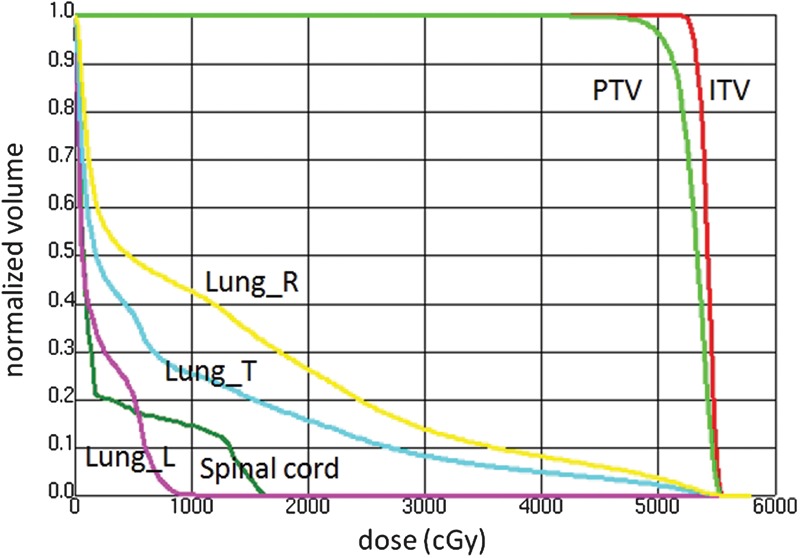
The CTV volume calculated by the 4D planning CT images were 6.83 cm3 for the maximum inhalation phase and 7.11 cm3 for the maximum exhalation phase. The volumes of the ITV and PTV were 11.51 cm3 and 34.61 cm3, respectively. Figure 1 depicts a resulting DVH and Table 1 shows more detailed dose calculation results for the defined structure set for the maximum exhalation and the maximum inhalation phase images, where L, R and T denote left, right and total, respectively. It was observed that the initial dose constraints were not fully satisfied; however, we concluded the result was clinically acceptable.
Fig. 1.

A dose volume histogram calculated by a single-arc VMAT plan for a lung tumor at the maximum exhalation phase.
The plan was created on the maximum exhalation 3D CT images using Pinnacle SmartArc with a maximum multi-leaf collimator leaf speed of 1 mm/degree thereby leading to quasi-conformal field shapes while optimizing each beam intensity for each gantry angle. L, R and T denote left, right and total, respectively.
Table 1.
Calculated doses in cGy and percentage dose-volume factors (V5, V10, V20) for the maximum exhalation and maximum inhalation phases, where Vx stands for a percentage volume receiving at least x Gy
| Expiration | Inspiration | |
|---|---|---|
| PTV_min | 4188.0* | 4051.7 |
| PTV_max | 5624.6 | 5661.8 |
| ITV_min | 5256.2 | 5055.1 |
| ITV_max | 5624.6 | 5661.8 |
| MLD_L | 213.7 | 214.5 |
| MLD_R | 1272.2 | 1214.9 |
| MLD_T | 843.8 | 831.8 |
| Lung_L_V20 | 0.00% | 0.00% |
| Lung_L_V10 | 0.00% | 0.00% |
| Lung_L_V5 | 21.35% | 21.64% |
| Lung_R_V20 | 26.49% | 24.42% |
| Lung_R_V10 | 42.45% | 41.18% |
| Lung_R_V5 | 49.17% | 48.48% |
| Lung_T_V20 | 15.77% | 15.07% |
| Lung_T_V10 | 25.28% | 25.43% |
| Lung_T_V5 | 37.91% | 38.01% |
| Spinal cord_max | 1655.4 | 1667.0 |
Treatment planning was performed using the maximum exhalation CT images. MLD=mean lung dose; L=left; R=right; T=total. *All doses are expressed in cGy units.
The measured isocenter dose in the lung phantom was 1340.0 cGy and the calculated isocenter dose was 1329.1 cGy. The isocenter dose discrepancy was 0.82% which was within measurement precision.
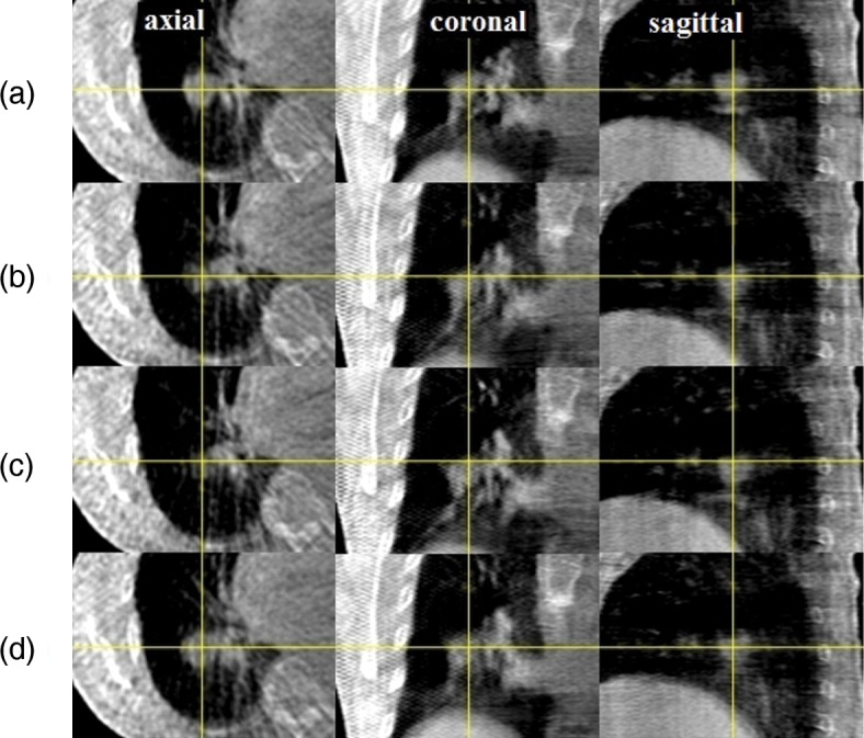
For this patient, VMAT delivery required 4 min 30 s with a total MU of 2010. The calculated isocenter dose was 5121.7 cGy for a prescribed D95 of 5000 cGy. Figure 2 shows respiratory correlated CBCT images of the lung tumor patient during VMAT delivery in four different respiratory phases: (a) maximum exhalation, (b) mid inhalation, (c) maximum inhalation and (d) mid exhalation. The cross lines indicate the isocenter. The tumor size in the cranio–caudal direction was approximately 2 cm whereas the tumor displacement in the cranio–caudal direction was approximately 1 cm. The respiratory movement was relatively insignificant because a body frame was employed.
Fig. 2.

Kilovoltage CBCT images of a lung tumor patient during VMAT delivery in different respiratory phases. (a) maximum exhalation, (b) mid inhalation, (c) maximum inhalation and (d) mid exhalation. Projection images were sorted into four respiration phase bins prior to CBCT reconstruction using image cross-correlation. The cross lines indicate the isocenter. A body frame was used to constrain respiratory movement.
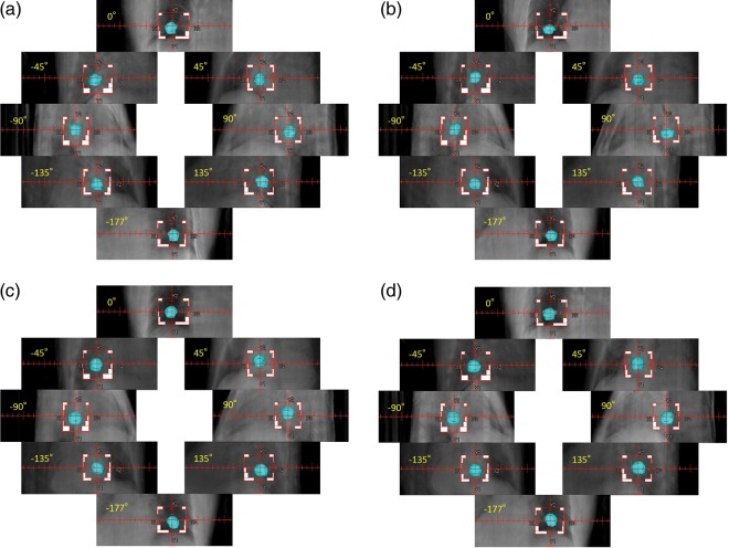
Figure 3(a) shows 4D DRRs as a function of gantry angle during VMAT delivery on the first day of the four-fraction lung radiotherapy. Because all the kilovoltage projection images were already sorted into four respiration phase bins to create four CBCT volumes, each gantry angle was related to one of the four CBCT volumes. As a result, respiratory correlated DRR was generated by each CBCT volume at each gantry angle. The MLC field shape and the isocenter were also shown in each DRR image. It was confirmed that the lung tumor remained inside each radiation field during VMAT delivery. Figure 3(b) to 3(d) show 4D DRR during VMAT delivery on the second, third and fourth day, respectively. Again, it was confirmed that the contoured CTV was inside the delivered field during each VMAT delivery.
Fig. 3.
(a) 4D digitally reconstructed radiographs (DRRs) as a function of gantry angle during VMAT delivery on the first day of the four-fraction lung radiotherapy; (b) 4D DRR during VMAT delivery on the second day, (c) on the third day and (d) on the fourth day. Because all the kilovoltage projection images were already sorted into four respiration phase bins to create four CBCT volumes, each gantry angle is related to one of the four CBCT volumes. As a result, respiratory correlated DRR was generated by each CBCT volume at each gantry angle. Prior to the DRR calculation, a clinical target volume (CTV) was added to each CBCT data by physicians delineating the tumor. The MLC field shape and the isocenter are also shown in each DRR image.
The 4D DRR images shown in Figs 3(a)–3(d) were created by 4D CBCT projection data acquired during VMAT delivery. Consequently, the actual spatial relationship between the tumor and the radiated field during entire VMAT delivery was precisely reproduced for the first time. It was found that the couch position in each fraction had some systematic deviation in the cranio–caudal direction, the cause being unknown to the authors. However, by detecting this deviation immediately after the first day delivery, it may be possible to adjust the plan for the remaining three fractions. This adaptive strategy may not be possible without obtaining 4D in-treatment delivery information.
Advantages of the quasi-conformal VMAT for a lung tumor may include shorter beam-on-time and lower monitor units compared with other beamlet-based VMAT or Intensity Modulated Radiation Therapy techniques, and much slower MLC leaf movements thereby possibly leading to a more accurate dose delivery. We believe that the body frame played an important role in this study to minimize the tumor motion and thus the defined PTV volume as well. The proposed method provides a practical way to verify the CTV positions during treatment; however, it is not a real-time position verification because the CTV in the DRR was based on the 4D CBCT projection data acquired during the VMAT delivery period of 4 min and 30 s.
We could not measure the dose distribution in the lung phantom with a film. This issue may be Elekta VMAT-specific because the machine parameters such as gantry speed and dose rate are automatically modified in the linac controller when delivered MUs are reduced. A solution may be to use a radiophotoluminescent glass plate with a linear dose response of up to 30 Gy [15].
In conclusion, 4D DRR has been proposed for the first time and it was confirmed that the contoured CTV was inside the radiated field during each four-fraction quasi-conformal VMAT treatment. 4D dose calculation using 4D CBCT during VMAT delivery is now under development in order to evaluate patient dose distributions more accurately. So far 20 lung tumor patients have been treated with the present technique.
CONFLICT OF INTEREST
Dr Nakagawa receives research funding from Elekta.
REFERENCES
- 1.Kaskowitz L, Graham MV, Emami B, et al. Radiation therapy alone for stage I non-small cell lung cancer. Int J Radiat Oncol Biol Phys. 1993;27:517–23. doi: 10.1016/0360-3016(93)90374-5. [DOI] [PubMed] [Google Scholar]
- 2.Nakagawa K, Aoki Y, Akanuma A, et al. Technological features and clinical feasibility of megavoltage CT scanning. Eur Radiol. 1992;2:184–9. [Google Scholar]
- 3.Nakagawa K, Aoki Y, Akanuma A, et al. Real-time beam monitoring in dynamic conformation therapy. Int J Radiat Oncol Biol Phy. 1994;30:1233–8. doi: 10.1016/0360-3016(94)90334-4. [DOI] [PubMed] [Google Scholar]
- 4.Nakagawa K, Aoki Y, Tago M, et al. Megavoltage CT-assisted stereotactic radiosurgery for thoracic tumors. Int J Radiat Oncol Biol Phy. 2000;48:449–57. doi: 10.1016/s0360-3016(00)00617-9. [DOI] [PubMed] [Google Scholar]
- 5.Lax I, Blomgren H, Näslund I, et al. Stereotactic radiotherapy of malignancies in the abdomen. Methodological spects. Acta Oncol. 1994;33:677–83. doi: 10.3109/02841869409121782. [DOI] [PubMed] [Google Scholar]
- 6.Blomgren H, Lax I, Näslund I, et al. Stereotactic high dose fraction radiation therapy of extracranial tumors using an accelerator. Clinical experience of the first thirty-one patients. Acta Oncol. 1995;34:861–70. doi: 10.3109/02841869509127197. [DOI] [PubMed] [Google Scholar]
- 7.Radiation therapy oncology group. A randomized phase II study comparing 2 stereotactic body radiation therapy (SBRT) schedules for medically inoperable patients with stage I peripheral non-small cell lung cancer, RTOG 0915. 2009 http://www.rtog.org/ClinicalTrials/ProtocolTable/StudyDetails.aspx?study=0915 (22 May 2012, date last accessed). [Google Scholar]
- 8.Nakagawa K, Yamashita H, Shiraishi K, et al. Verification of in-treatment tumor position using kilovoltage cone-beam computed tomography: a preliminary study. Int J Radiat Oncol Biol Phys. 2007;69:970–3. doi: 10.1016/j.ijrobp.2007.08.026. [DOI] [PubMed] [Google Scholar]
- 9.Nakagawa K, Haga A, Shiraishi K, et al. First clinical cone-beam CT imaging during volumetric modulated arc therapy. Radiother Oncol. 2009;90:422–3. doi: 10.1016/j.radonc.2008.11.009. [DOI] [PubMed] [Google Scholar]
- 10.Sonke JJ, Zijp L, Remeijer P, et al. Respiratory correlated cone beam CT. Med Phys. 2005;32:1176–86. doi: 10.1118/1.1869074. [DOI] [PubMed] [Google Scholar]
- 11.Sonke JJ, Remeijer P, van Herk M. Four dimensional cone beam CT acquisition concurrent with VMAT delivery. Radiother Oncol. 2010;96(Suppl 1):S75. [Google Scholar]
- 12.Nakagawa K, Kida S, Haga A, et al. Cone beam computed tomography data acquisition during VMAT delivery with subsequent respiratory phase sorting based on projection image cross-correlation, J Radiat Res. 2011;52:112–13. doi: 10.1269/jrr.10170. [DOI] [PubMed] [Google Scholar]
- 13.Kida S, Saotome N, Masutani Y, et al. 4D-CBCT reconstruction using MV portal imaging during volumetric modulated arc therapy. Radiother Oncol. 2011;100:380–5. doi: 10.1016/j.radonc.2011.08.047. [DOI] [PubMed] [Google Scholar]
- 14.Haga A, Nakagawa K, Shiraishi K, et al. Quality assurance of volumetric modulated arc therapy using Elekta Synergy. Acta Oncol. 2009;48:1193–7. doi: 10.3109/02841860903081905. [DOI] [PubMed] [Google Scholar]
- 15.Nakagawa K, Ishidoya T, Ikegami T, et al. A radiophotoluminescent glass plate system for medium-sized field dosimetry. Rev Sci Instr. 2005;76:106104. [Google Scholar]


