Abstract
Although natural silk fibers have excellent strength and flexibility, the regenerated silk materials generally become brittle in the dry state. How to reconstruct the flexibility for silk fibroin has bewildered scientists for many years. In the present study, the flexible regenerated silk fibroin films were achieved by simulating the natural forming and spinning process. Silk fibroin films composed of silk I structure were firstly prepared by slow drying process. Then the silk fibroin films were stretched in the wet state, following the structural transition from silk I to silk II. The difference between the flexible film and different brittle regenerated films was investigated to reveal the critical factors in regulating the flexibility of regenerated silk materials. Compared to the methanol-treated silk films, although having similar silk II structure and water content, the flexible silk films contained more bound water rather than free water, implying the great influence of bound water on the flexibility. Then, further studies revealed that the distribution of bound water was also a critical factor in improving silk flexibility in the dry state, which could be regulated by the nano-assembly of silk fibroin. Importantly, the results further elucidate the relation between mechanical properties and silk fibroin structures, pointing to a new mode of generating new types of silk materials with enhanced mechanical properties in the dry state, which would facilitate the fabrication and application of regenerated silk fibroin materials in different fields.
Keywords: silk, mechanical regeneration, flexibility, bound water
1. Introduction
Silk fibers from spiders and silkworms have aroused more and more interest in the field of materials due to their impressive mechanical properties and remarkable spinning process that converts water-soluble silk protein into insoluble solid silk fibers in physiological conditions.1–4 Compared with the high processing temperatures and/or hazardous solvents of the spinning process required for artificial polymers, the mild conditions of silk fiber formation such as room temperature and aqueous solution motivate the continuing attempts to improve the long-term performance of silk as a route to new engineering materials.5–8 Several attempts have been made to extrude silk artificially from redissolved fibroin or recombinant silk protein analogues, but the resulting fibers were considerably weaker and brittler than the natural fibers.9–12 On the other hand, silk fibroin also shows promising future applications in biomedical fields such as tissue engineering, drug release and even optical apparatus because of its excellent environmental stability, biocompatibility, and morphologic flexibility.13–18 Various silk-based materials from filament to film, sheet, and scaffold have been prepared to satisfy these applications through different ways.19–23 Unfortunately, these silk materials lose the flexibility in the dry state, which generates more practical difficulties in some applications. Recent study indicates that the excellent mechanical properties of silk fibroin are also related to the nanostructures of β-sheet crystal that are built up through self-assembly process in vivo.24, 25 However, the recapitulation of native silk fibroin dope and fiber properties in vitro from reconstituted silk solutions remains a challenge, particularly because controlled self-assembly of macromolecular components at the nanoscale is required.10 More detailed understanding of the way in which silkworms self-assemble into special nanostructures and then produce silk is necessary for designing a successful biomimetic artificial spinning method.
Silk I is a hydrated structure and is considered to be a necessary intermediate for the preorganization or preallignment of silk fibroin molecules. In recent studies, silk films mainly composed of silk I structure were prepared under physiological conditions by our group.22 In this study, flexible regenerated silk films containing similar nanostructure and secondary structure with natural silk fibers were achieved by stretching the silk films with silk I structure, facilitating the further applications of silk in various biomedical fields. The structural difference between the flexible silk films and the previous brittle silk films were elucidated, which would promote the understanding of the forming and spinning process of silk fiber in silkworm as well as the structure-function relationship of silk.
2. Materials and methods
2.1 Preparation of silk solutions
Silk solution were produced as described.22 Cocoons were boiled for 20 min in an aqueous solution of 0.02 M Na2CO3 and then rinsed thoroughly with distilled water to extract the sericin proteins. After drying, 13.5 g extracted silk fibroin was dissolved in 50 ml of LiBr solution (9.3 M) at 60°C for 4 h, yielding a 20% (w/v) solution. This solution was dialyzed against distilled water using Slide-a-Lyzer dialysis cassettes (Pierce, molecular weight cut-off 3,500) for 72 h to remove the salt. The solution was optically clear after dialysis and was centrifuged to remove the small amount of silk aggregates that formed during the process. The final concentration of aqueous silk solution was ~7 wt%, determined by weighing the remaining solid after drying.
2.2 Film formation
Silk films mainly composed of silk I structure were formed with a slower drying time of above 5 days according to our previous procedures.22 Then the films were hydrated in distilled water for approximately 30 min before clamping and then stretched to 200% of their original length at a crosshead speed of 5 mm min−1 using an Instron 3366 testing frame (Instron, Norwood, MA), resulting in the formation of silk II structure. The stretched silk films were dried in hood and become flexible in the dry state at room temperature. Water-insoluble films mainly composed of silk II structure were also prepared by the methanol annealing method, to serve as controls for the new stretched flexible films. In the methanol annealing process the soluble silk film prepared through quickly drying process was immersed in 80% methanol solution for about 1 h to increase the β-sheet content. The water-insoluble silk film prepared by slow drying is termed SD-SF, then the stretched silk film is termed SSD-SF, while the methanol-annealed film is termed MA-SF.
2.3 Fourier Transform Infrared Spectroscopy (FTIR)
The structural changes in the samples were analyzed using a JASCO FTIR 6200 spectrometer (JASCO, Tokyo, Japan) equipped with a MIRacle™ attenuated total reflection (ATR) Ge crystal cell in reflection mode. For each measurement, 32 scans were coded with a resolution of 4 cm−1, with the wavenumber ranging from 400 to 4000 cm−1.26
2.4 X-ray diffraction (XRD)
To investigate the structure and crystallinity of the samples, X-ray diffraction (XRD) experiments were also performed with an X-ray diffractometer (X′Pert-Pro MPD, PANalytical B.V. Holland) with CuKa radiation at 40 kV and 30 mA and scanning rate of 0.6/min.
2.5 Differential Scanning Calorimetry (DSC)
For DSC measurement, the samples were encapsulated in aluminum pans and heated in a TA Instruments Q100 DSC (TA Instruments, New Castle, DE) under a dry nitrogen gas flow of 50 ml/min. Temperature-modulated differential scanning calorimetry (TMDSC) measurements were performed using a TA instrument Q100 equipped with a refrigerated cooling system. The samples were heated at 2°C/min from −30°C to 350°C with a modulation period of 60 s and temperature amplitudes of 0.318°C.26
2.6 Thermogravimetric measurements
The water content of different silk films was determined from thermogravimetric measurements (TGA), using a TA 500Q system. Samples were heated to 550°C with a step increase of 2°C min−1 under an inert nitrogen atmosphere.
2.7 Scanning Electron Microscopy (SEM)
The cross-sectional microstructure of different silk films was studied. Specimens were fractured in liquid nitrogen to avoid deformation and sputter-coated with platinum and then examined using a Zeiss Supra 55 VP SEM (Oberkochen, Germany).
2.8 Mechanical properties
The tensile properties of specimens (40×25×0.2 mm) were measured at a crosshead speed of 2 mm min−1 using an Instron 3366 testing frame (Instron, Norwood, MA) at 20°C, and 65% RH. The samples were glued on a paper frame and then mounted on Instron tensile tester, and average tensile properties from five specimens were measured. Ultimate tensile strength was the highest stress value attained during the test and the elongation to failure was the last data point before a >10% decrease in load.
3. Results and Discussion
3.1 Structure characteristics
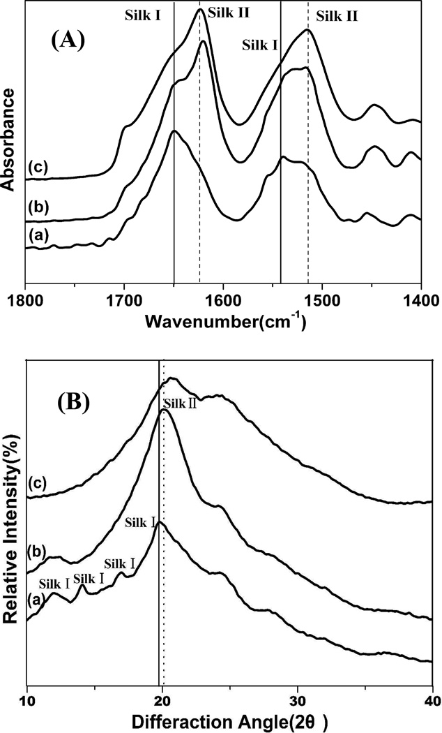
Structural changes in the silk films after the different processes were firstly determined by Fourier transform infrared-attenuated total reflection (FTIR-ATR) spectroscopy. The infrared spectral region within 1700–1500 cm−1 is assigned to absorption by the peptide backbones of amide I (1700–1600 cm−1) and amide II (1600–1500 cm−1), which have been commonly used for the analysis of different secondary structures of silk fibroin. The peaks at 1610–1630 cm−1 (amide I) and 1510–1520 cm−1 (amide II) are characteristic of silk II secondary structure while the absorptions at 1648–1654 cm−1 (amide I) and 1535–1545 cm −1 are indicative of silk I structure.22, 26–29 Similar with our previous study, the amide I and II bands for SD-SF showed strong peaks at 1652 and 1540 cm−1, corresponding to silk I structure (Fig 1A). After stretching treatment (SSD-SF), the bands shifted to 1619 and 1515 cm−1, respectively, which were similar with that of MA-SF. The results indicated that silk II structure formed after the stretching process. Interestingly, compared to MA-SF films, the amide I band for SSD-SF shifted from 1624 to 1619 cm−1, indicating more regular silk II structure formed in the SSD-SF films.
Figure 1.
FTIR spectra (A)and wide angle X-ray scattering (B) data for silk films prepared by different processes. (a) SD-SF, water-insoluble silk film prepared by slow drying, (b) SSD-SF, SD-SF was stretched to 200% of their original length, (c) MA-SF, methanol-annealed silk film
The structure of silk films formed using different processes was further characterized by X-ray diffraction. The corresponding d spacings for silk I and silk II are as follows (in nm): 0.98(II), 0.74(I), 0.56(I), 0.48(II), 0.44(I), 0.43(II), 0.41(I), 0.36(I), 0.32(I), 0.28(I).6, 30 In these d spacings the 0.74 nm peak occurs in a region of scattering space well removed from peaks found in the silk II structure. Therefore, the peak at a spacing near 0.74 nm is a strong evidence for silk I structure. As shown in Fig 1B, the SD-SF films were characterized by the presence of peaks at 11.5, 14.4,18.0 and 19.8°, corresponding to a silk I crystalline spacing of 0.71, 0.55, 0.44, and 0.40 nm. No typical diffraction peaks of silk II were found for the SD-SF film. After stretching treatment, the strength of silk I diffraction peaks at 11.5° decreased following the appearance of silk II diffraction peaks at 20.1°. The results are consistent with the FTIR results, confirming that silk I crystal transferred to silk II structure after stretching process. The FTIR and XRD results both indicated that similar silk II crystal structures formed for MA-SF and SSD-SF films.
3.2 Thermal analysis
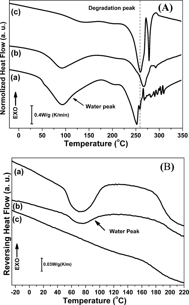
Fig 2A illustrated standard DSC curves for SD-SF, SSD-SF and MA-SF. The SD-SF samples showed an endothermic peak at around 90°C, and a degradation peak at 252°C while only degradation peak at 260°C appeared for the MA-SF films. Based on our previous study, the degradation peaks at 260°C and 252°C are related to stability induced by silk II and silk I structures, respectively.22 Therefore, the DSC results further confirmed the silk I formation in SD-SF and the silk II formation in MA-SF. The endothermic peak at around 90°C was due to the evaporation of bound water. Since silk I is a hydrated structure while silk II is a hydrophobic structure, a strong endothermic peak at around 90°C appeared for SD-SF but disappeared for MA-SF. More interesting results were found in the DSC curve of SSD-SF films. Although hydrophobic silk II structure formed, the SSD-SF still showed an endothermic peak at around 90°C, indicating that strong silk-water interaction maintained in the non-crystal regions of the SSD-SF films after silk I transferred into silk II in the stretching process. Compared to MA-SF, the SSD-SF films also showed higher degradation peak at 266°C, confirming that more regular and stabler β-sheet crystals formed in the SSD-SF films, which was consistent with the FTIR results. Although both the MA-SF and SSD-SF films are mainly composed of silk II structure, a balance between silk-bound water interaction and silk II structure formation achieved in the SSD-SF films, which might be useful to improve the mechanical properties of silk films in the dry state.
Figure 2.
Standard DSC scans (A) and TMDSC, temperature-modulated DSC scans (B) for silk films prepared by different processes. The samples are as follows: (a) SD-SF, water-insoluble silk film prepared by slow drying, (b) SSD-SF, SD-SF was stretched to 200% of their original length, (c) MA-SF, methanol-annealed silk film
The presence of silk-bound water interaction in the SSD-SF films was further confirmed through TMDSC (Fig 2B and Table 1). Our previous studies revealed that Tg at 60–80°C provided information about the removal of bound water, indicating the interaction strength between silk and bound water while the area of the endothermic peak was related to the amount of the bound water.4, 22 The MA-SF had no endothermic peak, meaning that little water formed strong interaction with the silk protein. The Tg was found for both SD-SF and SSD-SF, with a higher Tg but lower peak area at Tg being achieved for the SSD-SF (Table 1). The results indicated that part of the silk-bound water interaction was destroyed but the others was further improved after the stretching process, resulting in the amount decrease of bound water and the increase of Tg.
Table 1.
Silk-bound water interaction changes derived from TMDSC
| Silk Film | Tg(°C) | Δ Cp (J • g−1 • °C−1) |
|---|---|---|
| Slow Drying Film (SD-SF) | 48.90 | 0.13 |
| Stretched Slow Drying Film (SSD-SF) | 58.07 | 0.11 |
| Methanol-Annealed Film (MA-SF) | — | 0.06 |
3.3 Morphology
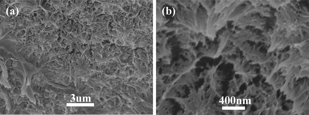
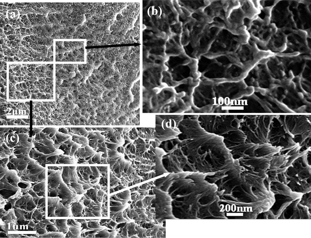
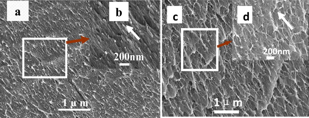
The silk films prepared by different ways had various nanostructures though all the films were composed of nano-filaments. The nano-filaments insides MA-SF assembled to irregular particles. Many interspaces formed between the particles (Fig 3). Compared to MA-SF, SD-SF formed more complicated nano-structures. The nano-filaments assembled to form globules (200–1000 nm in diameter) that were connected through entangled random nanofilaments(Fig 4). The diameter of the nano-filaments inside the globules was 10–20 nm, different from outside globules where the feature sizes were about 20–80 nm in diameter. After stretching, the globules were deformed and orientated in a way which the random nanofilaments outside the globules achieved better orientation than that inside the globules(Fig 5). All the feature sizes of the nanofilaments were decreased to about 10 nm, which is similar to that inside the MA-SF films. Compared MA-SF, SD-SF, and SSD-SF, most regular and compact structures were achieved in SSD-SF, which might be useful to improve the mechanical properties of the films.
Figure 3.
SEM images of the methanol-annealed silk films (MA-SF): (a) low magnification, (b) high magnification
Figure 4.
The typical cross section structure of silk films prepared by slow drying (SD-SF): (a) different structures existed in SD-SF; (b) higher magnification of outer layer of micelles; (c) and (d), the higher magnification of core of micelles
Figure 5.
Scan electron micrographs of the stretched silk films (SSD-SF): (a) and (b), the alignment and deformation of filaments composed of outer layer of micelles; (c) and (d), the alignment and deformation of filaments composed of core of micelles; and e, the formation fo aligned filaments with diameter size about 10nm that similar with natural silk filaments.
3.4 Mechanical properties
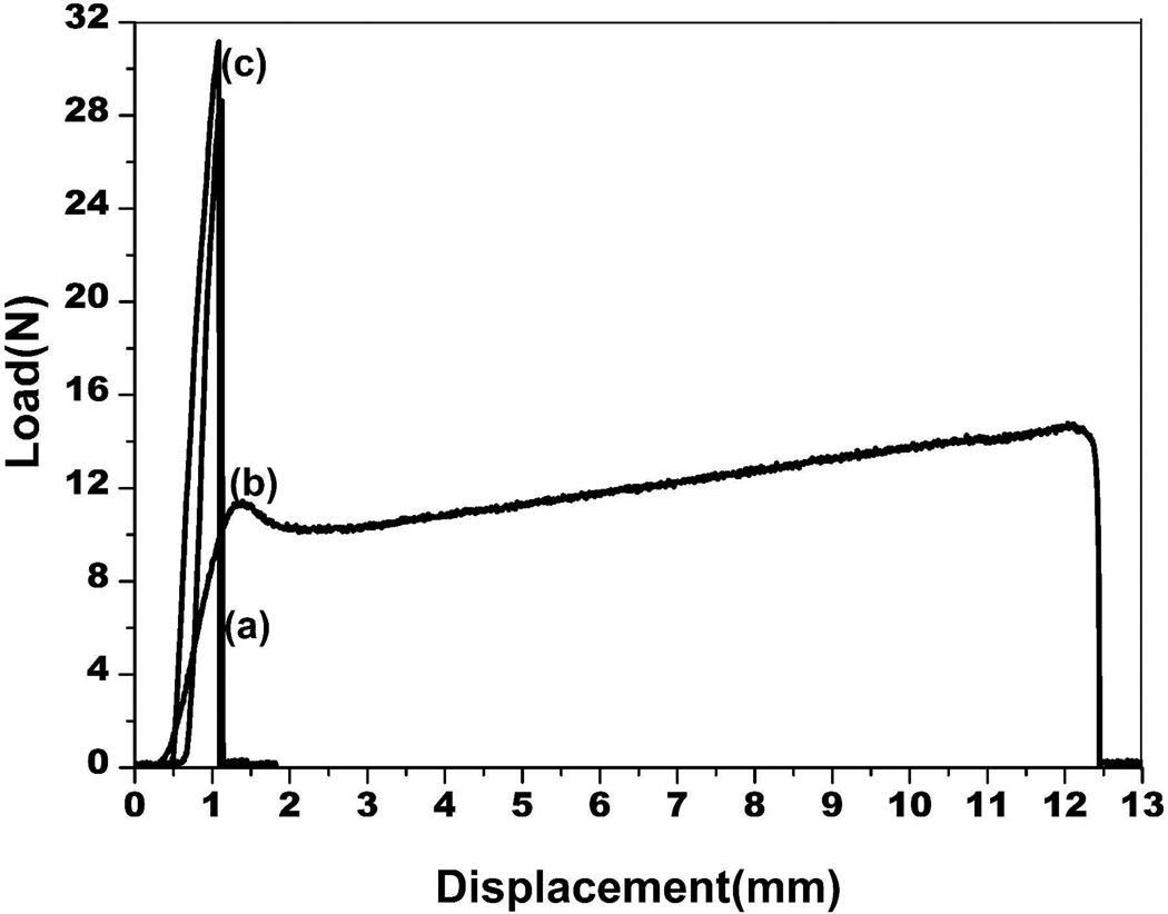
The mechanical properties of the different silk films (SD-SF, SSD-SF, and MA-SF) were measured in the dry state. Natural silk fibers have strong strength and good extensibility in dry state at room temperature, but the regenerated silk films such as SD-SF and MA-SF are generally brittle under the same conditions (Fig 6 and Table 2). Although the strength of SSD-SF was inferior to that of natural silk fibers, the SSD-SF films really became flexible in the dry state, indicating that it is possible to achieve extensibility for the regenerated silk materials through controlling the nanostructures and secondary conformations.
Figure 6.
The mechanical curves for silk films prepared by different processes in the dry state at room temperature. (a) SD-SF, water-insoluble silk film prepared by slow drying, (b) SSD-SF, SD-SF was stretched to 200% of their original length, (c) MA-SF, methanol-annealed silk film
Table 2.
Mechanical properties of silk films prepared by different processes(n = 5, average ± standard deviation)
| Silk Film | Tensile Strength(MPa) | Elongation at Break (%) |
|---|---|---|
| Slow Drying Film (SD-SF) | 32.1±2.4 | 3.6±0.1 |
| Stretched Slow Drying Film (SSD-SF) | 16.9±4.2 | 39.8±3.7 |
| Methanol-Annealed Film (MA-SF) | 31.8±0.9 | 4.3±0.8 |
| Natural Silk Fibers7 | 500 | 15 |
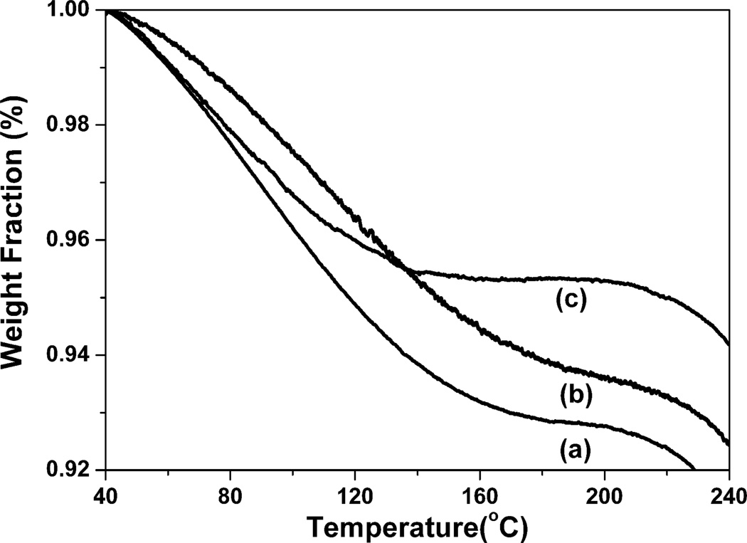
Why natural silk fibers have good extensibility but the regenerated silk materials are generally brittle has baffled researchers for many years. As we know, water has an important effect on silk mechanical properties. It can act as a plasticizer and incorporate into the silk structure to increase flexibility and extensibility. Most of regenerated silk materials could achieve the flexibility through increasing water content. However, since most of the water evaporated from the films in the dry state at room temperature, the films generally become fragile. Interestingly, SSD-SF still maintained flexibility in the dry state although the water content in SSD-SF (about 4.5%) was less than that in MA-SF (6.3%) (Fig 7). Since the TG results showed the amount of free and bound water while the DSC results reflected the amount of bound water, the difference about water content derived from DSC and TG results implied the changes of silk-bound water interactions among the samples. Considering that little bound water existed in MA-SF but strong interaction formed between the water and silk in SSD-SF (Fig 2), the present study indicated that besides water content, the binding strength between silk and water was also critical for the extensibility. The function of water was further confirmed by the heat-treated SSD-SF films. The flexible SSDSF transformed into brittle film when cultured for above 1 h at 70°C to remove some bound water. After the treated films were placed at room temperature for about 1 h to retrive the original silk-water interaction, the films achieved the flexibility again.
Figure 7.
TGA curves for silk films prepared by different processes. The samples are as follows: (a) SD-SF, water-insoluble silk film prepared by slow drying, (b) MA-SF, methanol-annealed silk film, (c) SSD-SF, SD-SF was stretched to 200% of their original length
On the other hand, SD-SF contained more bound water than SSD-SF, but was still brittle in the dry state. The results imply that there are other underlying factors in determining silk flexibility. As shown in Fig 4–5, both SD-SF and SSD-SF were composed of nanofibers in which more regular and oriented structures formed in the SSD-SF films. In our previous study, it was found that most of hydrophilic blocks distributed outside the globules in the SD-SF films, and then most of bound water also existed outside the globules rather than uniformly distributed. After stretched, the SSD-SF films formed the oriented nanofibers, which could increase the uniform distribution of bound water. In the wet state, enough water entered into silk fibroin materials as plasticizer, endowing the regenerated silk fibroin flexibility. Following the removal of free water in the dry state, the uneven distribution of bound water in the SD-SF films resulted in the loss of flexibility though more bound water existed in the films as compared with that in the SSD-SF films. Although there is no method to study the distribution of bound water inside silk films, other recent studies have confirmed that the nanostructure and arrangement of the nanofibers is critical for the formation of hydrogen bands and then the increase of the mechanical properties.24 Since SSD-SF also became brittle after the bound water evaporated, it is reasonable to believe that the distribution of bound water has great influence on silk flexibility. Previous studies have indicated that bound water mainly existed amorphous regions. It was believed that other factors such as crystallinity, domain size of crystalline region, distribution of crystallinity, and arraignment of amorphous region, indirectly implied the distribution of bound water inside silk films. Therefore, the flexibility improvement of silk fibroin in the dry state not only relies on the amount of bound water, but is also related to the distribution of the bound water, which could be controlled through regulating the nano-assembly of silk fibroin.
4. Conclusion
Water insoluble silk films with silk I structure were firstly prepared through slow drying process. Then the flexible silk films were achieved after stretching the water insoluble films in the wet state, following the structural transition from silk I to silk II. Comparing the flexible silk films to previous brittle regenerated films, it was believed that the flexibility was related to the content of bound water as well as the distribution of bound water. Through regulating the nanostructure and secondary conformations of silk fibroin in silk assembly process, the content and distribution of bound water could be regulated, making it possible to further improve the mechanical properties of silk fibroin in the dry state. Considering promising applications of flexible silk films in different high-technology directions such as tissue regeneration, drug release, optical devices and flexible electronic displays, the present study provides an effective way to achieve the mechanical regeneration of silk fibroin in vitro, which would further facilitate the applications of silk fibroin in the different fields.
Acknowledgements
We thank the Priority Academic Program Development of Jiangsu Higher Education Institutions (PAPD) and National Natural Science Foundation of China (21174097) for support of this work. We also thank the NIH, Ph.D. Programs Foundation of Ministry of Education of China(201032011200009), and the Key Natural Science Foundation of the Jiangsu Higher Education Institutions of China(11KGA430002) for support of this work.
References
- 1.Hagn F, Eisoldt L, Hardy JG, Vendrely C, Coles M, Scheibel T, Kessler H. Nature. 2010;465:239–242. doi: 10.1038/nature08936. [DOI] [PubMed] [Google Scholar]
- 2.Askarieh G, Hedhammar M, Nordling K, Saenz A, Casals C, Rising A, Joansson J, Knight SD. Nature. 2010;465:236–238. doi: 10.1038/nature08962. [DOI] [PubMed] [Google Scholar]
- 3.Plaza GR, Corsini P, Marsano E, Perez-Rigueiro J, Elices M, Riekel C, Vendrely C, Guinea GV. J. Polym. Sci. Pol. Phys. 2012;50:455–465. [Google Scholar]
- 4.Lu Q, Zhu HS, Zhang CC, Zhang F, Zhang B, Kaplan DL. Biomacromolecules. 2012;13:826–832. doi: 10.1021/bm201731e. [DOI] [PMC free article] [PubMed] [Google Scholar]
- 5.Eisoldt L, Smith A, Scheibel T. Mater. Today. 2011;14:80–86. [Google Scholar]
- 6.Jin HJ, Kaplan DL. Nature. 2003;424:1057–1061. doi: 10.1038/nature01809. [DOI] [PubMed] [Google Scholar]
- 7.Shao Z, Vollrath F. Nature. 2002;418:741–741. doi: 10.1038/418741a. [DOI] [PubMed] [Google Scholar]
- 8.Matsumoto A, Lindsay A, Abedian B, Kaplan DL. Macromol. Biosci. 2008;8:1006–1018. doi: 10.1002/mabi.200800020. [DOI] [PubMed] [Google Scholar]
- 9.Elices M, Guinea GV, Plaza GR, Karatzas C, Riekel C, Agullo-Rueda F, Ddaza R, Perez-Rigueiro J. Macromolecules. 2011;44:1166–1176. [Google Scholar]
- 10.Omenetto FG, Kaplan DL. Science. 2010;329:528–531. doi: 10.1126/science.1188936. [DOI] [PMC free article] [PubMed] [Google Scholar]
- 11.Weisman S, Haritos VS, Church JS, Huson MG, Mudie ST, Rodgers AJW, Dumsday GJ, Sutherland TD. Biomaterials. 2010;31:2695–2700. doi: 10.1016/j.biomaterials.2009.12.021. [DOI] [PubMed] [Google Scholar]
- 12.Yan JP, Zhou GQ, Knight DP, Shao ZZ, Chen X. Biomacromolecules. 2010;11:1–5. doi: 10.1021/bm900840h. [DOI] [PubMed] [Google Scholar]
- 13.Altman GH, Diaz F, Jakuba C, Calabro T, Horan RL, Chen JS, Lu H, Richmond J, Kaplan DL. Biomaterials. 2003;24:401–416. doi: 10.1016/s0142-9612(02)00353-8. [DOI] [PubMed] [Google Scholar]
- 14.Marolt D, Augst A, Freed LE, Vepari C, Fajardo R, Patel N, Gray M, Farley M, Kaplan DL, Vunjak-Novakovic G. Biomaterials. 2006;27:6138–6149. doi: 10.1016/j.biomaterials.2006.07.015. [DOI] [PubMed] [Google Scholar]
- 15.Zhang YF, Fan W, Ma ZC, Wu CT, Fang W, Liu G, Xiao Y. Acta Biomater. 2010;6:3021–3028. doi: 10.1016/j.actbio.2010.02.030. [DOI] [PubMed] [Google Scholar]
- 16.Wang Y, Bella E, Lee CSD, Migliaresi C, Pelcastre L, Schwartz Z, Boyan BD, Motta A. Biomaterials. 2010;31:4672–4681. doi: 10.1016/j.biomaterials.2010.02.006. [DOI] [PubMed] [Google Scholar]
- 17.Huang S, Fu XB. J. Controlled Release. 2010;142:149–159. doi: 10.1016/j.jconrel.2009.10.018. [DOI] [PubMed] [Google Scholar]
- 18.Harkin DG, George KA, Madden PW, Schwab IR, Hutmacher DW, Chirila TV. Biomaterials. 2011;32:2445–2458. doi: 10.1016/j.biomaterials.2010.12.041. [DOI] [PubMed] [Google Scholar]
- 19.Zhang F, Zuo BQ, Fan ZH, Xie ZG, Lu Q, Zhang XG, Kaplan DL. Biomacromolecules. 2012;13:798–804. doi: 10.1021/bm201719s. [DOI] [PMC free article] [PubMed] [Google Scholar]
- 20.Lu Q, Wang XL, Lu SZ, Li MZ, Kaplan DL, Zhu HS. Biomaterials. 2011;32:1059–1067. doi: 10.1016/j.biomaterials.2010.09.072. [DOI] [PMC free article] [PubMed] [Google Scholar]
- 21.Lu Q, Zhang XH, Hu X, Kaplan DL. Macromol. Biosci. 2010;10:289–298. doi: 10.1002/mabi.200900258. [DOI] [PubMed] [Google Scholar]
- 22.Lu Q, Hu X, Wang XQ, Kluge JA, Lu SZ, Cebe P, Kaplan DL. Acta Biomater. 2010;6:1380–1387. doi: 10.1016/j.actbio.2009.10.041. [DOI] [PMC free article] [PubMed] [Google Scholar]
- 23.Yuan QQ, Yao JR, Shao ZZ. Acta Polym. Sin. 2011;11:1329–1335. [Google Scholar]
- 24.Keten S, Xu Z, Ihle B, Buehler MJ. Nat. Mater. 2010;9:359–367. doi: 10.1038/nmat2704. [DOI] [PubMed] [Google Scholar]
- 25.Nova A, Keten S, Pugno NM, Redaelli A, Buehler MJ. Nano Lett. 2010;10:2626–2634. doi: 10.1021/nl101341w. [DOI] [PubMed] [Google Scholar]
- 26.Hu X, Kaplan DL, Cebe P. Macromolecules. 2006;39:6161–6170. [Google Scholar]
- 27.Jin HJ, Park J, Karageorgiou V, Kim UF, Valluzzi R, Cebe P, Kaplan DL. Adv. Funct. Mater. 2005;15:1241–1247. [Google Scholar]
- 28.Um IC, Kweon HY, Park YH, Hudson S. Int. J. Biol. Macromol. 2001;29:91–97. doi: 10.1016/s0141-8130(01)00159-3. [DOI] [PubMed] [Google Scholar]
- 29.Wilson D, Valluzzi R, Kaplan DL. Biophys. J. 2000;78:2690–2701. doi: 10.1016/S0006-3495(00)76813-5. [DOI] [PMC free article] [PubMed] [Google Scholar]
- 30.Anderson JP. Biopolymers. 1989;4:361–372. [Google Scholar]


