Abstract
Purpose
To demonstrate the feasibility of a dedicated breast computed tomography (bCT) platform to deliver rotational kilovoltage external beam radiation therapy (kVEBRT) for partial breast irradiation (PBI), whole breast irradiation (WBI) and dose painting.
Methods and Materials
Rotational kV-EBRT using the geometry of a prototype bCT platform was evaluated via Monte Carlo simulator. A point source emitting 178 keV photons (approximating a 320 kVp spectrum with 4 mm copper filtration) was rotated around a 14 cm voxelized polyethylene disk (0.1 cm tall) or cylinder (9 cm tall) to simulate primary and primary plus scattered photon interactions, respectively. Simulations were also performed using voxelized bCT patient images. Beam collimation was varied in the x-y plane (1–14 cm) and in the z-direction (0.1–10 cm). Dose painting for multiple foci, line and ring distributions was demonstrated using multiple rotations with varying beam collimation. Simulations using the scanner’s native hardware (120 kVp filtered by 0.2 mm copper) were validated experimentally.
Results
As the x-y collimator was narrowed, the 2D dose profiles shifted from a cupped profile with high edge dose to an increasingly peaked central dose distribution with sharp dose fall-off. Using a 1 cm beam, the cylinder edge dose was less than 7% of dose deposition at the cylinder center. Simulations using 120 kVp x-rays showed distributions similar to experimental measurements. A homogeneous dose distribution (< 2.5% dose fluctuation) with a 20% decrease in dose deposition at the cylinder edge (i.e. skin sparing) was demonstrated by weighted summation of four dose profiles using different collimation widths. Simulations using patient bCT images demonstrated the potential for treatment planning and image-guided radiation therapy (IGRT).
Conclusions
Rotational kV-EBRT for PBI, dose painting, and WBI with skin sparing is feasible on a bCT platform with the potential for high-resolution IGRT.
Keywords: breast cancer, rotational kilovoltage radiation therapy, computed tomography, Monte Carlo simulation
I. Introduction1
Dedicated breast computed tomography (bCT) is an experimental fully tomographic cone-beam x-ray based imaging modality that generates three-dimensional images of the pendant breast (1). While most research has focused on the potential of bCT in diagnostic breast imaging, we propose the use of the bCT platform as a system for image-guided external beam radiation therapy (EBRT).
Breast radiotherapy is traditionally delivered using 6 MV photons on linear accelerator equipment that is substantially larger and more complicated than existing prototype bCT platforms (2, 3). We propose the use of kilovoltage spectra (~320 kVp) and rotational summation of a collimated x-ray beam to deliver therapeutic dose distributions within the geometric constraints of a bCT platform. While megavoltage photons are beneficial given their characteristic depth-dose build-up region and skin-sparing properties, equivalent skin sparing may be achieved from rotational summation of a collimated kilovoltage beam, as described in published dose distribution atlases (4).
The ability to deliver radiation therapy, be it whole breast irradiation (WBI) or partial breast irradiation (PBI), on a platform originally designed and optimized for diagnostic breast imaging, makes a dedicated bCT platform capable of kilovoltage EBRT (kV-EBRT) ideally positioned for image-guided radiation therapy (IGRT). Tumor targeting, treatment planning, and treatment delivery on a similarly-designed high-resolution device has the potential to reduce patient repositioning error and improve treatment accuracy (5). Simultaneous imaging during treatment may also be possible.
The purpose of this study was to demonstrate, through Monte Carlo simulation, the feasibility of a dedicated bCT platform to deliver rotational kVEBRT for PBI, WBI and dose painting applications.
II. Materials and Methods
II.A. Monte Carlo Simulation Geometry
Rotational kV-EBRT was simulated using Monte Carlo N-Particle Extended radiation transport code (MCNPX 2.6.0). The simulation geometry was based on a prototype bCT platform with a 51.1 cm source-to-isocenter distance (1). A point radiation source was simulated to generate a collimated x-ray beam which was rotated around the isocenter at one degree increments for a total of 360 degrees; the resulting simulation outputs were combined to represent a complete rotation. A 14 cm diameter polyethylene disk or cylinder (0.9325 g/ml) was placed at isocenter to represent a pendant breast (or breast segment) of average diameter (Figure e1) (6), based on its similar x-ray attenuation properties as compared to adipose tissue (7). Photon and electron transport was tracked and normalized to the number of incident photons.
II.B. Photon Energy Selection
A 320 kVp x-ray spectrum filtered by 4 mm of copper (half value layer – HVL – of 4.4 mm Cu), to attenuate the tungsten K-edges and to harden the x-ray beam, was generated with MCNPX using point detectors and 1 keV energy bins (Figure e2). A 320 kVp photon source was selected based on the availability of kilovoltage tungsten anode x-ray tubes which are small enough to abut the treatment couch to treat the posterior aspect of the breast (2). For simulation simplicity, 178 keV monoenergetic photons were used to approximate the 320 kVp spectrum, as demonstrated by simulation of their depth dose characteristics in 14 cm of polyethylene (Figure e3).
II.C. 2D and 3D Dose Distributions
Two-dimensional dose profiles were generated using a thin voxelized disk (0.1 cm tall) placed at isocenter to simulate primary photon interactions. A cylinder (9 cm tall) with a central voxelized cross-section (0.1 cm thick) was used to simulate the interactions of primary and scattered photons (Figure e1a). In both cases, the voxelized section consisted of 0.1 cm isotropic voxels. Beam collimation was set to 0.1 cm in the z-direction and was varied from 1 to 14 cm in the x-y plane of rotation, as measured at isocenter.
To generate three-dimensional dose distributions, a 14 cm diameter cylinder was placed at isocenter and fully voxelized using 0.5 cm isotropic voxels (Figure e1b). Z-collimation was 2 cm and x-y collimation was 1, 7 or 14 cm.
II.D. Experimental Validation
Experimental validation was performed on the same prototype bCT scanner that was used to model the simulation geometry. This unit employs a tungsten anode x-ray tube with a maximum tube potential of 120 kVp, filtered by 0.2 mm of copper. An adjustable four-leaf tungsten collimator was used to collimate the x-ray beam to 1, 7, and 14 cm in the x-y plane and to 3 cm in the z-direction.
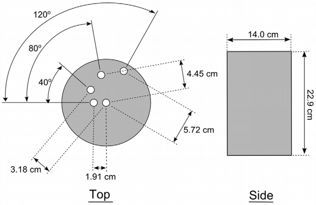
A 14 cm diameter polyethylene cylinder (22.9 cm tall) with 1.27 cm diameter cylindrical columns bored out at radial distances of 0 (center), 1.91, 3.18, 4.45, and 5.72 cm was used to measure radial dose profiles during a complete rotation of the x-ray source (Figure 1). Exposure was measured at each position using a Farmer-type air ionization chamber (RadCal 9010). Relative kerma measurements were made using a prototype scintillator-based real-time dose probe (Diagnostic Imaging Specialists Corporation) (8).
Figure 1.
Cylinder phantom used for relative kerma measurements.
Corresponding Monte Carlo simulations were generated with the same geometry and a 120 kVp polyenergetic x-ray spectrum derived using TASMIP(9) and calibrated to match the HVL measured on the scanner.
II.E. Scattered Photon Simulations
The scatter-to-primary ratio in the x-y plane of rotation was evaluated as a function of increasing z-collimation (0.1, 1.0, 2.5, 5.0, and 10.0 cm) by comparing linear profiles across the 2D dose distributions of primary and scattered photon interactions. The dose from scattered photons was calculated as the difference in the primary only and scattered plus primary dose distributions.
Scatter tails in the z-direction were evaluated by irradiating a 9 cm tall cylinder containing a central column of 0.1 cm thick voxels (1 by 1 cm x-y dimension). The x-ray beam was collimated to 2 cm in the z-direction and x-y collimation was set to 2, 7, or 14 cm. Dose deposition from primary x-rays (178 keV) and scattered x-rays (<178 keV) was tracked.
II.F. Dose Painting
Dose painting was demonstrated using multiple rotations of a 0.5–1.0 cm x-y collimated beam around a 14 cm polyethylene disk. The center of rotation was shifted for each rotation. Two off-center foci were irradiated with a 1.0 cm and 0.5 cm x-y collimated beam and center of rotation at 2.8 cm and 3.6 cm from the cylinder center, respectively. A line distribution was simulated using a 0.5 cm beam rotated seven times, with the center of rotation translated by 0.5 cm in the x-direction for each rotation. A ring distribution was simulated using a 1.0 cm beam with an inner beam stopper to block a 0.5 cm wide portion of the beam.
II.G. Whole Breast Irradiation
Whole breast irradiation, to deliver a homogeneous dose across the breast with skin sparing, was approximated by weighted summation of the 2D dose profiles measured in Section II.C. This is equivalent to multiple rotations with different collimation width and beam intensity at each rotation, to achieve a summative dose approaching WBI. Two-dimensional dose profiles were radially averaged and the radial profiles were fit piecewise using a cubic polynomial to represent the inner cupped portion of dose deposition and a power function to describe the dose tails extending outward (Table e1). The analytical fits were used to identify a subset of distributions (i.e. collimation widths) and weighting factors (i.e. intensities) for which the weighted sum approached a homogeneous distribution with skin sparing.
II.H. bCT Patient Simulations
Rotational kV-EBRT was simulated using images acquired on the bCT scanner to more accurately model breast tissue distribution, the attenuation of different breast tissues, and the presence of a lesion. Contrast-enhanced bCT (CE-bCT) images of the patient’s breast, containing an invasive mammary carcinoma, were acquired using typical technique factors (1, 10). A 3D segmentation method combining 3D median filtering, iterative thresholding, and a connected-components algorithm was used to segment the image data set into regions of air, skin, adipose tissue, and glandular tissue (including the malignant lesion) (11).
A slice of the segmented data set was used to define the material properties of a 512×512 lattice containing 0.1 cm thick voxels with x-y dimensions equal to those of the bCT images (0.346 mm). The breast tissues were defined by their elemental composition (12). The breast segment was sandwiched between polyethylene cylinders of equal effective diameter, achieving a total height of 9 cm. The object was irradiated using a 0.1 cm z-collimated and 2.0 cm (approximate lesion diameter) x-y collimated beam centered at the lesion.
III. Results
III.A. 2D and 3D Dose Distributions
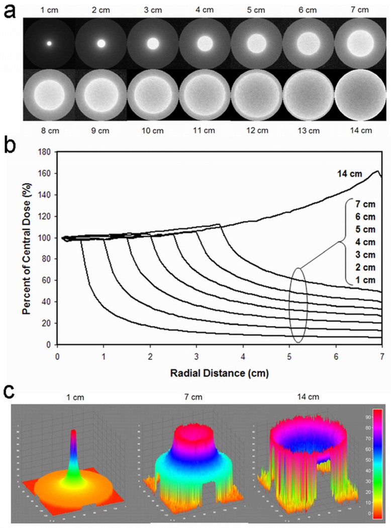
Simulations using a 14 cm beam resulted in a 2D dose distribution demonstrating a cupped profile, with high cylinder edge dose. As x-y collimation was narrowed, 2D dose profiles showed increasingly peaked central dose deposition with low edge dose (Figure 2).
Figure 2.
As x-y collimation increased from 1 cm to 14 cm, 2D dose distributions showed a widening focus of dose deposition with increased central cupping. Dose profiles are presented as 2D images (a), radial averages (b), and surface plots of percent maximum dose (c).
With 1 cm x-y collimation, the cylinder edge dose was less than 7% of maximum dose deposition (Figure 2b). The ratio of central dose to edge dose decreased with increasing x-y collimation width following a power-law relation; a 14 cm beam had a ratio of 0.64.
For 1 cm x-y collimation, the 90% isodose curve was less than 0.5 cm from isocenter while the 10% isodose curve was 3.4 cm from isocenter, approximately half the distance to the cylinder edge.
Three-dimensional dose distributions using 1 cm x-y collimation generated a focused cylindrical distribution, while a 14 cm beam generated a biconcave disk distribution. Intermediate collimation (7 cm) resulted in a hybrid saucer-shaped dose distribution.
III.B. Experimental Validation
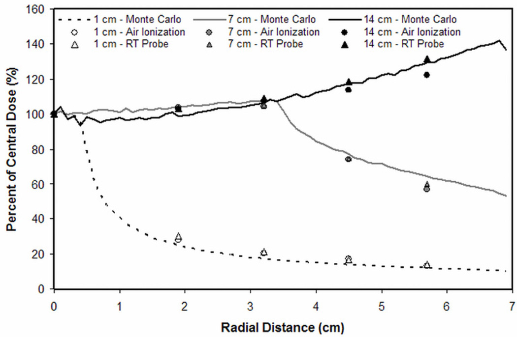
Experimental measurements of a collimated 120 kVp x-ray beam demonstrated similar radial dose distributions as simulations (Figure 3). The mean percent difference (± standard deviation) in radial dose deposition between simulations and measurements made using an air ionization chamber was 10.5 ± 7.7%, 4.1 ± 5.3%, and 2.8 ± 2.3%, for 1, 7 and 14 cm collimation widths, respectively. Using the real-time dose probe, mean percent differences were 13.7 ± 8.3%, 2.8 ± 2.8%, and 2.0 ± 1.7%, respectively.
Figure 3.
Relative kerma measurements performed on the prototype bCT scanner agreed with corresponding Monte Carlo simulations.
III.C. Scattered versus Primary Dose Deposition
As z-collimation was widened, the mean scatter-to-primary ratio across the cylinder increased to a maximum of 0.62 for an uncollimated beam. Z-collimation width of 2.5 cm yielded a scatter-to-primary ratio of 0.31.
For a constant 2 cm z-collimation width, as x-y collimation widened, the scatter tails in the z-direction increased; using 2, 7 and 14 cm x-y collimation the dose from z-direction scatter tails was 1.4%, 3.6%, and 5.0% of maximum dose, respectively, as measured at the cylinder top/bottom (Figure e4). At 0.5 cm above/below the treatment field, z-direction scatter tails were 7.4%, 14.4%, and 16.6% of maximum dose, respectively.
III.D. Dose Painting
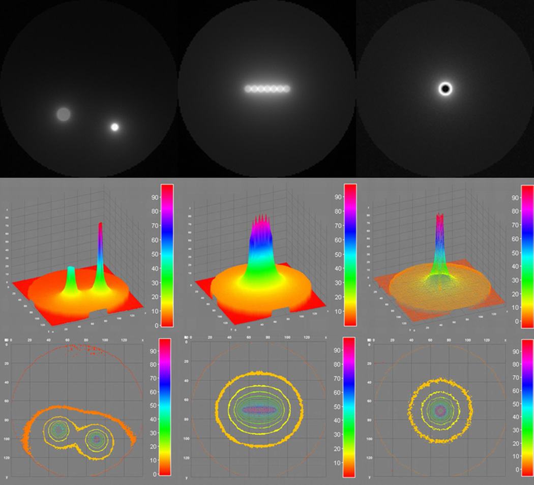
Irradiating two off-center foci resulted in approximately 5% of maximum dose deposition at the edge nearest the two foci (Figure 4).
Figure 4.
Dose painting for multiple off-center foci (left column), line (middle column) and ring distributions (right column) was achieved using multiple rotations with varying collimation width.
A line distribution resulted in oval isodose curves with 50% of maximum dose within 1 cm around the line distribution and approximately 10% of maximum dose 3 cm from the cylinder edge in the y-direction and 2.5 cm from the cylinder edge in the x-direction.
Isodose curves from a ring distribution were similar to those using a 1 cm collimated beam, but with central dose sparing.
III.E. Whole Breast Irradiation
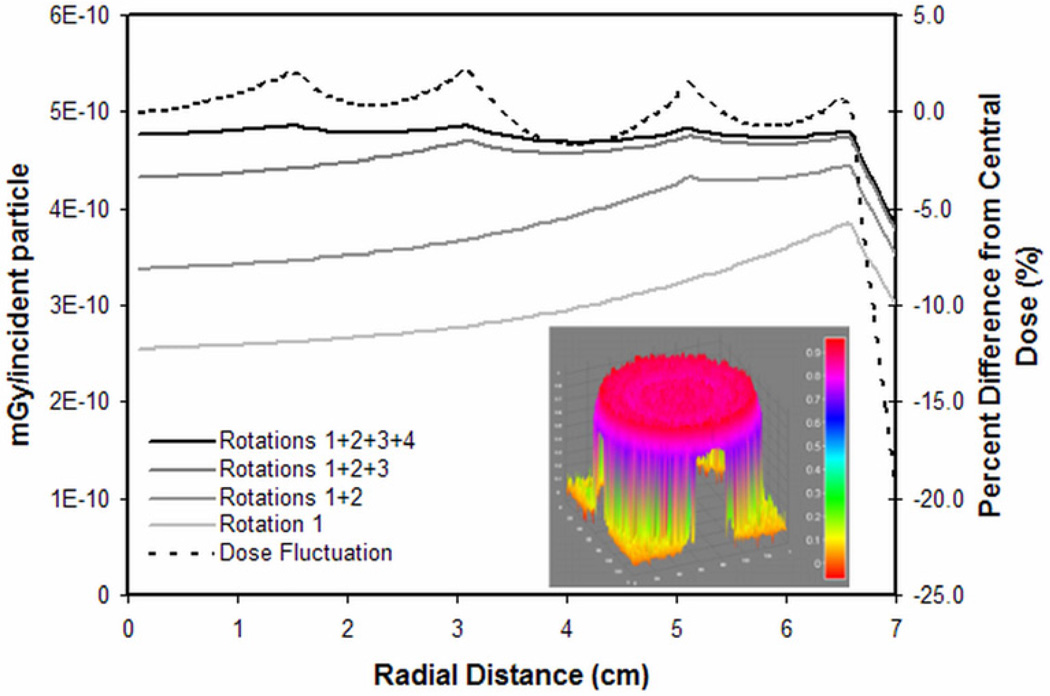
Using the dose distributions from the 13, 10, 6, and 3 cm x-y collimated beams, four weighting factors were identified (1, 0.25, 0.17, and 0.04, respectively) to achieve a near-homogenous summative dose. The summed dose distribution showed less than 2.5% deviation from the central dose up to 0.5 cm from the cylinder edge, where the dose decreased by 20% of the central dose (Figure 5). Using three rotations, x-y collimation widths of 13, 9, and 4 cm, and weighting factors of 1, 0.33, and 0.12, respectively, the summed dose fluctuated by less than 4% until a similar 20% dose drop-off at the cylinder edge.
Figure 5.
Weighted summation of four radial dose distributions (13, 10, 6, and 3 cm x-y collimation) approached a homogeneous dose distribution with skin sparing (solid black line). There was less than 2.5% variation until the drop off at the cylinder edge (dashed black line). The equivalent 2D surface rendering is presented in the inset.
III.F. bCT Patient Simulations
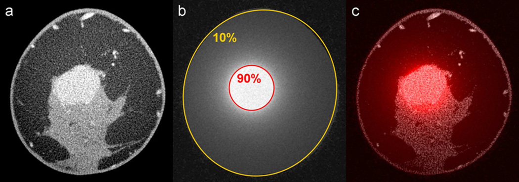
Simulations on CE-bCT images of a patient with an enhancing invasive mammary carcinoma (Figure 6a) used a breast segment with a 7.4 cm effective diameter. Rotation of a 2 cm x-y collimated x-ray beam about the center of the lesion resulted in focused dose deposition in the region of the lesion. The lesion was within the 90% isodose line and the skin received approximately 10% of the maximum dose (Figure 6b,c). Dose deposition in adipose and glandular tissue was similar.
Figure 6.
A contrast-enhanced bCT image containing an enhancing invasive mammary carcinoma (a) was used to simulate rotational kV-EBRT with 2 cm x-y collimation centered at the lesion. The resulting dose distribution (b) and the fusion image (c) are shown.
IV. Discussion
Kilovoltage rotational EBRT for the treatment of breast cancer is feasible on a dedicated bCT platform. Monte Carlo simulations demonstrated dose distributions for PBI, dose painting, and WBI with skin sparing.
A focus of dose can be deposited with rapid dose fall-off to the surrounding medium by using a highly collimated x-ray beam rotated about an isocentric focal point. In doing so, small volumes can be treated with the breast skin receiving a small fraction of the dose, as demonstrated by a 1 cm beam delivering less than 7% of maximum dose to the skin. Employing multiple rotations of a narrow beam with different centers of rotation allows for dose painting. Two off-center foci, a line distribution, and a ring distribution were simulated, but any dose distribution can be generated within the constraints of beam collimation accuracy, lesion proximity to the skin surface and chest wall, and total treatment time. Development of a bCT platform with a translating isocenter to allow for lesion-focused imaging and PBI is currently under way.
Whole breast irradiation was demonstrated by using multiple rotations with varying beam collimation width and intensity. A dose distribution with better than 2.5% homogeneity and a 20% decrease in dose near the skin was generated with only four rotations. It is expected that with more collimation widths, even better homogeneity can be achieved. The WBI distributions presented in this study were achieved by manually selecting collimation widths and weighting factors. Development of an optimum plan will rely on more sophisticated treatment planning algorithms to identify the optimal combination of collimation widths and beam intensities. Clinical feasibility of WBI employing this paradigm will require a bCT platform with a dynamic multi-leaf collimator, an x-ray source capable of rapid tube current modulation, and possibly a slip-ring gantry design for continuous source rotation. Such a design would allow for tube current modulation between rotations as well as within a rotation to account for patient anatomy, glandular tissue distribution, and lesion location. Intensity modulated radiation therapy (IMRT) on a bCT platform may allow for improved dose conformality and additional skin sparing (13).
Total treatment time for PBI or WBI will be a critical design constraint for the delivery of kV-EBRT on a bCT platform and will necessitate a high-power tube capable of delivering sufficient dose rates. Larger, stiffer high-voltage cables may require a wider system design. Technical data for a similar 320 kVp source (HVL ≈ 4 mm Cu) demonstrates dose rates of 1 Gy/min at 50 cm source-to-surface distance (SSD) (14). In megavoltage EBRT of the breast, typical dose rates (~500 cGy/minute) yield beam-on times of a couple of minutes; however, with patient set up and source repositioning, total treatment times can approach 15 minutes or more. The beam-on time of a kilovoltage source is expected to be longer for equal dose prescriptions, but the total procedure time may be similar due to the simplicity of patient and source positioning on the bCT platform.
In contrast to megavoltage radiation therapy, kilovoltage treatment beams will result in scattering events with a wide angular distribution. A 2 cm z-collimated WBI or PBI treatment beam focused on a lesion in the middle of an average length breast (6) resulted in a chest wall dose that is no greater than 5% of dose deposited near the lesion; however, more detailed simulations are needed to evaluate the dose deposited in the heart, lungs, and other critical organs when treating the breast with rotational kV-EBRT.
The simulations used in this study had inherent limitations. Monoenergetic x-rays were used and may have different scatter properties from the polyenergetic spectrum they modeled. The breast was modeled as a homogeneous cylinder. While simulations were performed on CE-bCT patient images, only one slice of the breast was simulated in a cylindrical geometry. Future studies using a fully-voxelized 3D data set of the entire breast would more accurately describe doses to the skin, glandular tissue, and chest wall. Visualization of the axillary tail with diagnostic bCT can be limited (1) and, consequently, kV-EBRT on the bCT platform may not deliver sufficient dose to treat lesions in the axilla or for nodal irradiation. However, improved table top design and novel patient positioning schemes unique to prone radiation therapy may allow for axillary therapy. Feasibility was evaluated by simulation, but experimental validation showed similar results. Experimental variation in relative dose deposition is likely due to the energy dependence of the dosimeters in response to the varying spectral energy distribution in the cylinder from x-ray scattering and attenuation.
Despite these limitations, the simulations presented in this study suggest that the bCT platform has potential to deliver rotational kV-EBRT for the treatment of breast cancer. Rotational kV-EBRT on a bCT platform may offer several benefits over traditional supine megavoltage breast radiotherapy. Preliminary studies of prone megavoltage therapy suggest that prone positioning decreases respiratory motion (15) and reduces heart and lung doses, particularly in large breasted women and when treating the right breast (16). Prone positioning on the bCT platform may provide the same benefits as well as improved patient comfort and dignity. As a system originally designed for diagnostic imaging of the breast, the bCT platform is uniquely positioned for high-resolution IGRT and may provide a single system for staging of disease, treatment planning, tumor targeting, and image-guided delivery of therapy. The use of the same platform for both targeting and therapy may provide more accurate treatment delivery and shorter treatment times. As a kilovoltage treatment device, the bCT platform would not necessitate the same x-ray shielding requirements as a traditional subterranean radiation therapy vault; thus, a dedicated breast radiation therapy environment above ground is plausible. A dedicated breast CT platform may be ideally commissioned in women’s health clinics that provide a more patient friendly environment, and ultimately increased access to breast cancer therapy.
Supplementary Material
Acknowledgements
This work was funded in part by grant number R01 EB002138 from the National Institutes of Health.
Footnotes
Publisher's Disclaimer: This is a PDF file of an unedited manuscript that has been accepted for publication. As a service to our customers we are providing this early version of the manuscript. The manuscript will undergo copyediting, typesetting, and review of the resulting proof before it is published in its final citable form. Please note that during the production process errors may be discovered which could affect the content, and all legal disclaimers that apply to the journal pertain.
Supplementary material for this article can be found at www.redjournal.org.
Conflicts of Interest Notification: JMB has potential intellectual property on the concept of rotational breast radiation therapy. There are no conflicts for the other authors.
References
- 1.Lindfors KK, Boone JM, Nelson TR, et al. Dedicated breast CT: Initial clinical experience. Radiology. 2008;246:725–733. doi: 10.1148/radiol.2463070410. [DOI] [PMC free article] [PubMed] [Google Scholar]
- 2.Boone JM, Kwan ALC, Yang K, et al. Computed tomography for imaging the breast. Journal of Mammary Gland Biology and Neoplasia. 2006;11:103–111. doi: 10.1007/s10911-006-9017-1. [DOI] [PubMed] [Google Scholar]
- 3.Chen B, Ning R. Cone-beam volume CT breast imaging: feasibility study. Med Phys. 2002;29:755–770. doi: 10.1118/1.1461843. [DOI] [PubMed] [Google Scholar]
- 4.Tsien KC, Cunningham JR, Wright DJ, et al. Atlas of Radiation Dose Distributions: Moving-field isodose charts. Vol III. Vienna: International Atomic Energy Agency; 1967. [Google Scholar]
- 5.Dawson LA, Sharpe MB. Image-guided radiotherapy: rationale, benefits, and limitations. Lancet Oncol. 2006;7:848–858. doi: 10.1016/S1470-2045(06)70904-4. [DOI] [PubMed] [Google Scholar]
- 6.Huang SY, Boone JM, Yang K, et al. The characterization of breast anatomical metrics using dedicated breast CT. Medical Physics. 2011;38:2180–2191. doi: 10.1118/1.3567147. [DOI] [PMC free article] [PubMed] [Google Scholar]
- 7.Prionas ND, Huang S-Y, Boone JM. Experimentally determined spectral optimization for dedicated breast computed tomography. Medical Physics. 2011;38:646–655. doi: 10.1118/1.3537077. [DOI] [PMC free article] [PubMed] [Google Scholar]
- 8.McKenney SE, Nosratieh A, Gelskey D, et al. Experimental validation of a method characterizing bow tie filters in CT scanners using a real-time dose probe. Medical Physics. 2011;38:1406–1415. doi: 10.1118/1.3551990. [DOI] [PMC free article] [PubMed] [Google Scholar]
- 9.Boone JM, Seibert JA. Accurate method for computer-generating tungsten anode x-ray spectra from 30 to 140 kV. Medical Physics. 1997;24:1661–1670. doi: 10.1118/1.597953. [DOI] [PubMed] [Google Scholar]
- 10.Prionas ND, Lindfors KK, Ray S, et al. Contrast-enhanced dedicated breast CT: initial clinical experience. Radiology. 2010;256:714–723. doi: 10.1148/radiol.10092311. [DOI] [PMC free article] [PubMed] [Google Scholar]
- 11.Packard N, Boone JM. Glandular segmentation of cone beam breast CT volume images. Proceedings of the SPIE - The International Society for Optical Engineering. 2007;6510:651038. [Google Scholar]
- 12.Hammerstein GR, Miller DW, White DR, et al. Absorbed Radiation-Dose in Mammography. Radiology. 1979;130:485–491. doi: 10.1148/130.2.485. [DOI] [PubMed] [Google Scholar]
- 13.Pignol JP, Olivotto I, Rakovitch E, et al. A multicenter randomized trial of breast intensity-modulated radiation therapy to reduce acute radiation dermatitis. J Clin Oncol. 2008;26:2085–2092. doi: 10.1200/JCO.2007.15.2488. [DOI] [PubMed] [Google Scholar]
- 14.X-Rad 320 Biological Irradiator: Technical Data. North Branford: Precision X-Ray Inc; 2005. [Google Scholar]
- 15.Kirby AM, Evans PM, Helyer SJ, et al. A randomised trial of Supine versus Prone breast radiotherapy (SuPr study): Comparing set-up errors and respiratory motion. Radiother Oncol. 2010 doi: 10.1016/j.radonc.2010.11.005. [DOI] [PubMed] [Google Scholar]
- 16.Kirby AM, Evans PM, Donovan EM, et al. Prone versus supine positioning for whole and partial-breast radiotherapy: a comparison of non-target tissue dosimetry. Radiother Oncol. 2010;96:178–184. doi: 10.1016/j.radonc.2010.05.014. [DOI] [PubMed] [Google Scholar]
Associated Data
This section collects any data citations, data availability statements, or supplementary materials included in this article.


