Summary
Aneurysms with wide necks can be difficult to manage due to inability to contain the coil mass within the lesion. When standard devices will not suffice the use of two catheters delivering coils simultaneously into the aneurysm can often provide excellent results in terms of aneurysm obliteration.
We report two cases of wide-necked aneurysms coiled successfully using the dual catheter technique.
Both aneurysms were successfully treated using the dual catheter technique with coil retention within the aneurysm fundus and excellent flow throngh the afferent and efferent vessels.
The dual catheter technique is an under-reported method for treating wide-necked aneurysms. Successful performance, however, relies upon considerations of coil type and delivery, coil deployment, catheter removal, and anticoagulation therapy.
Key words: cerebral aneurysm, coiling, endovascular technique
Introduction
Endovascular treatment of wide-necked cerebral aneurysms can be problematic as these lesions often will not retain coils due to their small fundal to neck ratio. As a result, additional devices are needed to coax the coils or other embolic agent to remain within the lesion when non-exovascular therapy is desired. The technique of dual catheterization of an aneurysm for simultaneous controlled introduction of multiple coils prior to release is utilized successfully by most experienced neuroendovascular surgeons for coiling of lesions with unfavorable ratios, however its practice and nuances remains under-reported in the literature.
Case 1
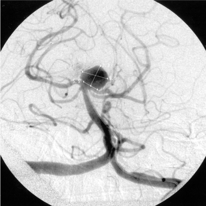
A 60-year-old man presented with an unruptured basilar apex aneurysm measuring 9 mm in diameter with a 5.5 mm neck. Problematic was the fact that the neck incorporated 3 mm of the left posterior cerebral artery (PCA) (figure 1). Attempts were made to coil the lesion with complex three dimensional coils manufactured by Micrus (Sunnyvale, CA), Micro Therapeutics, Inc (Irvine, CA), and Boston Scientific (Fremont, CA). Due to the neck's aperture the coils continually herniated out of the aneurysm and into the parent vessel. Consideration was given to placing a Neuroform stent (Boston Scientific, Fremont, CA) from the basilar artery into one of the PCAs, but despite numerous attempts with a variety of shapeable wires we were unable to advance a microcatheter into the left PCA secondary to the angle at which the vessel arose from the aneurysm and the fact that the left PCA shared a considerable portion of the aneurysm's neck with the fundus1,2. While we were able to access the right PCA, we felt that after stent deployment into this vessel the neck would remain too large to ensure lack of coil herniation into the unprotected, nonstented left PCA. "Y" coiling using the technique described by Chow et Al. was not an option since we could not access the left PCA3. Balloon remodeling using the technique described by Baldi et Al. was considered as it has been used by our group successfully many times before when dealing with unfavorable fundus to neck ratios4,5,6. Lack of a suitable balloon in our inventory, however, precluded remodeling at this time.
Figure 1.
Left Townes view vertebral artery arteriogram showing the basilar apex aneurysm.
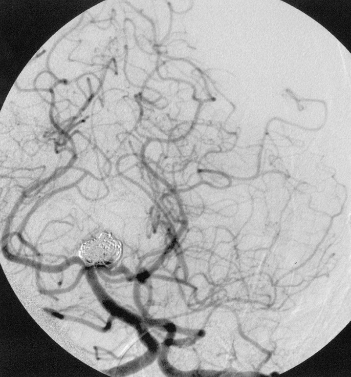
We decided, therefore, to utilize a dual catheter technique in the hope that intoduction of two complex three dimensional coils simultaneously into the aneurysm would cause the coils to interlock with one another and remain within the fundus. After placing a 7F shuttle catheter into the left vertebral artery (Cook Corp., Bloomington, IN) two 3F Rapid Transit Microcatheters (Cordis-Johnson and Johnson, Miami Lakes, FL) were advanced into the aneurysm using the road mapping technique. Through each catheter we then introduced two 7 mm 360 degree GDC coils (Boston Scientific, Fremont, CA) into the aneurysm. Without releasing either coil they were simultaneously manipulated so that together they remained locked in place and secure within the fundus. Once we were sure that the coil mass was stable one coil was released while the other was kept attached to its introducer wire. Additional GDC 360 degree coils and ultrasoft coils were then introduced into the aneurysm while one of the original two 360 degree coils remained secured to its tether. Once the embolization was complete one microcatheter was removed from the patient. The second of the two initially placed 360 degree coils was finally released and the final catheter was removed from the patient. Prior to this coil's detachment, however, gentle pressure was placed on the introducer wire so that the tip of the catheter protruded out of the coil mass and sat slightly within the basilar apex. This was done so that once the final coil was released the catheter would already rest proximal to the coil mass thus not risking moving the mass into the parent vessel during catheter removal. The final result showed complete aneurysm obliteration without coil herniation (figure 2}. The patient was discharged the following day without complications.
Figure 2.
Left Townes view vertebral artery arteriogram following coiling.
Case 2
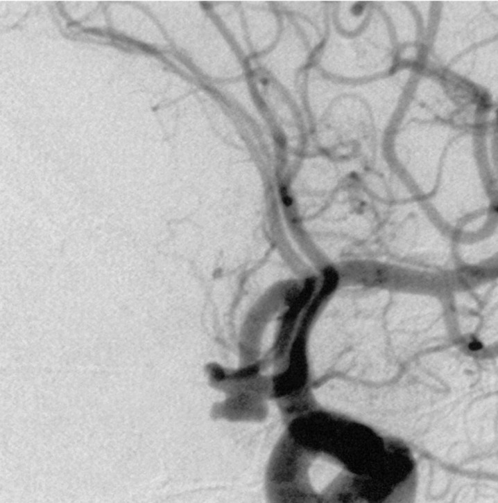
A 73-year-old woman presented Hunt and Hess Grade 1 with a 6 mm × 3.5 mm anterior communicating artery (ACA) aneurysm (figure 3).
Figure 3.
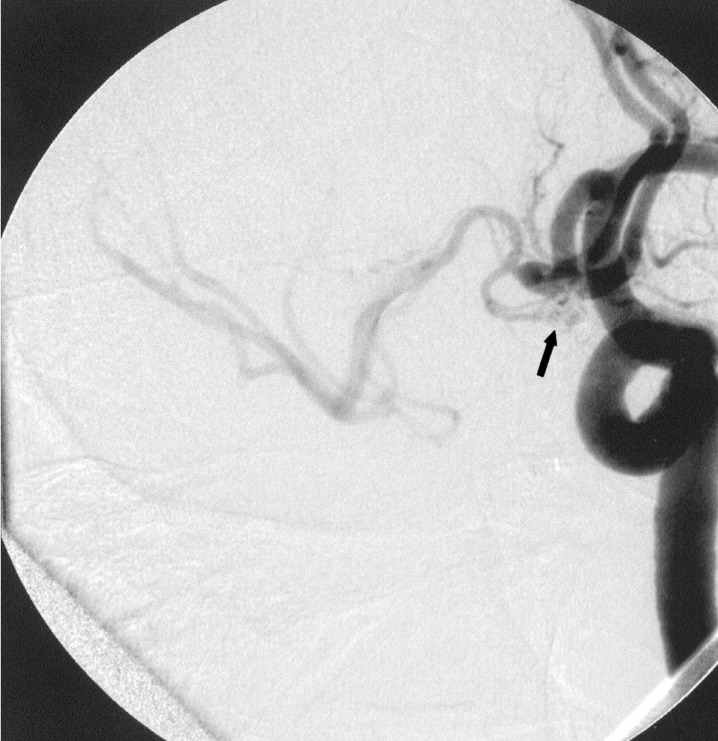
Left oblique internal carotid artery arteriogram showing anterior communicating artery aneurysm.
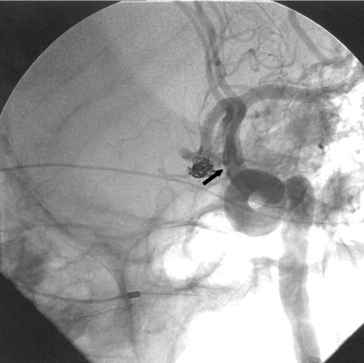
The patient supplied both hemispheres via the left A1 as a right A1 was absent. Following sytemic heparinization (ACT 290) the aneurysm was catheterized using a Rapid Transit microcatheter placed through a 6F Envoy (Cordis Johnson and Johnson, Miami Lakes, FL) guiding catheter positioned in the left internal carotid artery (ICA). Attempts were made to coil the lesion using Micrus and MTI three dimensional complex coils, however the coils repeatedly herniated out of the aneurysm and into the efferent vessels. A second 6F Envoy guiding catheter was then placed in the left common carotid artery and a second Rapid Transit microcatheter was advanced into the aneurysm's fundus (figure 4). Simultaneous deployment of two Micrus spherical framing coils (5 mm and 4 mm diameter) was then carried out throngh each microcatheter. Adjustments of the two coils were made until they interlocked and remained within the aneurysm. The 5 mm coil was then released and additional Micrus spherical framing coils and GDC ultrasoft coils were placed into the aneurysm until it was well filled. One microcatheter was now removed and the second of the two initially placed Micrus framing coils was then released and its catheter was removed (figure 5). As in case 1, the second catheter was positioned just proximal to the aneurysm's aperture by gently advancing its coil's introducer wire prior to coil deployment to ensure that the catheter's tip would rest outside the aneurysm and not cause coil mass dislodgement during final catheter removal. The patient was discharged two weeks later with a normal neurologic examination.
Figure 4.
Left oblique internal carotid artery arteriogram showing anterior communicating artery aneurysm with two catheters within the ACA. The arrow points to the proximal catheter markers with the coil markers just distal to them.
Figure 5.
Left oblique internal carotid artery arteriogram showing anterior communicating artery aneurysm following coiling.
An important aspect of this case was determining which of the two initial Micrus framing coils should be released first after they were each simultaneously introduced and interlocked. We opted to release the coil from the catheter that was positioned more superficially within the aneurysm (the catheter whose tip was closes to the neck) with the thought that it would be safer to introduce additional coils more superficially in the aneurysm as opposed to deeper in the aneurysm. Deeper deposition of coils in this wide necked lesion we felt ran the risk of pushing more superficially place coils out of the aneurysm and into the parent vessel. Nevertheless, by leaving the deeper positioned catheter and coil for the final detachment meant that the catheter would have to be withdrawn through the coil mass thus risking dislodgement of the entire mass during final catheter removal. It was for this reason that we opted to position the final catheter's tip just proximal to the aneurysm's aperture prior to releasing the coil. As a result, once the coil was deployed the catheter was already free of the aneurysm and its potentially unstable coil mass.
Discussion
Procedure
For the reader's benefit a step-by-step description of the procedure as we perform it is listed below.
1. Access right common femoral artery (CFA) and left CFA with a 6F sheath using a micropuncture or single wall puncture system. As an option a single CFA may be accessed using a 7F shuttle catheter so that both microcatheters can be placed through a single lumen.
2. The guide catheters are placed in the appropriate conducting vessel. For anterior circulation lesions the 7F shuttle may be placed into the appropriate ICA, two 6F guide catheters can be placed in a single ICA or one 6F catheter can be positioned in the ICA while the other 6F catheter can be placed into the ipsilateral common carotid arterv. For posterior circulation aneurysms located below the vertebral confluence a single 7F shuttle catheter can be placed in the appropriate vertebral artery (VA). two 6F guiding catheters can be placed in the appropriate VA, or one 6F catheter can be placed in a VA while the second is positioned in the subclavian artery. For posterior circulation aneurysms located above the confluence single VA access can be used or 6F guided catheters can be placed in each VA.
3. The patient is full heparinized with 5000 units of heparin.
4. Road mapping images are obtained to visualize the aneurysm in its best projection.
5. The aneurysm is sequentially catheterized with the microcatheter.
6. Coils are introduced into the aneurysm using either simultaneous insertion through each catheter or sequential insertion through each catheter.
7. The coils are manipulated until they are presumed to be stable within the aneurysm fundus. One coil is released and the other is kept tethered to its introducer.
8. Additional coils are introduced until the surgeon feels the mass is stable. The coil that was left tethered to its introducer wire (see step 7) is now released. One catheter can now be removed from the aneurvsm while additional coils are introduced through the other microcatheter until the aneurysm is fully treated.
9. Once coiling is completed the final microcatheter is removed.
10. Depending upon the patient's need for additional invasive procedures and the appearance of the aneurysm/vessel interface the patient may or may not be given Ilb/IIIa inhibitors.
Wide-necked aneurysms remain difficult to treat endovascularly due to the inherent desire for coils to herniate out of the aneurysm fundus and into the parent vessels. A number of techniques and devices have been developed over the past decade to aid in the treatment of such lesions. These include complex three dimensional coils, liquid agents, stents, neck protection devices, and balloons 1-13. The use of the dual catheter technique, however, remains under-reported despite its effectiveness. While no hard and fast rules exist regarding how to perform this procedure the neurointerventionlist should consider the following issues when using dual catheter coil deposition:
1. Size of the conducting artery
Depending upon the diameter of the conducting artery the surgeon should decide upon the use of a single 7F shuttle catheter or two 6F guide catheters. If two guide catheters are being used, placement of one catheter in the internal carotid artery and the other in the common carotid artery should be considered. When coiling a posterior circulation aneurysm at or above the vertebral confluence it is possible to place one 6F guide catheter into each vertebral artery if a single vertobral artery will not accommodate a 7F sbuttle.
2. ACT
If two catheters are being placed (guide and micro) through the same vessels the surgeon should consider the dose of heparin used and the ACT. We tend to keep the ACT a little higher than usual (approximately 300) so as to reduce the risk of clot formation secondary to increased catheter burden within the vessels. We also recognize that multiple catheter and coil repositionings within the fundus may be necessary to obtain a stable coil mass and that such multiple maneuvers have the likelihood of dislodging thrombus that may form along the coils and catheters.
3. Use of Ilb/IIIa inhibitors
The use of IIb/IIIa inhibitors should be considered even with ruptured aneurysms due to the increased coil face that presents itself to the circulation in situations of wide-necked aneurysms. In ruptured lesions it may be prudent to place a ventriculostomy prophylactically prior to coiling so that this procedure does not need to be performed once platelets are inhibited.
4. Coil choice
Coil choice remains up to the discretion of the surgeon. The goal of the dual catheter technique is to have the first two deposited coils interlock and hold one another within the aneurysm fundus. We have found that the deposition of two complex coils at the start of the procedure has the greatest likelihood of forming a stable mass that resists herniation into the parent vessels during subsequent coil packing. The coils remain attached to their introducer wires until the desired two coil configuration is obtained. If one or both coils herniate into the parent vessel they remain attached to their introducer wire and can be removed from the patient so that inadvertent parent vessel occlusion or stenosis is avoided. The first coil is released at a time when the surgeon feels the mass is stable. The second coil is left attached to its introducer wire so as to provide further mass stabilization. Additional coils are then introduced through the available microcatheter until it is felt that the entire mass is stable. At that point the remaining member of the originally introduced coil pair is detached.
5. Which coil should be released first?
It is often just an educated guess as to which of the two coils should be released first. We tend to consider catheter position within the aneurysm when making this decision. Because we are worried about subsequent movement of the coil mass out of the aneurysm during later coil placement we generally release the more superficial coil first and leave the deeper coil attached until the end of the procedure. The opposite sequence, in our opinion, risks depositing additional coils deeper in the fundus and possibly dislodging the entire mass tow-ards the aneurysm neck and parent vessels. Determination of which coil is most superficial can be problematic at times due to coil overlap. In addition to trying to keep track of the coils as they are introduced into the aneurysm it is often useful to utilize live subtraction road mapping techniques during coil introduction. Once a first coil is placed a live subtraction image can be obtained to subtract out the first coil so that the second introduced coil becomes visible in terms of location, shape and position.
6. Microcatheter removal
Because the aneurysm neck is wide there is always the concern that as the microcatheters are removed from the aneurysm at the end of the case they will also withdraw the coil mass from the fundus and into the parent vessels. We take extreme care at the end of the procedure to advance the remaining non-deployed coils into the aneurysm such that the forward pressure on the delivery wire causes the respective catheter tip to rest at the most proximal portion of the fundus. By doing so we do not have to worry about withdrawing the catheter through the entire coil mass once the final coil is released.
7. Patient follow-up
For wider-necked aneurysm we tend to plan our first follow-up angiographic imaging at three months as opposed to the usual six months. The risk of coil compaction is greater in such lesions and repeat treatment is often necessary.
Conclusions
A variety of neuroendovascular options exist for the treatment of wide necked aneurysms. The majority of the time these techniques, which often involve the use of ancillary or modified devices such as three dimensional complex coils, stents and/or balloons, are efficacious. Nevertheless, cases do arise which are not amenable to such devices. When these situations arise the surgeon must decide to use additional methods or have the aneurysm treated exovascularly. The dual catheter method should be considered as a viable alternative for management of aneurysms with unfavorable fundus to neck ratios.
References
- 1.Benitez RP, Silva MT, et al. Endovascular Occlusion of Wide-Necked Aneurysms with a New Intracranial Microstent (Neuroform) and Detachable Coils. Neurosurgery. 2004;54:1359–1367. doi: 10.1227/01.neu.0000124484.87635.cd. [DOI] [PubMed] [Google Scholar]
- 2.Wanke I, Doerfler A, et al. Treatment of Wide-Necked Intracranial Aneurysms with a Self-Expanding Stent Syndrome: Initial Clinical Experience. Am J Neuroradiol. 2003;24:1192–1199. [PMC free article] [PubMed] [Google Scholar]
- 3.Chow MM, Woo HH, et al. A Novel Endovascular Treatment of a Wide-Necked Basilar Apex Aneurysm by Using a Y-Configuration, Double-Stent Technique. Am J Neuroradiol. 2004;25:509–512. [PMC free article] [PubMed] [Google Scholar]
- 4.Baldi S, Mounayer C, et al. Balloon-Assisted Coil Placement in Wide-Neck Bifurcation Aneurysms by Use of a New, Compliant Balloon Microcatheter. Am J Neuroradiol. 2003;24:1222–1225. [PMC free article] [PubMed] [Google Scholar]
- 5.Nelson PK, Levy D. Balloon-Assisted Coil Embolization of Wide-Necked Aneurysms of the Internal Carotid Artery: Medium-Term Angiographic and Clinical Follow-Up in 22 Patients. Am J Neuroradiol. 2001;22:19–26. [PMC free article] [PubMed] [Google Scholar]
- 6.Horowitz MB, Levy EI. Endovascular Management of Wide-Necked Aneurysms. Contemporary Neurosurgery. 2001;23:1–8. [Google Scholar]
- 7.Klisch J, Schellhammer F, et al. Combined Stent Implantation and Embolization with Liquid 2-Polyhydroxyethyl Methacrylate for Treatment of Experimental Canine Wide-Necked Aneurysms. Neuroradiology. 2002;44:503–512. doi: 10.1007/s00234-001-0761-z. [DOI] [PubMed] [Google Scholar]
- 8.Raymond J, Guibert F, Roy D. Neck-Bridge Device for Endovascular Treatment of Aneurysms: Initial Experince. Radiology. 2001;221:318–326. doi: 10.1148/radiol.2212010474. [DOI] [PubMed] [Google Scholar]
- 9.Raymond J, Salazkin I, et al. Endovascular treatment of Experimental Wide Neck Aneurysms: Comparison of Results Using Coils or Cyanoacrylate with the Assistance of an Aneurysm Neck Bridge Device. Am J Neuroradiol. 2002;23:1710–1716. [PMC free article] [PubMed] [Google Scholar]
- 10.Vallee JN, Pierot L, et al. Endovascular Treatment of Intracranial Wide-Necked Aneurysms Using Three-Dimensional Coils: Predictors of Immediate Anatomic and Clinical Results. Am J Neuroradiol. 2004;25:298–306. [PMC free article] [PubMed] [Google Scholar]
- 11.Horowitz MB, Levy EI, et al. Transluminal Stent-Assisted Coil Embolization of a Vertebral Confluence Aneurysm: Technique Report. Surg Neurol. 2001;55:291–296. doi: 10.1016/s0090-3019(01)00421-9. [DOI] [PubMed] [Google Scholar]
- 12.Vallee JN, Pierot L, et al. Endovascular Treatment of Intracranial Wide-Necked Aneurysms Using Three-Dimensional Coils: Predictors of Immediate Anatomic and Clinical Results. Am J Neuroradiol. 2004;25:298–306. [PMC free article] [PubMed] [Google Scholar]
- 13.Leonardi M, Simonetti L, et al. 3D Micrus Coil "Cage" in Wide-Necked Aneurysms. Interventional Neuroradiology. 2003;9:141–152. doi: 10.1177/159101990300900203. [DOI] [PMC free article] [PubMed] [Google Scholar]


